
Abstract
Study Design:
A narrative literature review.
Objectives:
To review the surgical techniques of posterior screw fixation in the subaxial cervical spine.
Methods:
A broad literature review on the most common screw fixation techniques including lateral mass, pedicle, intralaminar and transfacet screws was performed on PubMed. The techniques and surgical nuances are summarized.
Results:
The following techniques were described in detail and presented with illustrative figures, including (1) lateral mass screw insertion: by Roy-Camille, Louis, Magerl, Anderson, An, Riew techniques and also a modified technique for C7 lateral mass fixation; (2) pedicle screw fixation technique as described by Abumi and also a freehand technique description; (3) intralaminar screw fixation; and finally, (4) transfacet screw fixation, as described by Takayasu, DalCanto, Klekamp, and Miyanji.
Conclusions:
Many different techniques of subaxial screw fixation were described and are available. To know the nuances of each one allows surgeons to choose the best option for each patient, improving the success of the fixation and decrease complications.
Introduction
Internal fixation of the cervical spine is a common procedure performed by spine surgeons in different settings such as trauma, degenerative conditions, infection, neoplasm, and congenital malformations.
Prior to the advent of various screw fixation techniques, cervical spine fixation was limited to either in situ fusion or wiring techniques. The in situ fusion is achieved by using autogenous bone grafts such as harvested iliac crest or ribs, along with postoperative external cervical immobilization. Despite the long periods of postoperative bracing, this technique had a high rate of pseudoarthrosis. 1,2
Subsequently, various wiring techniques were developed in an effort to improve the fusion rate and clinical outcome. 1,2 Many of these techniques are still useful today in selected cases, especially in pediatric patients whose small spinal dimensions often preclude the use of screw fixation. However, wiring techniques did not offer immediate stability and provided poor resistance against extension, side bending, and rotational forces. 3 In addition, the pseudoarthrosis rates remain high despite improvement compared with in situ fusion. 4,5
Modern techniques for posterior subaxial cervical stabilization mainly use a screw-rod construct, which is much stronger biomechanically. This can often translate into higher fusion rates, earlier mobilization and rehabilitation, and ultimately superior clinical outcome. 6 -9 The most commonly used screw fixation techniques of the posterior subaxial cervical spine include lateral mass, pedicle, intralaminar, and transfacet screws. 8 -12
After conducting a thorough literature review, we aim to summarize and present these 4 screw fixation techniques in detail, along with discussions on the relevant surgical anatomy, indications, contraindications, as well as surgical pearls for each of these techniques.
Basic Surgical Anatomy of the Subaxial Cervical Spine
The cervical spine is the most mobile segment in the spinal column. 13 It consists of 7 vertebrae, with the upper 2 vertebrae having unique anatomical characteristics and names: the atlas (C1) and the axis (C2). 14 The subaxial cervical vertebrae (C3 to C7) have similar anatomical characteristics. 10 -12 The spinous processes are generally bifid from C3 to C5, and becomes either bifid (47.9%) or monofid (47.9%) at C6, and usually monofid at C7 (99.2%). 15 The C7 vertebra, also known as the vertebra prominens, is the largest cervical vertebra and its spinous process is easily palpable. 13
The vertebral artery (VA) most commonly enters the transverse foramen at C6, with only a small percentage of patients with variants course entering at C7 or C5 either unilaterally or bilaterally. 13 Therefore, the course for VA should be studied on preoperative magnetic resonance imaging and any vascular anomalies should be noted to prevent inadvertent VA injury. In majority of the cases, the VA passes anterior to the lateral mass of C7, which is important to note during C7 pedicle screw fixation.
There are 8 pairs of cervical spinal nerves, with the C1 nerve roots leaving above the C1 posterior arch between the atlas and the occiput, and the C8 nerve leaving between C7 and T1 pedicles. Thus, the cervical nerves generally course above the corresponding vertebral pedicle, with exception of the C8 nerves that exit between the pedicles of C7 and T1. 13,14,16
The cervical neuroforamen is bound cranial-caudally by the cervical pedicles, anteriomedially by the intervertebral disc and uncinate process, and lateroposteriorly limited by the facet joints. 13,14,16
General Considerations
All the patients should be positioned prone using either a Mayfield head holder with the neck in the neutral position, or a Gardner-Wells tongs with bivector cervical traction depending on the surgeon. 1,17 The posterior cervical spine incision is performed in the midline in the avascular and amuscular plane in the standard fashion. 17 There should be minimal or no bleeding if done meticulously with minimal trauma to the adjacent musculature. Excessive dissection of the levels beyond the operative levels should be avoided to preserve as much posterior tension band as possible, especially at C2 and C7 because of the large and important muscular insertions. A subperiostal exposure with monopolar cautery is performed with adequate visualization of the posterior spinal elements for proper screw insertion.
Lateral Mass Screw Fixation
The lateral mass screw fixation in the cervical spine was first described by Roy-Camille in 1964. 18 Several other techniques have been described subsequently with different entry point and screw trajectories. 6 -9 In the following section, commonly used lateral mass screw insertion techniques are reviewed. In general, angling the screw trajectory laterally helps reduce the risk of vertebral artery injury, whereas angling cranially helps to reduce the risk of facet joint violation (a caudal entry point may increase the chances of facet joint violation if the screw trajectory is not aimed cranial enough). However, a cranially pointed, excessively long lateral mass screw can cause impingement of the exiting nerve root above.
Surgical Techniques of Lateral Mass Screw Insertion
Roy-Camille et al technique (Figure 1)
18
: Entrance point: midpoint of the lateral mass. Lateral angulation: ∼10° from the sagittal plane Sagittal inclination: 90° to the lateral mass surface (perpendicular to the bony surface). Nazarian and Louis technique (Figure 2)
19
: Entrance point: intersection point of a vertical line 5 mm medial to the lateral edge of the facet joint, and a horizontal line 3 mm below the inferior edge of the underlying facet. Lateral angulation: straight ahead, 0° lateral angulation Sagittal inclination: 90° to the lateral mass surface (perpendicular to the bony surface) Magerl technique (Figure 3)
9
: Entrance point: 1 mm medial and 1 mm cranial to the midpoint of the lateral mass. Lateral angulation: about 20° to 30° from the sagittal plane Sagittal inclination: parallel to the adjacent facet joints. Anderson et al technique (a modification of Magerl’s technique) (Figure 4)
8
: Entrance point: 1 mm medial to the center of the lateral mass Lateral angulation: 10° Sagittal inclination: screws directed 30° to 40° in a cephalad direction (also parallel to the facet joints). An et al technique (Figure 5)
6,7
: Entrance point: 1 mm medial to the center of the lateral mass for C3-6 Lateral angulation: 30° laterally from the sagittal plane Sagittal inclination: 15° of cephalad angulation. Riew technique (Figure 6): Entrance point: 1 mm medial and 1 mm caudal to the center of the lateral mass Lateral angulation: aim toward the upper and outer corner of the lateral mass Sagittal inclination: aim toward the upper and outer corner of the lateral mass

Roy-Camille technique of lateral mass screw fixation. (A) Entrance point: midpoint of the lateral mass. (B) Lateral angulation: 10°. (C) Sagittal inclination: Screw inserted at 90° with the cortical surface of the lateral mass (perpendicular).

Nazarian and Louis technique of lateral mass screw fixation. (A) Entrance point: 5 mm medial to the lateral edge of the facet and a horizontal line 3 mm below the inferior edge of the underlying facet. (B) Lateral angulation: 10°. (C) Sagittal inclination: Screw inserted at 90° with the cortical surface of the lateral mass (perpendicular).

Magerl technique of lateral mass screw fixation. (A) Entrance point: slightly medial and cranial to the midpoint of the lateral mass. (B) Lateral angulation: 20° to 30°. (C) Sagittal inclination: Screw inserted parallel to the adjacent facet joints.
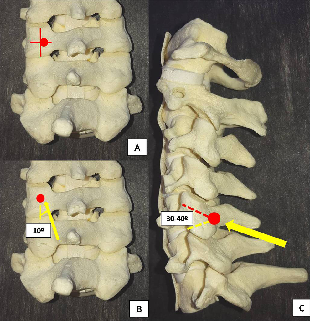
Anderson technique of lateral mass screw fixation. (A) Entrance point: 1 mm medial to the midpoint of the lateral mass. (B) Lateral angulation: 10° (C) Sagittal inclination: Screw inserted at 30° to 40° with the cortical surface in a cephalad direction (parallel to the facet joints).
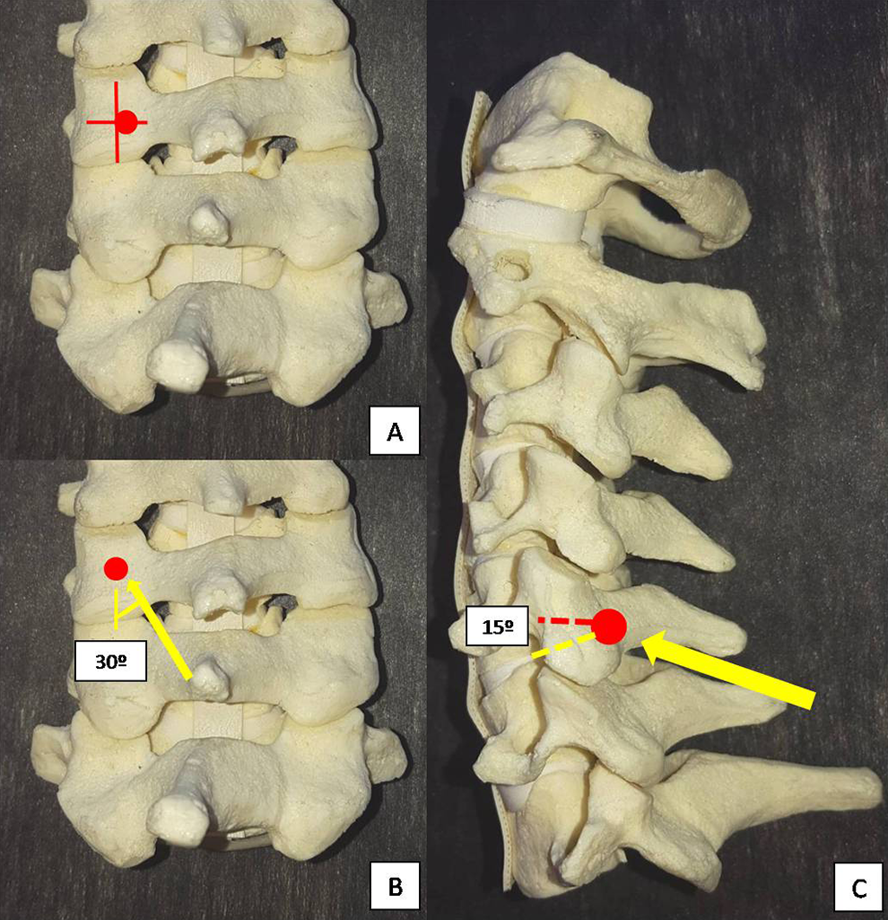
An technique of lateral mass screw fixation. (A) Entrance point: 1 mm medial to the midpoint of the lateral mass. (B) Lateral angulation: 30°. (C) Sagittal inclination: Screw inserted at 15° with the cortical surface in a cephalad angulation.
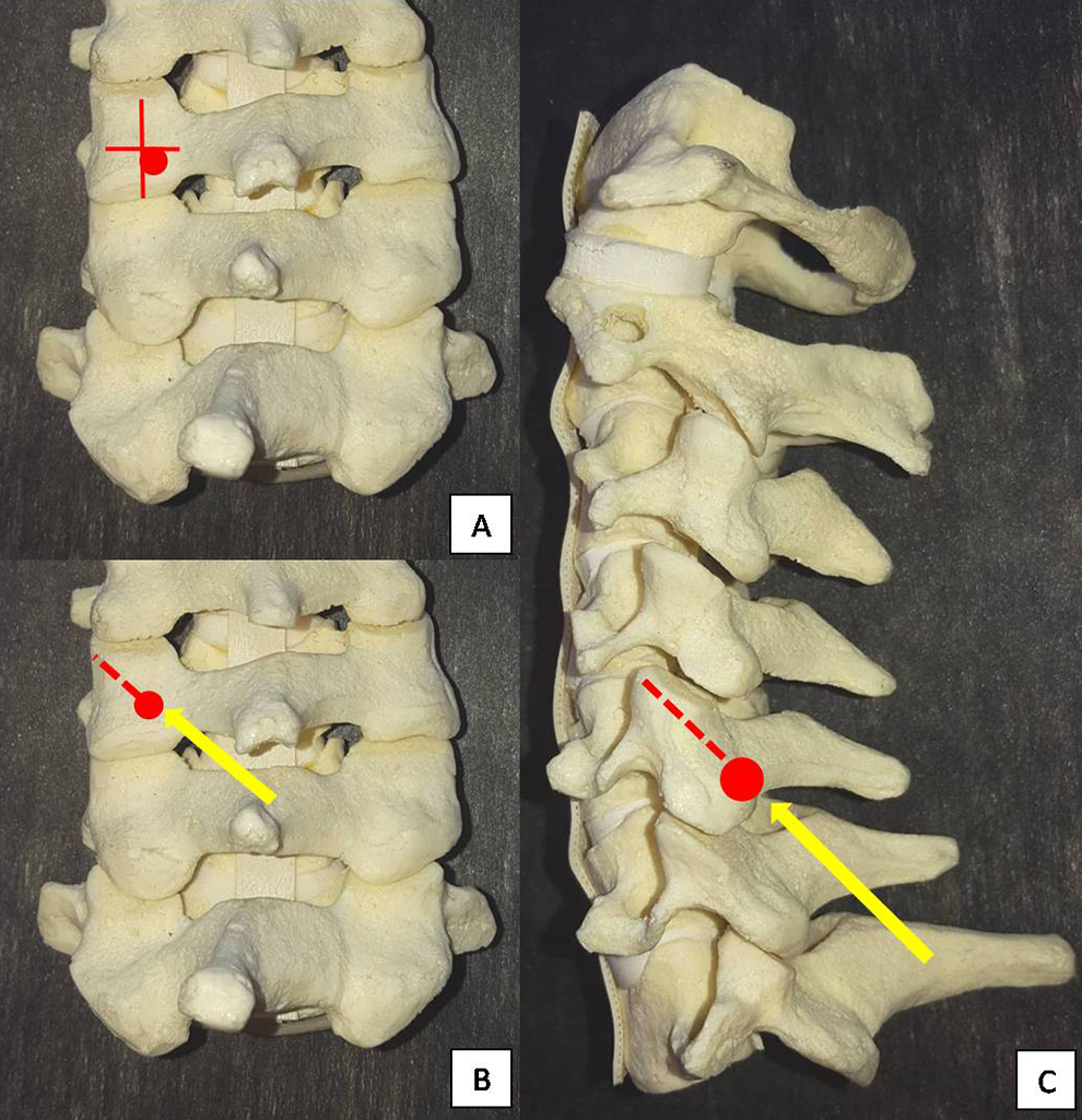
Riew technique of lateral mass screw fixation. (A) Entrance point: 1 mm medial and 1 mm caudal to the midpoint of the lateral mass. (B) Lateral angulation: toward the upper and outer corner of the lateral mass. (C) Sagittal inclination: toward the upper and outer corner of the lateral mass.
Peculiarities of C7 Lateral Mass Screw Fixation
The C7 vertebra is a transitional vertebra at the cervicothoracic junction. It has the largest vertebral body and the longest spinous process in the cervical spine, but with a quite thin lateral mass compared with the other lateral masses from C3 to C6. Additionally, the facet joint between C7 and T1 has a morphology that is more similar to a thoracic facet joint. All the techniques described above are used for C7 lateral mass fixation as well. However, if upper thoracic instrumentation is used, C7 fixation can often be omitted given the strong fixation points provided by the upper thoracic pedicles. If C7 is the lowest instrumented vertebra, then pedicle screw fixation should be considered, especially if the construct expands multiple levels, has no anterior fixation or is in an osteoporotic individual, to avoid instrumentation failure with a small C7 lateral mass screw. If a C7 lateral mass screw is used, care must be taken to ensure that the C7-T1 facet joint is not violated, as it is quite easy to do so if not careful. Intraoperative radiographic confirmation is mandatory and if it is not possible, then postoperative computed tomography (CT) should be considered.
Abdullah et al 20 performed virtual measurements of C7 lateral mass screws using CT. Because of the unique morphologic features at C7, they reported that none of the existing lateral mass screws techniques accounted for C7 vertebra’s unique anatomy. In their study, they compared the Roy-Camille, Magerl, and a modified Magerl technique in 50 patients (25 men and 25 women). Complications were defined as foraminal or facet joints violation (in the coronal, sagittal, or axial plane), or the inability to place a screw longer than 6 mm or achieve good bony purchase. Standard Magerl and Roy-Camille techniques were used, and the modified Roy-Camille consisted in a starting point similar to the Magerl technique (superomedial to the center of the lateral mass), with a lateral angulation of 15° and a sagittal angulation of 90° with the surface of the lateral mass (Figure 7 illustrates this proposed modified trajectory). This technique allowed lateral mass placement in 46 patients, compared with 28 using the Magerl technique and 24 in the Roy-Camille technique. Four patients could not have acceptable C7 lateral mass screw using any method. They concluded that this modified Roy-Camille technique using a higher starting point may be a better option for C7 lateral mass screw fixation, avoiding placing the screw into the T1 facet joint.
Modified Roy-Camille technique for C7 lateral mass screw fixation (Abdullah et al). (A) Entrance point: slightly medial and cranial to the midpoint of the lateral mass. (B) Lateral angulation: 15°. (C) Sagittal inclination: Screw inserted at 90° with the cortical surface of the lateral mass (perpendicular).
Complication Profile
Xu et al 21 performed an anatomic study comparing 3 techniques of lateral mass screws: Magerl, Anderson, and An. For each technique, 1 specimen received 20 screws from C3 to C7 using 20-mm screws to purposefully overpenetrate the lateral masses. The nerve violation obtained was 95% (Magerl technique), 90% (Anderson technique), and 60% (An technique) (P < .05). 21 They concluded that the An technique had a lesser risk of nerve root injury using longer screws. Similarly, in an anatomical study of 26 cadavers, Henler et al 22 performed a comparison of the Roy-Camille and Magerl techniques by inserting about 80 to 100 screws by each of the 3 participating spine surgeons. After inspecting the nerve roots, facet joints, vertebral arteries, and spinal cord by an independent observer, they found that Roy-Camille screws were properly inserted in 89.9% of the early and 93.3% in the late specimens, compared with 41.2% of the early and 80% in the late specimens using Magerl technique. There was only 0.8% of nerve root injury in the Roy-Camille screws compared with 7.3% in the Magerl screws (P = .02). On the other hand, facet joints violation occurs in 22.5% of Roy-Camille versus 2.4% in the Magerl screws (P = .001). Therefore, this study suggested that the Roy-Camille technique has a higher predilection for facet violation, while the Magerl technique has a higher risk for nerve root injury.
Considering screws sizes, Stemper et al 23 performed a CT-based study of 98 young volunteers measuring the bicortical screws lengths using the Roy-Camille and Magerl techniques of lateral mass screw fixation from C3 to C7. For both techniques, the trajectories at C4-6 were greater, with shorter length at C3 and shortest at C7. Men had larger dimensions than women at all levels. The mean Magerl screw length was 2.6 mm longer than Roy-Camille at C3 to C6, and 1.3 mm longer at C7. They reported minimal correlation between screw lengths with height and body weight. A preoperative evaluation of the lateral masses at each level using CT scan is recommended for proper size selection. If pre-operative CT is not available, the screw size can be determined with sequential tapping with a hand drill, and frequently palpation with a ball-tip probe to determine the optimal screw length.
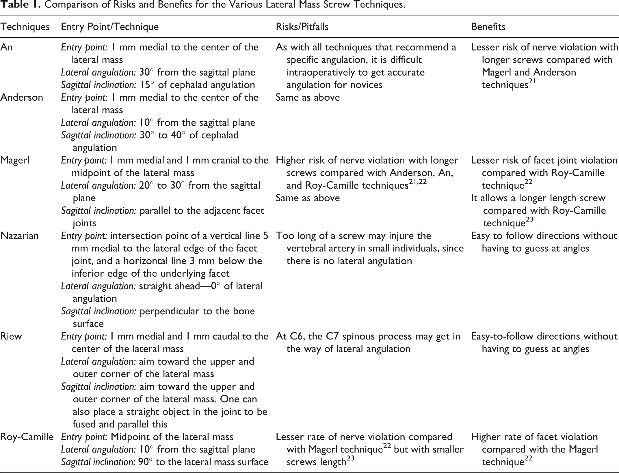
In Table 1, we present a comparison of the risk and benefits for the various lateral mass screw techniques.
Comparison of Risks and Benefits for the Various Lateral Mass Screw Techniques.
Pedicle Screw Fixation
Pedicle screw fixation is widely used and popularized in the thoracolumbar spine. It provides patients early and strong biomechanical support to achieve spinal stabilization and arthrodesis. However, in the subaxial cervical spine, pedicle screw placement is challenging due to the small pedicle size, as well as the close proximity of the vertebral arteries. Thus, this technique is often criticized for having a higher risk of neurovascular injury. 18
Abumi et al 11 popularized the use of pedicle screws of the subaxial cervical spine, which provides circumferential stability with greater pull-out strength compared with lateral mass screws. For C2 and C7 vertebrae, pedicle screws are more commonly used due to wider pedicle diameters. At C7, the absence of the vertebral artery in the transverse foramen in the vast majority of the patients also makes VA injury much less likely. More recently, intraoperative 3-dimensional image–based navigation has helped improve pedicle screw insertion in the cervical spine. However, even with modern intraoperative navigation system, minor and major violations still can occur, which may cause severe and devastating complications. 24
Surgical Technique of Cervical Pedicle Screw Fixation
Abumi et al technique (Figure 8)
11
: Entrance point: slightly lateral to the center of the lateral mass and close to the inferior margin of the inferior facet joint of the cranially adjacent vertebra. Lateral angulation: about 25° to 45° medial to the midline in the transverse plane. Sagittal inclination: parallel to the upper endplate for the C5-6-7 pedicles, and slightly cephalad for the pedicles at C2-3-4.
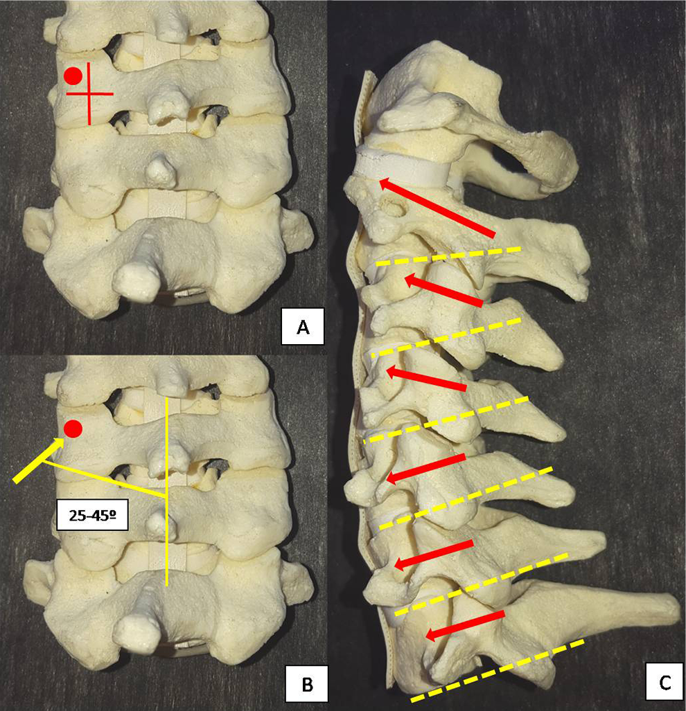
Pedicle screw fixation—Abumi et al technique. (A) Entrance point: slightly lateral to the midpoint of the lateral mass and close to the inferior edge of the inferior facet joint of the cranially adjacent vertebra. (B) Medial angulation: 25° to 45°. (C) Sagittal inclination: Screw inserted parallel to the adjacent facet joints.
Freehand Technique for C7 Pedicle Screw Fixation
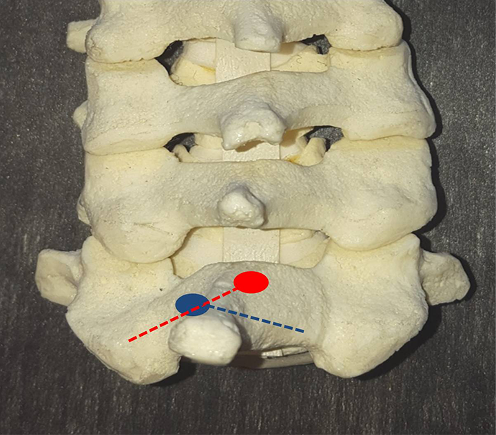
The C6-7 facet joints are carefully exposed. The center of the junction of the lateral masses of C6 and C7 are identified and the entry point is slightly lateral (2-4 mm) to this region, just below the inferior facet joint of C6. The medial angulation is about 45° from the midline, measured before using axial CT scan of the C7. To access the sagittal angulation, the screw is inserted in 90° with the superior facet joint of C7. Screw length may be assessed using preoperative CT. In cases where the pedicle has small dimensions, or a laminectomy is performed, a right-angle probe may be used to palpate the C6-7 and C7-T1 foramen, providing an accurate limit of the C7 pedicle. If the freehand technique fails, one can make a small laminotomy to palpate the medial and cranial walls of the pedicle to guide the insertion.
C7 Intralaminar Screw Fixation
Another option of screw fixation at C7 is translaminar screws. This can be a very helpful bailout technique when C7 fixation is need and the lateral mass/pedicle screw fixation is not possible. The freehand technique for C7 translaminar screw is described as following
25,26
: A small initial hole is made about 4 mm at the caudal aspect of the spinolaminar junction, whereas the second hole is made in the rostral aspect of the spinolaminar junction on the other side. A hand drill is then used aimed the opposite lamina with slightly increments, checking violation of the cortical with a ball trip probe. Screws of about 3.5 × 24 mm are then inserted.
25
Figure 9 illustrates the surgical technique.
Laminar screw fixation technique. Entrance point: One hole is made about 4 mm at the caudal aspect of the spinolaminar junction, whereas the second hole is made in the rostral aspect of the spinolaminar junction and the trajectory. A hand drill is then inserted and slowly progressive toward the contra lateral lamina and the trajectory is checked with a ball trip probe.
Ilgenfritz et al 12 performed a radiographical and biomechanical study to evaluate the use of C7 laminar screws. Seventy-two patients had a CT scan to measure the thickness, length and spinolaminar angle of the lamina. 12 Additionally, 13 cadaveric specimens were obtained and received C2 bilateral intralaminar screws, C7 bilateral intralaminar screws and bilateral C7 pedicular screws (3.5 mm diameter and 20 mm long were considered universally accepted in all specimens). Each specimen was cyclically loaded for 5000 cycles with axial screws pullout tests performed. The mean laminar thickness and length of C7 was 5.67 ± 1 mm (range from 7.5 to 18 mm) and 25.49 ± 2.73 mm (range from 18.5 to 32.2 mm), respectively. The mean spinolaminar angle was 51.26° ± 3.57°. There was no statistical difference between the pullout strength between C7 translaminar and C7 pedicle screws (P = .06).
Transfacet Screw Fixation
Transfacet screw fixation in the cervical spine was first described by Roy-Camille et al in 1972 in the setting of lateral mass fractures. 27 Even though not as widely used as lateral mass screws, several biomechanical studies have shown that transfacet screws have similar mechanical stability and superior screw pull-out strength compared with lateral mass screws. 27,28 Klekamp et al 10 compared biomechanically the pull-out strength of lateral mass screws and screws placed across the facet joints in 10 fresh human cadaveric cervical spines. They reported that cervical transfacet screws (539 N) had a comparable (if not greater than) pull-out resistance to cervical lateral mass screws (379 N) after biomechanical analysis (P = .042). Transfacet screw can be used as either a primary fixation technique or a valuable bailout technique when lateral mass screw and lateral mass screws are not possible.
Takayasu et al 28 reported the clinical results of 81 screws inserted in the middle and lower cervical spine of 25 patients with age from 15 to 84 years. They reported that screw placement, according to their technique described below, was successful and uncomplicated in all cases, without screw backout or loosening during a follow-up ranging from 3 months to 5 years, with fusion achieved in all cases. The techniques described below reported by DalCanto et al, 29 Klekamp et al, 10 and Miyanji et al 27 were detailed in biomechanical studies.
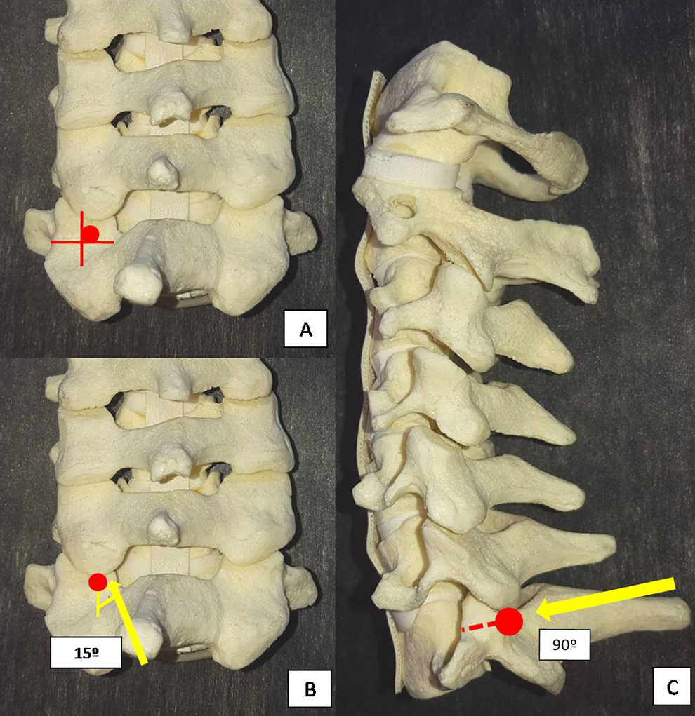
Takayasu technique (Figure 10)
28
: Entrance point: a point on the vertical line bisecting the lateral mass, at the midway caudal third of the lateral mass. Lateral angulation: straight, 0° laterally. Sagittal inclination: 60° to 80° caudally. DalCanto technique (Figure 11)
29
: Entrance point: 2 mm caudal to the midpoint of the lateral mass. Lateral angulation: 20° laterally. Sagittal inclination: 40° caudally. Klekamp technique (Figure 12)
10
: Entrance point: 1 mm medial and 1 to 2 mm caudal to the midpoint of the lateral mass. Lateral angulation: 20° laterally. Sagittal inclination: 40° caudally. Miyanji technique (Figure 13)
27
: Entrance point: midpoint of the lateral mass. Lateral angulation: neutral to 5° laterally. Sagittal inclination: perpendicular to the joint in the cephalocaudal direction.
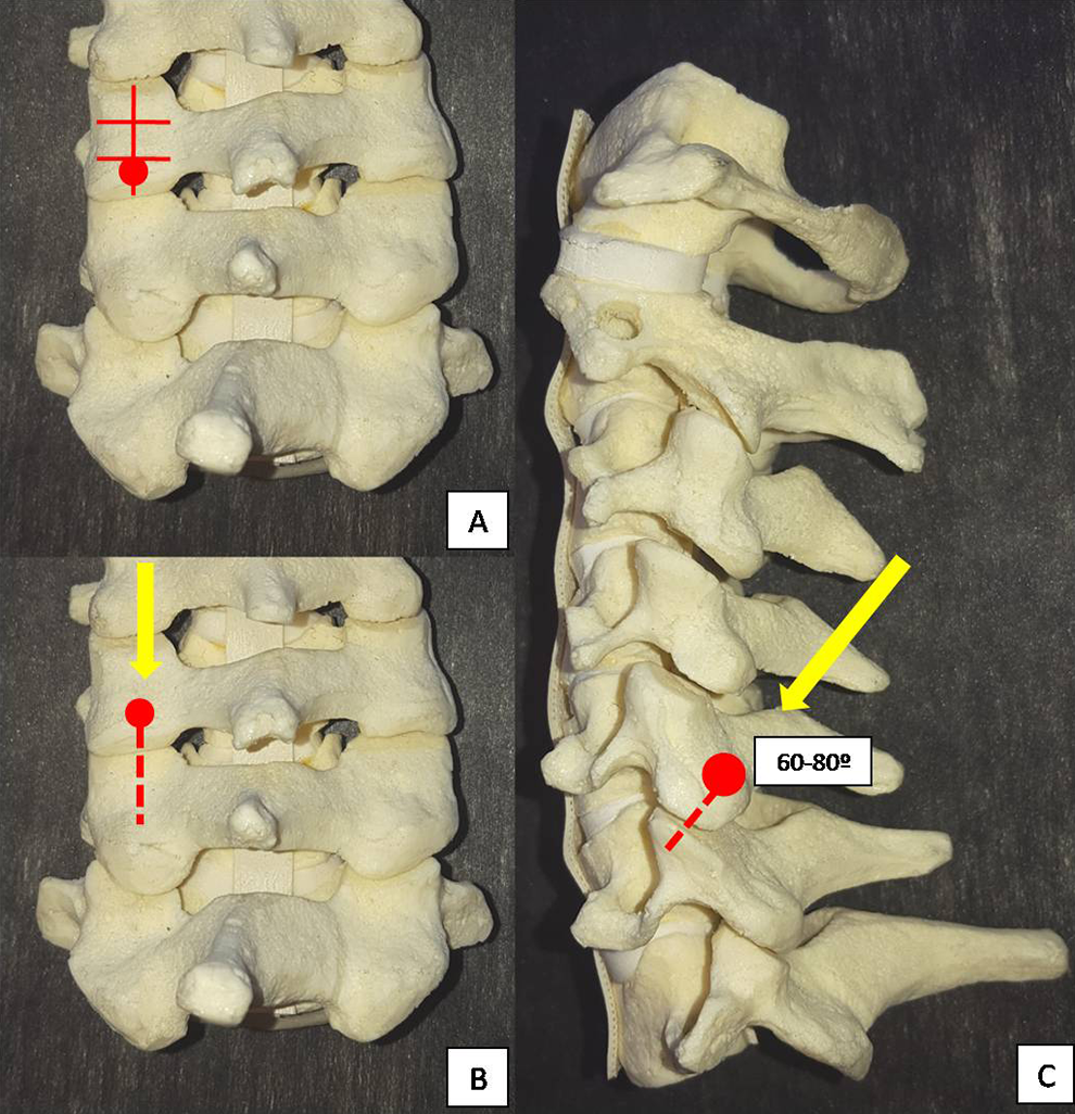
Takayasu technique for transfacet screw fixation. (A) Entrance point: a point in the vertical line bisecting the lateral mass and at the midway caudal third of the lateral mass. (B) Lateral angulation 0°. (C) Sagittal inclination: 60° to 80° caudally on the coronal plane.

DalCanto technique for transfacet screw fixation. (A) Entrance point: 2 mm caudal to the midpoint of the lateral mass. (B) Lateral angulation: 20° laterally. (C) Sagittal inclination: 40° caudally on the coronal plane.
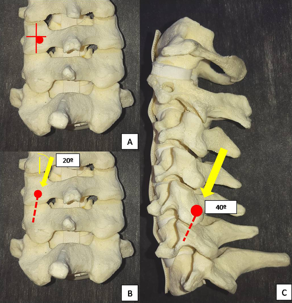
Klekamp technique for transfacet screw fixation. (A) Entrance point: 1 mm medial and 1 to 2 mm caudal to the midpoint of the lateral mass. (B) Lateral angulation: 20° laterally. (C) Sagittal inclination: 40° caudally.

Miyanji technique for transfacet screw fixation. (A) Entrance point: midpoint of the lateral mass. (B) Lateral angulation: 0° to 5° laterally. (C) Sagittal inclination: perpendicular to the joint in the cephalocaudal direction.
Computer-Assisted Surgeries and Cervical Screw Insertion
Currently, computer-assisted surgeries have affected the methods of conventional screw insertion, especially in high-risk patients such as those with anatomical malformations. Intraoperative 3-dimensional CT-based navigation system allows navigation with higher accuracy and lesser violations compared with preoperative CT-based navigation system. 30 Although CA surgeries are useful for all cervical screw techniques, they can be preferentially used for pedicle screws, since they may be biomechanically better than the other techniques but have a higher risk of vascular and neural injury. 30
Abumi et al 31 reported that 45 (6.7%) of a total 669 pedicular screws were misplaced in his early series, but rates of up to 29% of malposition screws were reported by other authors. 32 CA allows a lower rate of screws violation, which may be important especially for less experienced surgeons or in more complex cases. 30
These techniques may certainly improve safety and efficacy of screws insertion when properly used, but they did not preclude a meticulous surgical technique and may increase costs and operative time. 24,30
Conclusions
Many different techniques of subaxial screw fixation were described and are available. To know the nuances of each technique allows the spine surgeon to choose the best option for each patient, improving the success of the fixation and decrease complications.
Footnotes
Declaration of Conflicting Interests
The author(s) declared no potential conflicts of interest with respect to the research, authorship, and/or publication of this article.
Funding
The author(s) received no financial support for the research, authorship, and/or publication of this article.