
Abstract
Study design
Experimental Study.
Objectives
Intraoperative three-dimensional (3D) imaging has been shown to increase patient safety by assuring proper implant placement and often makes postoperative CT imaging obsolete. Nonetheless, there is no data about effective radiation doses in comparison to CT imaging.
Methods
Effective doses of 3D and CT scans were measured with an anthropomorphic phantom (CIRS Inc, ATOM® Dosimetry Phantoms, Norfolk, VA, USA). Clinical presets of the C-arms were used and measured separately (mobile: Cios Spin; fixed: ARTIS pheno; both Siemens Healthcare GmbH, Erlangen, Germany). For CT imaging, a protocol for high-contrast imaging was used (SOMATOM X.cite, Siemens Healthcare GmbH, Erlangen, Germany).
Results
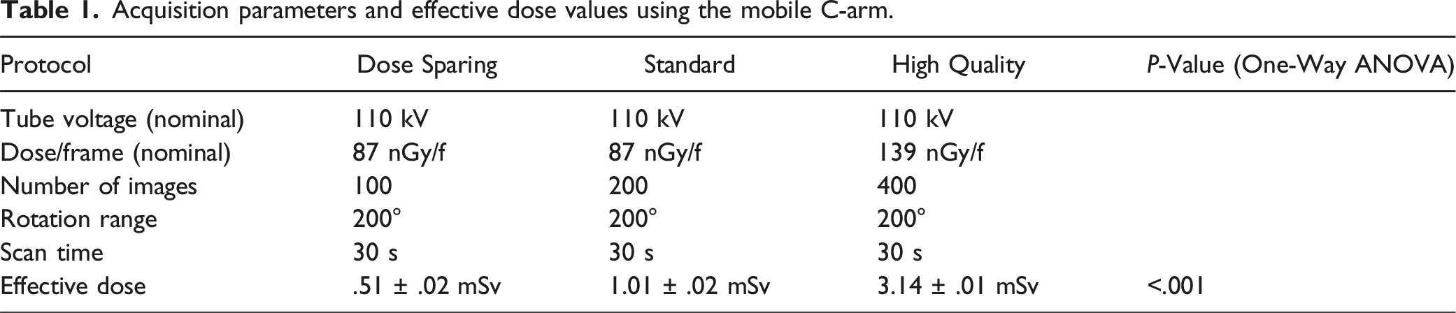
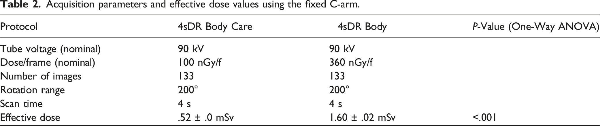
Depending on presets, effective doses with the mobile C-arm ranged from .51 ± .02 mSv (dose-sparing preset) to 3.14 ± .01 mSv (high-quality preset, P < .001). With the fixed C-arm, the effective dose ranged from .52 ± .0 mSv (dose-sparing preset) to 1.6 ± .02 mSv (standard-quality preset, P < .001). With CT imaging, the effective dose was 2.0 mSv.
Conclusions
When evaluating the lumbar spine, the effective dose from intraoperative 3D imaging using mobile and fixed C-arms is comparable to that from CT scans.
Proper choice of intraoperative protocol is essential, as there can be up to a 6-fold variation in dose between protocols. Intraoperative 3D imaging with (mobile or fixed) C-arms has been proven to avoid revision surgery. In this study, effective doses were shown to be comparable to those of CT scans. To avoid unnecessary exposure, indications need to be clear, and the choice of acquiring settings must respect the ALARA principle (“as low as reasonably achievable”).
Introduction
In spine surgery, effective intraoperative monitoring of the procedure is essential to achieve an optimal clinical outcome. Intraoperative three-dimensional (3D) imaging using either mobile or fixed C-arms has been available for around 20 years and has proven to be a reliable and helpful tool for effectively assessing implant positioning.1-4 Recently, the image quality from these cone-beam computed tomography (CBCT) devices has improved so significantly that implant positioning can be fully assessed intraoperatively, and postoperative computed tomography (CT) imaging seems no longer mandatory. 5
Over the past 2 decades, surgical navigation systems have reached a high level of technical sophistication and are increasingly being utilized in spinal surgery.6-8 In many cases, navigation is also based on an intraoperative 3D scan, meaning that patients usually undergo at least 2 3D scans during a navigated procedure. Since intraoperative 3D imaging is available, there is a discussion about the effective radiation exposure to the patient. 9 While changing procedures to 3D workflows, and especially to navigated workflows, reduces exposure for staff because they leave the control area of the device, it was unclear how exposure for the patient developed. 10
Regarding radiation exposure, comparing cone-beam 3D procedures to fluoroscopic (2D) procedures is possible, as CBCT C-arms use a stack of 2D images to create the 3D volume. Depending on the device, these stacks consist of between 50 and 800 2D images which are then reconstructed to produce a 3D volume. These images are dose-optimized, so the resulting exposure is not several hundred times as high as a single 2D image. In fan-beam CT imaging, radiation is released continuously. The information that is received by the detector is called a sinogram and does not contain human-interpretable information. The 3D volume is reconstructed from this sinogram and multiplanar reconstruction planes can be set.
The dose parameters of all fluoroscopy-based devices (2D and CBCT) are dose area product (DAP, μGy * m2) and air kerma (mGy). 1 In fan-beam CT, the parameters are the CT dose index (CTDI, mGy) and dose length product (DLP, mGy * cm). Although these parameters seem similar, they cannot be converted into each other. Due to the different geometry of a fan beam in CT imaging and the cone-shaped radiation field in fluoroscopy, the parameters differ substantially, making it impossible to compare doses on the basis of the radiation parameters.
In this study, the effective dose was measured in an anthropomorphic phantom that allows radiation doses from different imaging systems to be compared. The objective of this study was to compare the effective patient dose from 3D imaging using mobile and fixed C-arm systems to that from a CT scanner.
Methods
To enable the acquisition of realistic data, all measurements were performed using a sophisticated anthropomorphic phantom that made it possible to measure the different geometries of the radiation field. To optimally represent clinical situations, standard imaging modalities and typical routine operating-room settings were chosen.
Phantom
An anthropomorphic ATOM® phantom 701-C (CIRS Inc, Norfolk, VA, USA) was used to measure the effective dose (phantom and setup are shown in Figure 1). The phantom consists of tissue-equivalent epoxy resins. It represents the body of a male human with a height of 173 cm and a body weight of 73 kg. It is made up of 39 slices of 2.5 cm thickness. Each slice has holes measuring .5 cm in diameter arranged in a 1.5 cm × 1.5 cm grid pattern. These are for the dosimeters used to measure the radiation exposure. The phantom complies with the specifications described by the International Commission on Radiological Protection and by the International Commission on Radiation Units and Measurement. 11
Dosimeters
To assess the organ dose, TN 1002RD-H metal oxide semiconductor field effect transistors (MOSFETs) were plugged into the mobileMOSFET system, model TN-RD-70-W (Best Medical Canada Ltd, Ottawa, ON, Canada). The mobileMOSFET system consists of remote monitoring dose verification software, a wireless transceiver, and a reader module that connects the MOSFETs and the software. Up to 5 MOSFETs can be connected to 1 reader. In this study, eight readers and 40 MOSFETs were used for simultaneous measurements.
Prior to the measurements, each MOSFET detector was calibrated. This involved irradiating the MOSFET with a defined radiation dose. The dose level was measured with an ionization chamber (PM500-CII 52.8210, Capintec Inc, Ramsey, NJ, USA) connected to an Unidos dosimeter (PTW, Freiburg, Germany). The ionization chamber was calibrated by PTW according to the national standards of the German National Laboratory, PTB (Physikalisch-Technische Bundesanstalt), Braunschweig, Germany. The mobileMOSFET software automatically calculates the calibration factor as the ratio of the measured voltage to the actual radiation dose for each MOSFET. The anthropomorphic ATOM® phantom used for effective dose measurement: phantom on ground (left) and phantom in experimental setup for 3D acquisition, equipped with MOSFET dosimeters (right).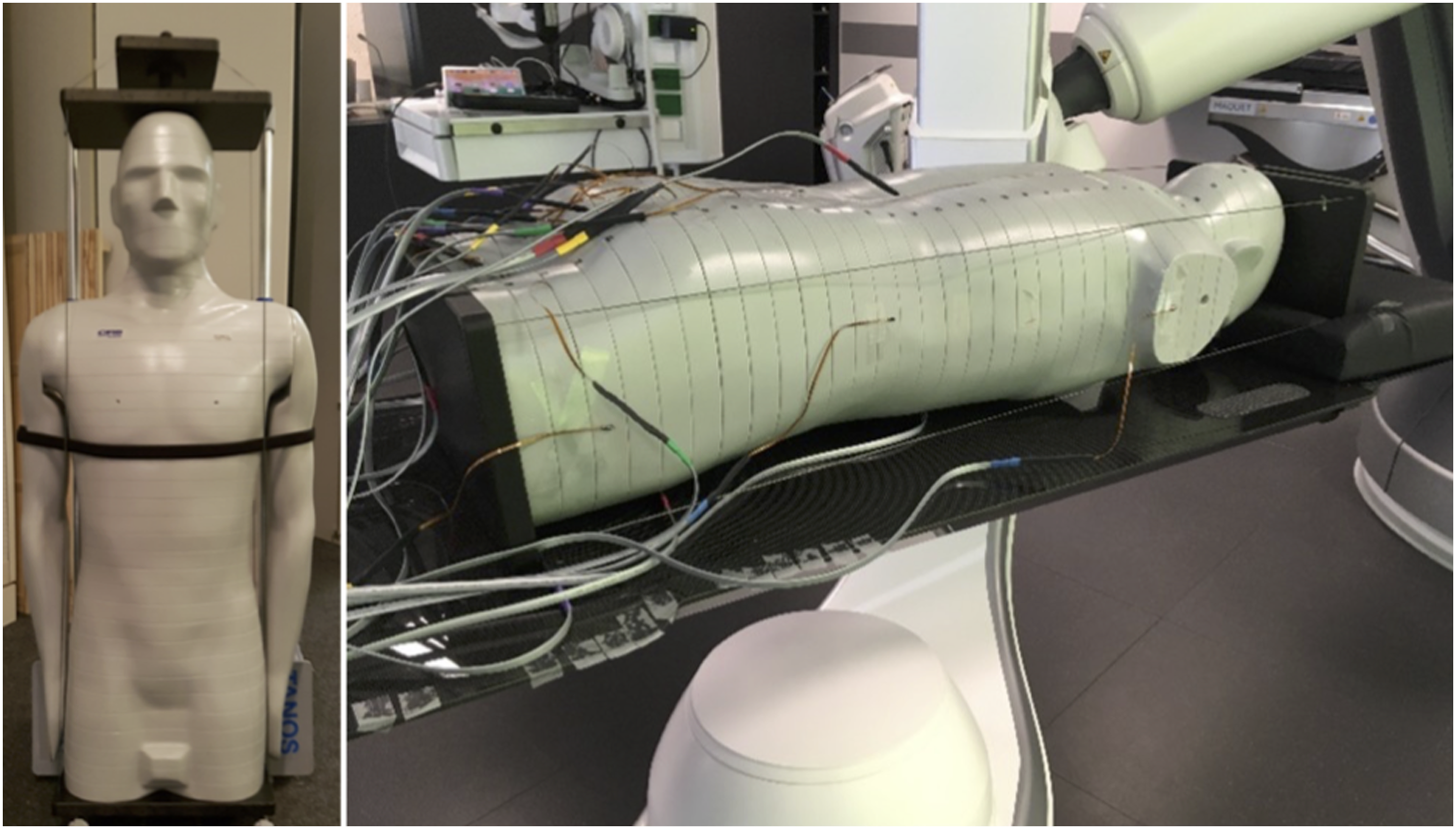
3D Imaging Modalities
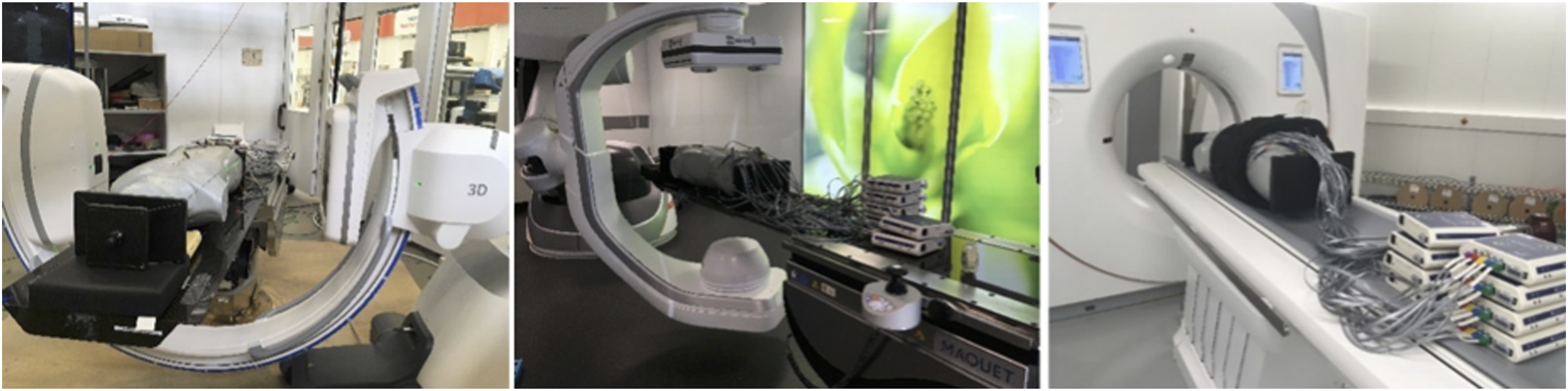
The measurements were performed on 3 different imaging systems, all manufactured by Siemens Healthcare GmbH, Erlangen, Germany (see Figure 2): - Cios Spin mobile 3D C-arm system with Maquet carbon OR table with mattress. The C-arm was positioned right-side with zero-degree table rotation. No collimation was applied. For all protocols, the reconstructed volume size was cubic with an edge length of 16 cm. - ARTIS pheno robotic 3D C-arm angiography system with Maquet carbon OR table with mattress. C-arm was positioned right-side with zero-degree table rotation. Collimation to 16 cm was applied. For all protocols, the reconstructed volume size was a cylinder 24 cm in diameter and 16 cm in height. - SOMATOM X.cite CT scanner with 200 cm patient table and standard mattress. The scan range was collimated to 16 cm in z-direction to match the maximum z-coverage of Cios Spin. Different 3D imaging modalities: the Cios Spin mobile 3D C-arm system (left), the ARTIS pheno fixed robotic 3D C-arm system (middle), and the SOMATOM X. cite CT scanner (right); all systems from Siemens Healthcare GmbH, Erlangen, Germany.
For all systems and investigated 3D imaging protocols, the field of view was positioned in the spine region of phantom (L3 to L5, see Figure 3). The position of the investigated spine area (L3 to L5) of the ATOM® phantom on ARTIS pheno: frontal view (left) and lateral view (right).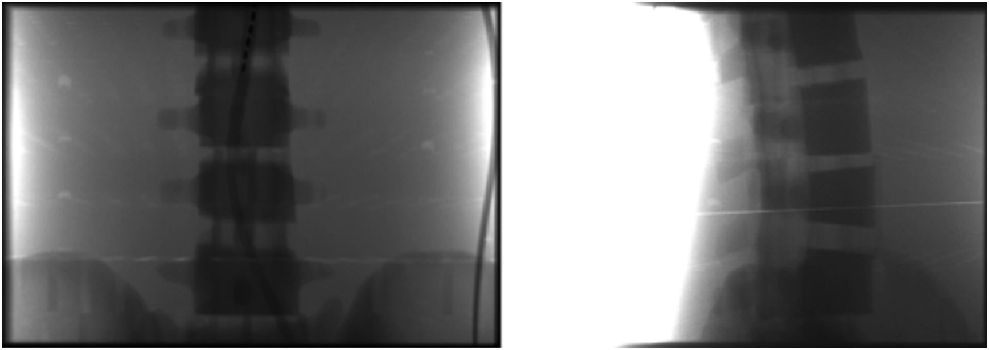
Protocols
Acquisition parameters and effective dose values using the mobile C-arm.
Acquisition parameters and effective dose values using the fixed C-arm.
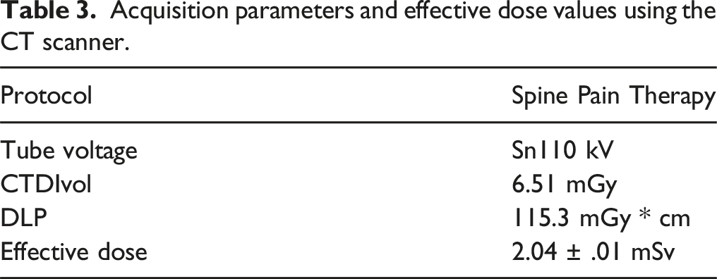
Acquisition parameters and effective dose values using the CT scanner.
Estimation of Effective Dose
The MOSFET dosimeters were placed in 91 measurement locations within the ATOM® phantom. These measurement locations were defined based on the organ map provided by the phantom manufacturer. They represent the anatomical position of organs (such as the brain, thyroid, lung, bone surface, esophagus, liver, stomach, pancreas, adrenal gland, small intestine, spleen, kidney, red bone marrow, bladder, and gonads). To fit the MOSFET dosimeters into the phantom holes, each MOSFET detector was placed in a tissue-equivalent holder.
To measure the skin dose, twelve MOSFET defectors were placed on the surface of the phantom at slices 15, 27, and 37 (see Figure 4). MOSFET detectors positioned on the surface of the ATOM® phantom to measure the skin dose.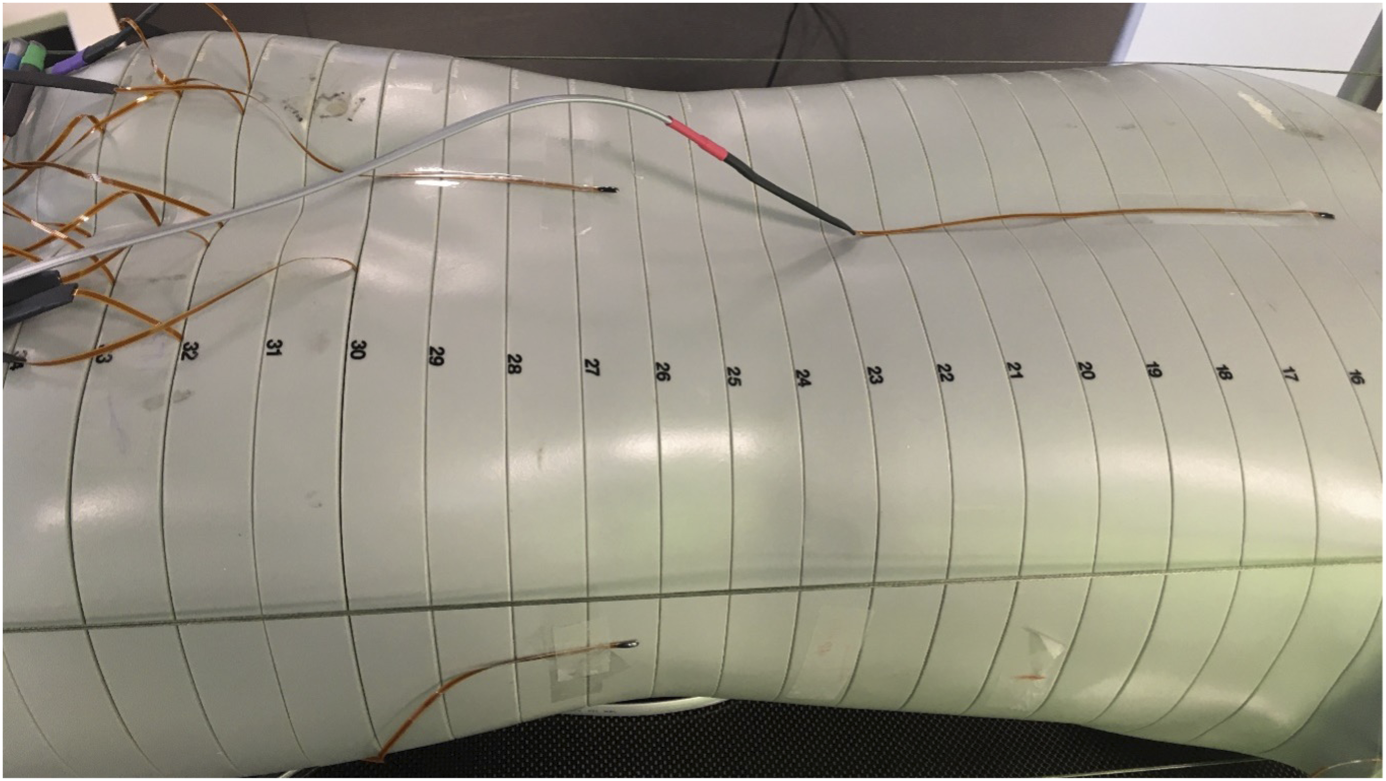
The 3D imaging protocols were performed 3 times to reach the sufficient exposure level for the MOSFET detectors. Then the MOSFET detectors were read out. To measure all locations within and on the surface of the ATOM® phantom, the phantom was re-equipped with the dosimeters twice. The phantom was then positioned in the same field of view. All measurements were repeated 3 times and the mean value of the MOSFET detector readings was used to calculate the organ dose. The organ dose was the mean value of the measured data for all MOSFET detectors placed in the respective organ sites. For organs such as skin, red bone marrow, stomach, liver, pancreas, kidney, intestine, and spleen that were irradiated by both direct and scattered radiation, the fraction of directly irradiated organ volume was considered for calculation of the organ dose. This data was used to calculate the effective dose according to the guidelines of the International Commission on Radiological Protection in Publication 103. 12 The radiation-weighting factor for X-ray was assumed to be 1. The calculated effective dose values for different 3D imaging protocols and systems are summarized in Tables 1–3.
The uncertainty of the MOSFET-dosimeters is below 3% at 20 cGy according to the manufacturer. Extrapolating this data, the uncertainty is below 11% at 20 μGy. The overall accuracy of MOSFET measurements for calculation of effective dose are estimated to be approximately 20%, based on uncertainty for the reference dosimeter (ionization chamber), uncertainty for estimation of the calibration factor for MOSFET detectors, and the uncertainty for calculation of dose for each organ location. 13
Results
The results of the measurements are shown in Tables 1–3. Effective dose ranged from .51 mSv to 3.1 mSv, depending on the setup and protocol.
Discussion
Intraoperative imaging is essential for evaluating implant position and anatomic alignment in spine surgery, especially in posterior minimally invasive pedicle screw placement. Intraoperative 3D imaging enables immediate evaluation of implant placement, the reduction of fractured vertebra, and decompression of osseous spinal canal stenosis. If implant malpositioning is detected, intraoperative revision can be performed promptly. In non-3D workflows, implants are usually evaluated by postoperative CT imaging. 14 This means that a separate operation including anesthesia will be needed to revise malpositioning – entailing a high effort for the surgical team and for the patient.
The availability of new-generation imaging devices capable of intraoperative 3D imaging has substantially improved imaging evaluation inside the OR. 15 With the help of 3D imaging, implant misplacement can be detected and immediately revised. 16 In navigated workflows, precision in implant positioning can even be increased so much that malplacement becomes very unlikely.17-19
In clinical routine, of course other parameters of specific machines than the effective dose play an important role as well. While mobile devices are very versatile and can be used in different rooms, fixed solutions usually offer a larger field of view as well as shorter acquisition times (see Tables 1 and 2). C-arms, no matter if mobile or fixed, offer the option of (2D-) fluoroscopy making a one-stop solution for as well 2D as 3D procedures while intra-operative CT scanners can usually acquire very large volumes with highest image quality. 20
Radiation exposure during surgical procedures is a relevant topic, as increased exposure to ionizing radiation can have severe consequences for both patients and staff.21,22 Depending on actual intraoperative workflows, new imaging solutions can reduce radiation exposure to staff and patients, especially in navigated workflows.23,24
This study has several limitations: The ATOM® phantom is constructed to represent the physiological parameters of a standard male patient. Therefore, the actual doses to which patients are exposed might vary from those measured in the ATOM® phantom. In particular, these measurements will underestimate the dose to slimmer or younger patients. Nevertheless, using an anthropomorphic phantom for effective dose measurements made it possible to compare different imaging modalities and different imaging protocols.
Another limitation concerns the point dose measurements (PMD) used to estimate the organ dose: When measuring inhomogeneous dose distribution by PMD, the technique might underestimate the organ dose. 25 This is because the predefined, fixed locations of the detectors inside and on the surface of the phantom might not represent the real dose distribution within organs or tissues. Another limiting factor that might lead to the overestimation of the organ dose is the fact that the organs might be irradiated by both direct and scattered radiation. This study therefore corrected the organ dose for directly and indirectly irradiated organs by considering the fraction of directly irradiated organ volume.
This study was designed to compare effective dose by different imaging modalities. To transfer the results of the measurements to real-life situations, image quality has to be considered, as well as the presence of implants. Due to the design of the study with the use of the ATOM® phantom, positioning and evaluation of implants was not possible. As shown in several publications, presence of metal implants causes artifacts in imaging that comprise assessability and image quality FIKUART 2025. 26 Further image improvement and artifact reduction algorithms in combination with dose modification might be necessary to enable image evaluation. As this is significantly depending on the actual case as well as type and positioning of implants, integration of image quality and implants was not considered in the current study to allow for maximal standardization. When putting the results into clinical context, this has to be considered.
Conclusion
Two main conclusions can be drawn from this study. First, the data show that the effective dose from intraoperative 3D imaging is in the same order of magnitude that of CT imaging. This does not include questions of image quality, which was not assessed in this study.
Second, while several automated techniques to optimize radiation efficiency and reduce dose have been available for a long period of time and widely used in CT scanners,27,28 users of CBCT-based intraoperative 3D imaging must choose the most appropriate preset based on various patient factors (especially body mass) to avoid unnecessarily high exposition. Depending on the chosen protocol, doses do vary significantly regardless of the actual properties of the patient.
Footnotes
Author Contributions
HS wrote the manuscript, AG, UL, ES and MB organized and performed the measurements and collected data, MP assisted in conceptualizing the study and creating the manuscript.
Declaration of Conflicting Interests
The author(s) declared the following potential conflicts of interest with respect to the research, authorship, and/or publication of this article: AG, UL, ES and MB are employees of Siemens Healthineers AG. Imaging devices used in this study were provided by Siemens Healthineers AG.
Funding
Imaging devices were provided by Siemens Healthineers AG. No specific funding was received for this study.
Ethical Statement
Data Availability Statement
Data is available on reasonable request.