
Abstract
Study Design
Biomechanical Cadaveric Study.
Objectives
Following the successful use of a novel implantable sensor (Monitor) in evaluating the progression of fracture healing in long bones and posterolateral fusion of the spine based on implant load monitoring, the aim of this study was to investigate its potential to assess healing of transosseous fractures of a lumbar vertebra stabilized with a pedicle-screw-rod construct.
Methods
Six human cadaveric spines were instrumented with pedicle screws and rods spanning L3 vertebra. The spine was loaded in Flexion-Extension (FE), Lateral-Bending (LB) and Axial-Rotation (AR) with an intact L3 vertebra and after its transosseous disruption, creating an AO B1 type fracture. The implant load was measured on the one rod using the Monitor and on the contralateral rod by strain gauges to validate the Monitor’s measurements. In parallel, the range of motion (ROM) was assessed.
Results
ROM increased significantly in all directions in the fractured model (P ≤ 0.049). The Monitor measured a significant increase in implant load in FE (P = 0.002) and LB (P = 0.045), however, not in AR. The strain gauge – aligned with the rod axis and glued onto its posterior side – detected an increased implant load not only in FE (P = 0.001) and LB (P = 0.016) but also in AR (P = 0.047).
Conclusion
After a complete transosseous disruption of L3 vertebra, the implant load on the rods was considerably higher vs the state with an intact vertebral body. Innovative implantable sensors could monitor those changes, allowing assessment of the healing progression based on quantifiable data.
Introduction
Traumatic injuries of the spine leading to instability either due to severe burst fractures of the vertebral body (AO type A4), distraction injuries (AO type B), dislocations (AO type C) or neurological impairment, require surgical treatment. 1 Transosseous flexion-distraction (AO type B1) injuries account for 16% of traumatic spine injuries and may include burst fractures in up to half of the clinical cases. 2 Without an injury of the endplates or the intervertebral discs (IVD), fusion surgery aiming at arthrodesis across 1-2 motion segments is not required. Most commonly the injured vertebra is temporarily stabilized using a pedicle-screw-rod construct, which partially shifts the spinal loads from the spine to the stabilizing instrumentation.3,4 The latter can be removed after confirmed healing but there is no consensus on the optimal timing, with recommendations ranging from 6 months to 2.8 years after surgery. 5 However, timely hardware removal can enhance spinal functionality, preserve mobility, prevent future deformities in adjacent segments, and overall improve patient satisfaction regarding quality of life.4-8 In addition, complications such as pseudoarthrosis, with an incidence of up to 5%, 9 and early implant failure, ranging from 2.1% to 3.7%, 10 have been reported following surgical treatment of traumatic spinal fractures. It is therefore imperative to maintain constant awareness of the healing process status in order to react promptly to any disturbances that may arise and, moreover, to enable the implant removal at the earliest opportunity, thus facilitating early mobilization. The assessment of healing progression currently relies on subjective evaluation of patient reported outcome measures, or imaging techniques, such as plain radiographs or computed tomography (CT) scans at a few specific time points after surgery. Even though imaging of the spine is a standard procedure, correct and unambiguous radiological assessment remains a difficult task, especially in real-time detection of complications and abnormal healing processes. 11 Furthermore, it exposes the patient to radiation, particularly critical for young patients, which is the main patient group suffering flexion-distraction injuries. 5 A recent study has reported that standard follow-up visits in the USA were rarely completed. 12 Only 23.7% of them met the recommended one-year follow-up duration, which poses a further risk to correct healing assessment and appropriate patient aftercare.
To address those challenges, timely, radiation-free and quantifiable data is needed. Recent research has increasingly focused on assessing stress and strain differences during tissue growth and repair within the musculoskeletal system. Those studies aimed to enhance the understanding of load-bearing and load-sharing characteristics between implants and tissue, while also enabling in vivo data collection, offering valuable insights for postoperative patient care.13,14 One of those developments has been the AO Fracture Monitor, designed to be attachable to conventional orthopaedic plates to assess their deformation continuously and autonomously throughout fracture healing. This monitoring becomes crucial as implant loading is expected to transfer gradually from the implant to the new forming bone in the course of uneventful healing progression.4,15 By monitoring implant loading, the healing progress can be assessed postoperatively without subjecting the patient to radiation or requiring regular practice or hospital visits. This approach has shown promising results not only in assessing fracture healing of long bones16,17 but also monitoring posterolateral spinal fusion in sheep.18,19
The aim of this study was to investigate the potential of the above-described implantable sensor system (Monitor) in the detection of load changes on a posterior instrumentation after transosseous flexion-distraction spine injuries with additional anterior column damage. Furthermore, strain gauges were used to verify the measurements of the Monitor as well as to find its optimal position and arrangement with respect to the three main loading directions of the spine. For this purpose, a short segment stabilization of L3 vertebra was conducted spanning two functional spinal units (FSU, L2–L3 and L3–L4). Subsequently, the range of motion (ROM) and implant load were assessed in two different stability states: intact vertebra and after a three-column injury initiated by an osteotomy through the spinous process, lamina, and center of the vertebral body of L3 (creating an AO type B1 fracture – Chance fracture).
Materials and Methods
Specimen Preparation
Six fresh-frozen (-20°C) lumbar spines (L1 to S1) were harvested from human cadavers (age: 76 ± 8 years; 4 males and 2 females; trabecular bone mineral density of vertebra L3: 94.1 ± 36.1 mgHA/cm3). Extraneous soft tissues were dissected without harming ligamentous structures, joint capsules, and IVD. The cranial and caudal vertebra were embedded in cylindrical polymethylmethacrylate forms (SCS-Beracryl, Suter Kunststoffe AG, Fraubrunnen, Switzerland) allowing installation of the spine in a customized test setup. Care was taken to align the cranial embedding parallel to the caudal endplate of L3. Vertebra L3 was stabilized using a short-segment posterior instrumentation. For this purpose, pedicle screws (EXPEDIUM VERSE Spinal System, DePuy Synthes, Raynham, MA, USA) were bilaterally inserted under fluoroscopic control into L2 and L4 vertebra and connected by straight titanium rods (5.5 mm diameter).
The right rod was equipped with three strain gauges (SG, Figure 1). The SGs were directly glued on the rod using Z70 adhesive (Hottinger Brüel & Kjaer GmbH, Darmstadt, Germany). One SG (WA-06-030WR-120, Micro-Measurements, Raleigh, NC, USA) was aligned axially with the rod axis. When fixing the rod to the pedicle screw, the rod was rotated around its own axis to position the first SG on the posterior side (posterior SG). The second SG (EA-05-062DF-120, Micro Measurements) was also aligned axially with the rod, however, glued onto the lateral side of the rod (lateral SG). The wire grid of the third SG (WA-06-030WR-120, Micro-Measurements) was aligned at a 45° angle of the rod’s axis on its posterior side (oblique SG) to primarily pick up torsion of the rod. Sensor arrangement on the posterior instrumentation. The Monitor was attached to the left rod by means of titanium clamps and stainless-steel screws. Three strain gauges (SG) were glued to the right rod with their wire grids aligned differently to predominantly pick up surface strain on the rod in flexion extension (Posterior SG), Lateral Bending (lateral SG), and axial rotation (Oblique SG).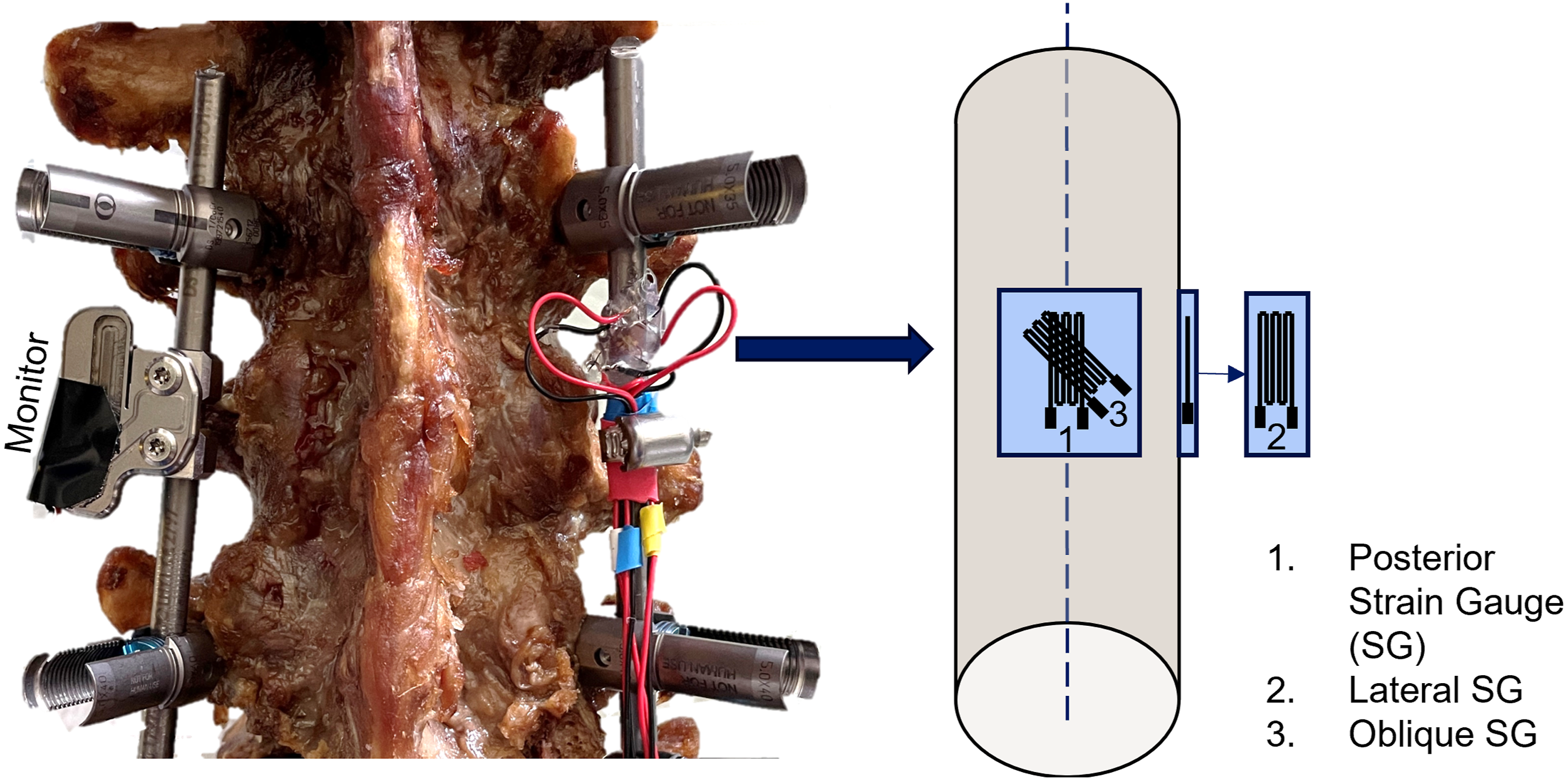
A new implantable load sensing device (AO Fracture Monitor) was attached to the left rod by means of two titanium clamps (Figure 1). This measurement technology is based on SGs, enclosed in the Monitor’s hermetically sealed housing together with a battery and an electronic unit allowing on-board data acquisition and processing, and wireless data transmission through Bluetooth Low Energy. The SGs in the Monitor are positioned between the screw holes and therefore by default aligned with the rod’s longitudinal axis. By rotating the clamps, i.e. the Monitor around the rod, the upper surface of the Monitor was aligned parallel to the frontal plane, hence, the Monitor’s SGs were located posterior to the rod.
Transosseous destabilization of L3 vertebra was conducted using an oscillating saw. After testing the instrumented intact spine (instrumented), the spinous process, lamina, and the vertebral body of L3 were discontinued centrally between the endplates including all bone and ligamentous structures (fractured), simulating severe anterior and posterior column damage. The endplates and IVD were left intact.
Biomechanical Testing
Biomechanical testing was performed on a biaxial servo-hydraulic material testing machine (MTS 858 Mini Bionix II, MTS Systems, Eden Prairie, MN, USA) equipped with a 5 kN/50 Nm load cell (MCS10CV/MPZ2211038, Hottinger Brüel & Kjaer GmbH) and according to a recommendation for in vitro stability testing of spinal implants.
20
An established customized test setup18,19,21 was used to load the specimens unconstraint in the three main anatomical loading directions (Figure 2). The caudal end of the spine was firmly fixed to the baseplate, whereas load was applied to the cranial end of the specimens. The spine was repositioned three times to rearrange the rotation of the test machine transducer and set it up for Flexion-Extension (FE), Lateral Bending (LB), and Axial Rotation (AR) loading of the spine. Other loads were passively compensated by an XY-table, a cardan joint, and actively by the test machine controller holding the vertical load at 0 N during testing. Three bidirectional non-destructive rotational ramps up to ±7.5 Nm were run for each loading direction at a rate of 2°/sec. Test setup for range of motion testing in flexion-extension, lateral bending, and axial rotation comprising load cell (1), XY-table (2), cardan joint (3), cranial fixture (4), optical markers in vertebra L2, L3, and L4 (5), and caudal fixture (6). Load is induced via rotation of the machine transducer (red arrow).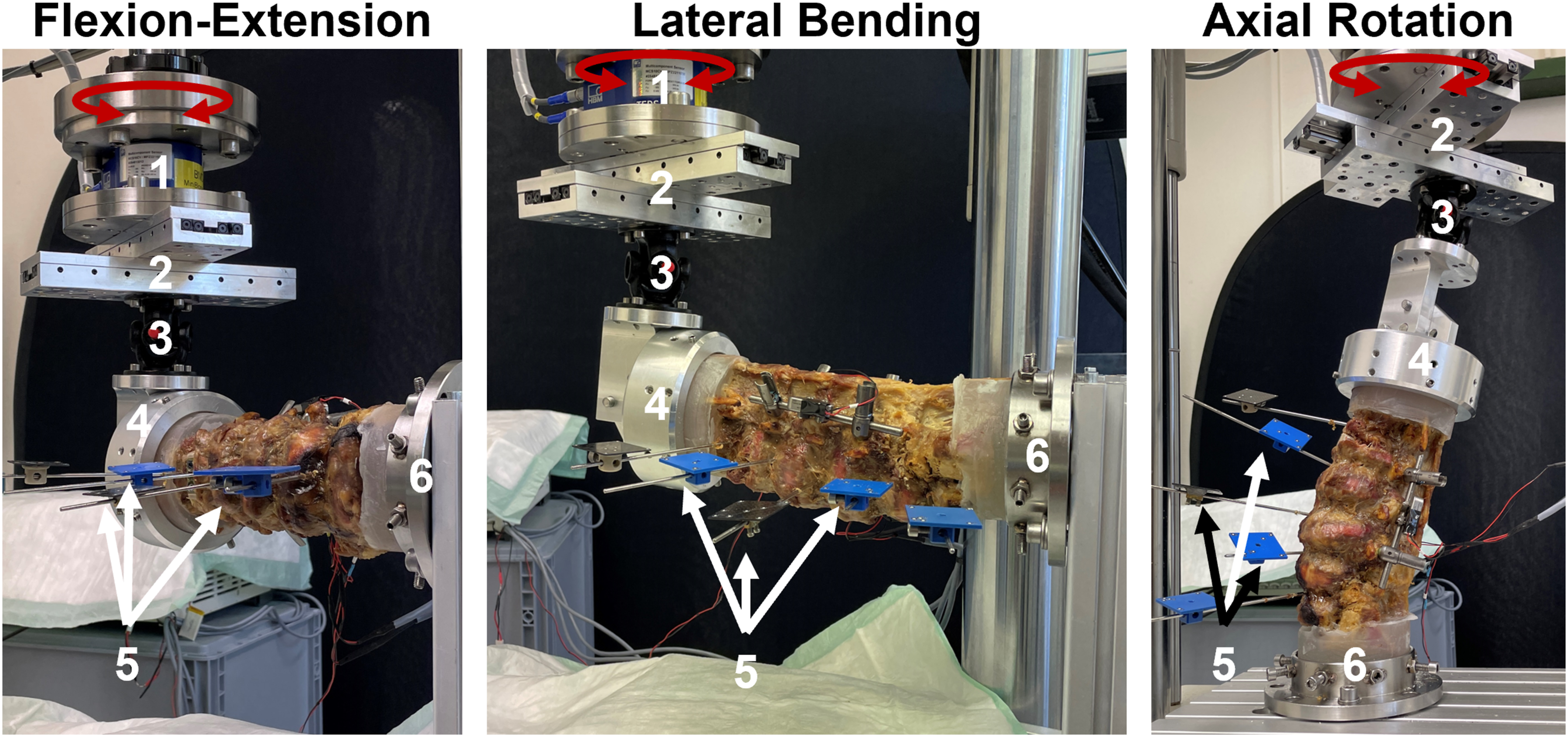
After fixing the specimen in the test setup, vertebra L2, L3, and L4 were equipped with an optical marker set each. The marker set of L3 was placed inferior to the fracture line and defined the reference coordinate system.
Data Acquisition
Rotary and vertical displacement, as well as load and torque were continuously acquired by the test machine controller at 64 Hz. In parallel, the optical markers were tracked at 40 Hz by a stereometric optical measurement system (GOM Aramis SRX, Carl Zeiss GOM Metrology GmbH, Braunschweig, Germany) to allow motion tracking of the FSU in all six degrees of freedom. The reference coordinate system was aligned with the anatomical axes of the caudal endplate of vertebra L3.
Each SG was completed to a quarter Wheatstone bridge (quarter-bridge) using an amplifier (MGCplus AB22A, Hottinger Brüel & Kjaer GmbH), connected to the test machine for data acquisition.
A customized firmware was uploaded to the Monitor to allow for continuous data streaming of the measured load. The Monitor data were displayed in number of binary units (least significant bit, LSB).
Data Evaluation
The peak-to-peak amplitude of the recorded signals during the last full loading cycle were chosen for evaluation. For ROM analysis, the motions of the two spanned FSUs (L2–L3 and L3–L4) were combined. To facilitate a better comparison between the different measures, the data are presented in percentage normalized to the intact state. Therefore, the data from positive and negative loading direction were combined. Each data set was checked on normality of distribution (Shapiro-Wilk test) and subsequently a Paired-Samples t-test was run to check on significant changes between the different states using SPSS (IBM SPSS Statistics 27.0.1, IBM, Armonk, NY, USA). The level of significance was set to P = 0.05 for all statistical tests.
Results
Implant load and ROM were successfully measured for six specimens. ROM increased significantly in all motion directions after complete transosseous disruption of L3 (P ≤ 0.049, Figures 3 and 4). The average gain and its standard deviation were highest in AR. The amplitude in AR and LB was found to be equivalent across both positive and negative load directions. Sum of the range of motion (mean ± standard deviation) of the two spanned segments (L2-L3 and L3-L4) in flexion-extension, lateral bending, and axial rotation. Significant differences are indicated by asterisks (*: P < 0.05 **: P < 0.01). Range of motion (ROM), monitor live stream data (Monitor), and strain data (SG) were normalized to their values measured in the instrumented intact state (100%). Mean ± standard deviation of the different measures for flexion-extension (solid bars), lateral bending (dashed bars), and axial rotation (checkered bars) are displayed. Significant differences between the fractured group and the instrumented group are indicated with asterisks (*: P < 0.05,**: P < 0.01).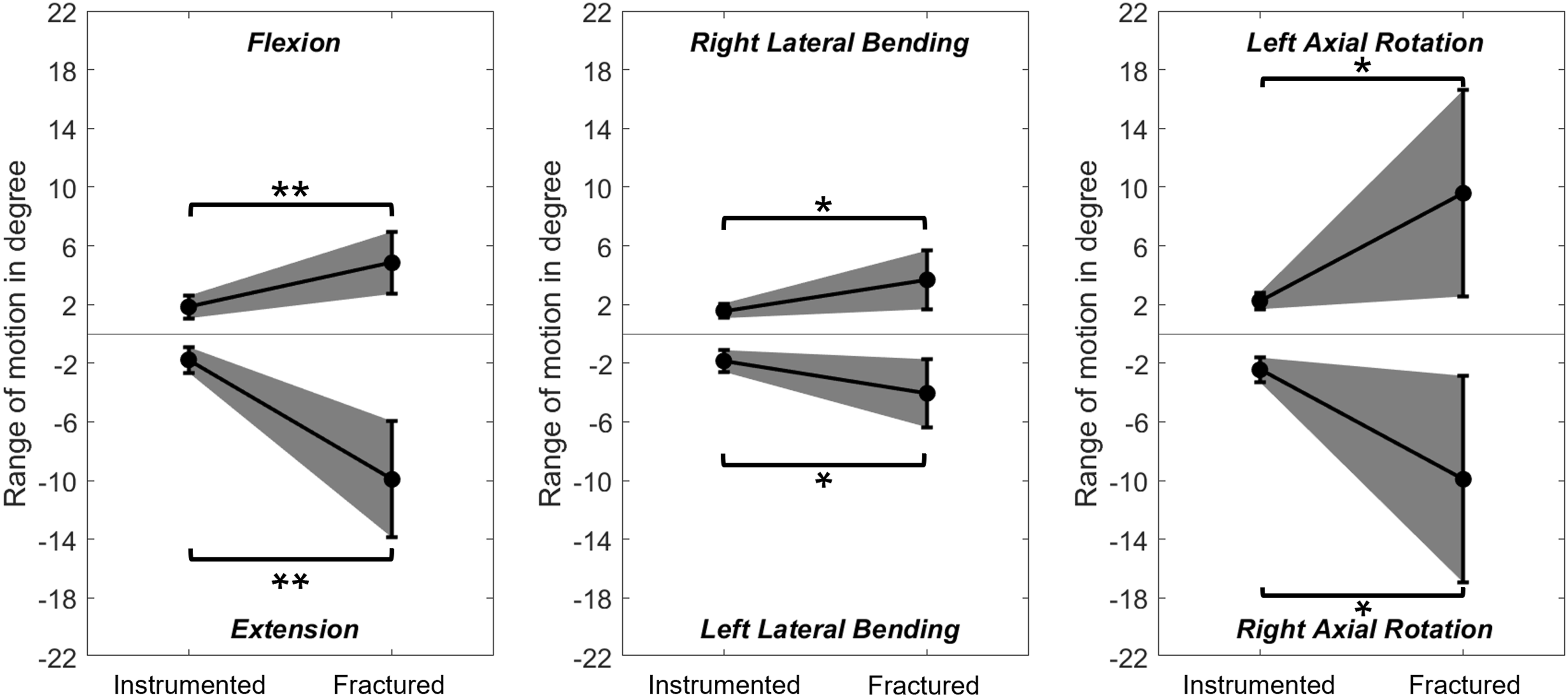
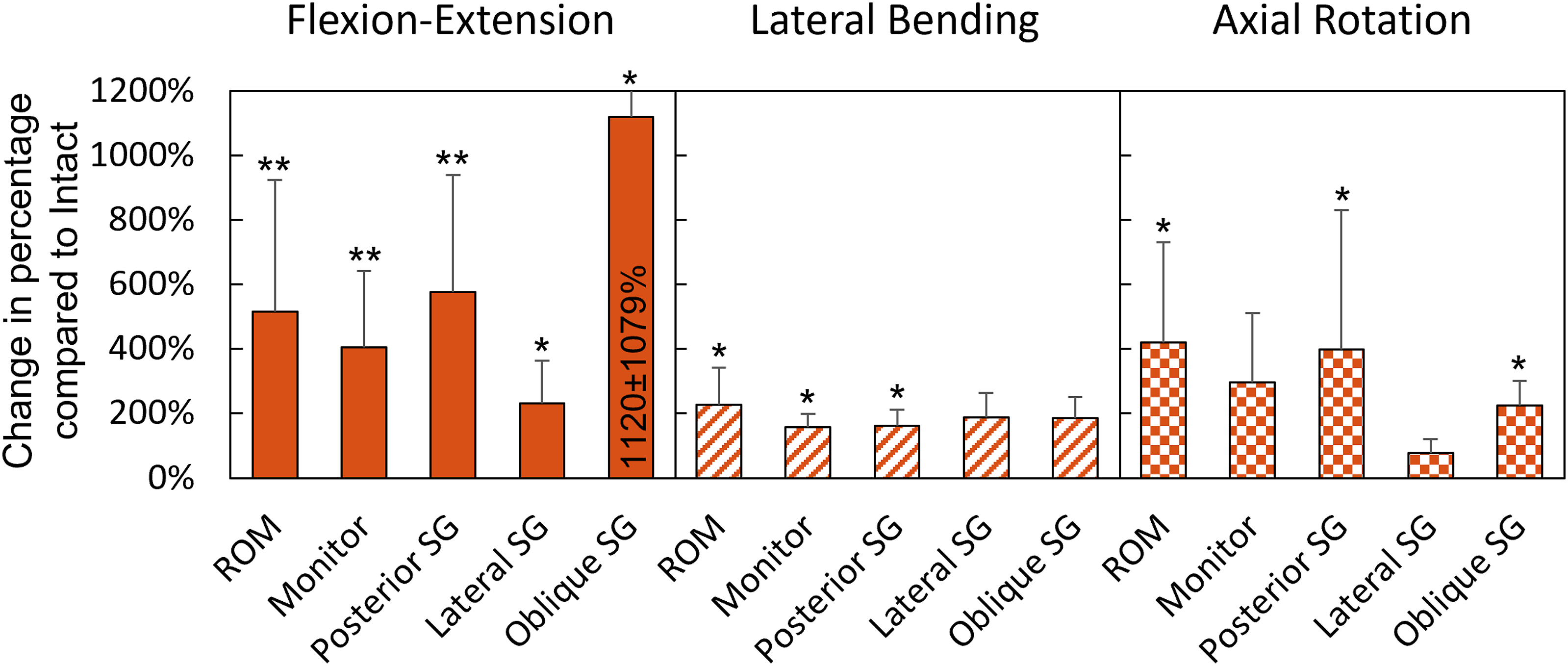
Due to complications during one measurement with the oblique SG, one specimen had to be excluded from statistical analysis of the oblique SG output. A significant increase in strain after fracture creation was detected in FE by the Monitor (P = 0.002), the posterior SG (P = 0.001), the lateral SG (P = 0.020), and the oblique SG (P = 0.046, Figure 4). The majority of the strain difference after creating the fracture was detected in extension motion (Figure 5). In LB, a significant difference between the states was detected only by the Monitor (P = 0.045) and the posterior SG (P = 0.016), however, these relative changes were smaller compared to those measured during FE (Figure 4). In AR, a significant increase in load after disruption of L3 was measured only by the posterior SG (P = 0.047) and the oblique SG (P = 0.022). Exemplary implant loading curves measured by the Monitor and the different strain gauges (posterior, lateral, and oblique SG) in flexion-extension, lateral bending and axial rotation motion.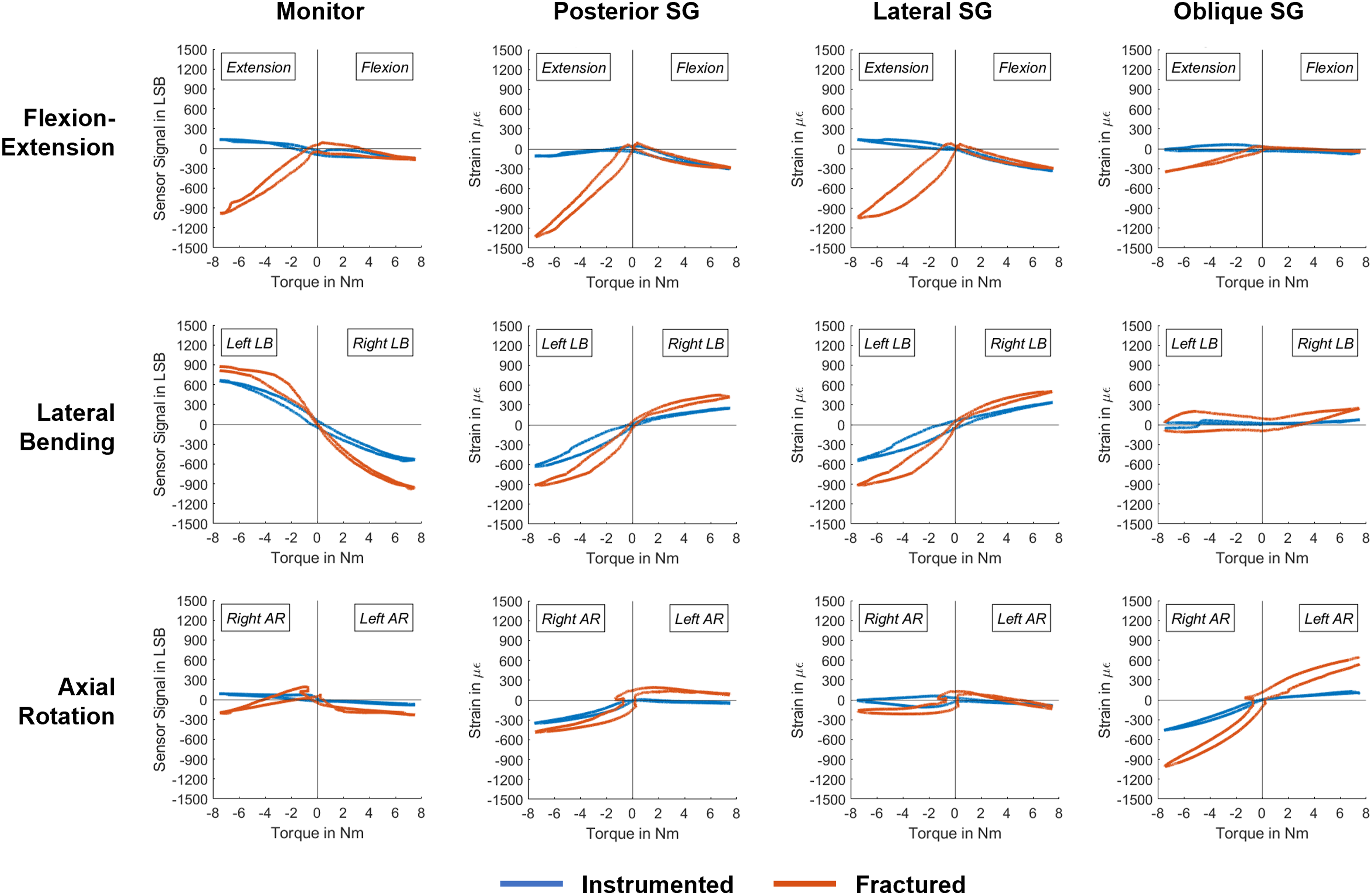
The Monitor registered the highest significant LSB difference between the instrumented intact and fractured spine in FE (771 ± 354 LSB), followed by LB (618 ± 538 LSB). The gain for the posterior SG was also most prominent in FE (1237 ± 470 µε), followed by LB (549 ± 376 µε) and AR (314 ± 294 µε). The strain measured by the lateral SG changed in FE by 398 ± 289 µε. The oblique SG measured a change in strain by 705 ± 409 µε in AR and by 384 ± 300 µε in FE. Other strain and LSB differences were not addressed due to the absence of significant variations.
Exemplary hysteresis curves of implant load data of one specimen are displayed in Figure 5. Following complete disruption of the spinal column, all sensors measured compression for both flexion and extension motions. In contrast, in the instrumented intact spine, extension motion primarily resulted in tensile surface strain. In LB, the posterior SG and the Monitor showed equal but opposite loading patterns. With the sensor placed on the convex rod side, a compressive strain was measured, while on the concave rod side a tensile strain was registered. The load pattern of the posterior SG and the lateral SG were similar across all loading types.
Discussion
In this study, alterations in load distribution of a posterior spine instrumentation were quantified through SG measurements on one of its rods before and after full disruption of L3 vertebra. Simultaneously, an attachable Monitor implementing SG technology was employed for implant load measurement on the contralateral rod. The findings establish the efficacy of the Monitor in quantifying load changes in an ex vivo setting, discerning differences between an intact vertebra and one that is disrupted from posterior to anterior – a situation that could potentially occur after severe flexion-distraction trauma of the spine. Moreover, the study verified the accuracy and reliability of the collected data from the Monitor by conducted SG measurements. This cross-validation approach ensures the consistency and validity of the load measurements, further supporting the reliability of the implantable Monitor.
Transosseous disruption of the posterior tension band and the vertebral body adds significant instability to the spine that cannot be completely compensated by the posterior instrumentation, despite its consideration as a three-column stabilization. 3 The increase in spinal instability after fracture creation of posteriorly instrumented specimens in the current study was detected by a significant increase of the load transfer to the screw-rod construct, leading to considerably more deformation of the rod under loading. By implication, in an in vivo situation this would mean that the load on the posterior instrumentation would decrease in the course of an uneventful healing. Although the fragments of L3 can bear load in flexion by compressing them, the load in extension is taken up by the posterior instrumentation. It can be suspected that the magnitude of implant load change during extension would be less pronounced in vivo, as other structures, such as muscles, play a crucial role for stability of the spine compensating for the loss of other structures.22-24
During testing, the largest difference in strain occurred at the sensor situated posterior to the rod during FE motion. As fixators are in vivo primarily loaded in flexion bending moments and axial compression, 25 this sensor alignment would also be most suitable for a clinical application. In this posterior location, the SG was able to discern shifts in implant loading not only during FE, but also during LB and AR. Nevertheless, sensors, placed on the lateral side of the rod, would also be able to pick up load changes in FE, reducing the necessity to position the sensor precisely posteriorly. To detect load changes during twisting of the spine, mounting the SG at a 45° angle to the rod axis would not be necessary, even though the measured strain would be higher compared to an axial aligned SG on the posterior side. A SG orientation perpendicular to rod axis was ruled out from the beginning, as shear forces acting on the rod are expected to be small 25 and difficult to detect through surface strain measurements using quarter-bridge SGs. The SG measurement results confirmed the current Monitor setup, where the SG is aligned between the two screw holes and as a result of attachment by default in line with the rod’s axis.
Cripton et al 26 investigated load differences of a posterior instrumentation after resecting different spinal structures in the lumbar spine. The median ROM measured in the instrumented intact spine in their study closely matched the average ROM measured in the current work, with a difference of no more than 0.74° in all motions. The largest increase in motion following discectomy was observed in AR, which aligned with the average motion observed in the fracture model examined in this study (within a 6 % difference). This suggests that both discectomy and transosseous disruption of the spinal column produce similar instability in AR due to anterior column damage. In those cases, a long-construct posterior instrumentation (spanning two segments below and above the fractured vertebra) is often recommended because it provides better stability, especially in AR. However, the advantages and disadvantages of long and short constructs are controversially discussed.27,28 Furthermore, Cripton et al found that the magnitude of loading on the instrumentation within an intact spine was equally opposite for all opposing motions. However, other studies indicated that this may only be the case for LB and AR, which is in line with our results.23,29 Similar to our ex vivo findings, by using in vivo collected data Rohlmann et al. were able to demonstrate that when the spine was exposed to LB motion, implant load increased on the one side and decreased on the other. 29
The Monitor used in this study was originally developed to assess fracture healing of long bones.16,17 However, its potential for evaluation of posterolateral fusion of the spine was demonstrated by Windolf et al and Heumann et al in ovine studies assessing the progression of fusion over 16 weeks.18,19 A crucial aspect of these studies was the Monitor’s capability for continuous data acquisition throughout the entire healing process, enabling the collection of daily average implant load data. This facilitated the measurement of relative changes in implant loading over time. The findings of these previous studies align with our ex vivo study on fracture healing of the spine, suggesting that not only the presence or absence of fusion but rather fracture healing without fusion influences implant loading in the spine.
The study had certain limitations in its methodology. As the strain on the rod’s surface was only gauged with the aid of a single SG in a quarter Wheatstone bridge, it was not possible to derive from the data whether the observed compression or tensile strain was caused by axial loads on the rod or due to a bending moment. Although the findings of previous studies indicate that the rod is primarily subjected to bending loads,29,30 the test setup employed in the current work limits the ability to confirm this assumption. Nevertheless, within the scope of this study, one-dimensional surface strain measurement was sufficient to analyze the load changes on the posterior instrumentation as a result of destabilization of the spine.
While pure bending moments applied to the spine in vitro can effectively replicate the forces and moments on the posterior instrumentation seen with an intact spinal segment, 30 the inclusion of a follower load is particularly relevant for non-intact specimens to simulate fixator loads found in vivo. 23 The purpose of a follower load during spinal testing is to simulate the weight of the upper body in combination with the stabilizing effects of the muscles, thereby providing a more accurate representation of spinal loads. Nevertheless, the correct magnitude of follower load, that varies with different motions and patient-specific factors,31–33 is challenging to accurately apply in vitro and maintain throughout the loading process. 34 When done incorrectly, it can introduce significant artifacts, especially in LB and AR, potentially distorting biomechanical data.32–34 Under consideration of these factors, this study utilized pure moments to load the spine, as its objective was to compare relative differences in strain on the rod surface, rather than to quantify the absolute loads. However, the absence of a follower load might have allowed for greater motion, especially in extension, that would occur under similar conditions in vivo. 30 This could result in a more pronounced difference in load on the rod between a fractured and healed vertebra in FE than would be expected in a living patient.
A further limitation was the availability of donors, who were predominantly older individuals, thus increasing the risk of age-related reduction in bone quality and quantity. Poor bone quality could affect screw anchorage and potentially lead to screw loosening, resulting in less load on the rods due to the weak bone-screw interface. Nonetheless, a significant load change on the instrumentation was observed, suggesting that the quasi-static testing did not impair the screw anchorage. The study utilized a simple fracture model generated through a horizontal cut in vertebra L3, allowing to effectively reproduce the fracture but possibly not fully represent the complexity of real-life fractures, especially bursting of the vertebral body commonly found with flexion-distraction injuries. 7 Reduction of the spine to its normal curvature after a burst fracture typically involves distraction of the fractured segment, potentially leading to a greater change in implant load from the fractured to the healed vertebra due to reduced anterior support. 24 However, in order to avoid implant overload or fatigue failure at the interface between screws and bone, it is advisable to consider anterior column support, even when the IVD and endplates of the injured segment are intact. 26 While the study’s findings offer promising results for a broader clinical application of the Monitor, they should be interpreted within the context of these limitations.
This biomechanical study demonstrates that load on posterior instrumentation varies between a fully transosseous fractured and intact lumbar vertebra when there is no additional anterior column support. When combined with continuous implant load monitoring, which was proven beneficial to assess the relative implant load changes over time,18,19 the Monitor can greatly enhance the assessment of those non-fusion treatments, particularly after flexion-distraction injuries with additional anterior column damage. The early detection of healing could lead to implant removal prior to the standard one-year mark, potentially enhancing spinal mobility, and both the quality of life and patient satisfaction. 7 On the other hand, based on those quantifiable data, it would be possible to detect healing disturbances, such as late healing or implant failure,35,36 early on. However, the sensitivity of the system to detect implant failures has first to be proven in a follow-up study. Moreover, it is important to investigate other fracture types, such as isolated anterior burst fractures, to assess the effect of healing on implant loading when certain spinal structures remain intact. This is particularly important as other structures such as facet joints and interspinous ligaments contribute to spinal stability 22 and therefore could prevent detection of significant changes in load-sharing over the healing period. Furthermore, it should be noted that the posterior instrumentation is still a subject to significant motion and hence loading even after the vertebra has healed. Therefore, timely implant removal should be considered after fracture healing to prevent implant fatigue.
Conclusion
After a complete transosseous disruption (AO B1 type fracture – Chance fracture) of the L3 vertebra, which was stabilized with short-segment posterior instrumentation, the load on the rods was significantly higher compared to the healed state. Innovative implantable sensors could be used to monitor those changes allowing assessment of the healing progression based on quantifiable data rather than CT imaging.
Footnotes
Declaration of conflicting interests
The author(s) declared no potential conflicts of interest with respect to the research, authorship, and/or publication of this article.
Funding
The author(s) received no financial support for the research, authorship, and/or publication of this article.