
Abstract
Study Design
Systematic Literature Review.
Objective
To propose a systematic imaging algorithm for diagnosing posterior ligamentous complex (PLC) injury in computed tomography (CT) and magnetic resonance imaging (MRI) to improve the reliability of PLC assessment.
Methods
A systematic review was conducted following PRISMA guidelines. The Scopus database was searched from its inception until July 21, 2022, for studies evaluating CT or MRI assessment of the PLC injury following thoracolumbar trauma. The studies extracted key findings, objectives, injury definitions, and radiographic modalities.
Results
Twenty-three studies were included in this systematic review, encompassing 2021 patients. Five studies evaluated the accuracy of MRI in detecting thoracolumbar PLC injury using intraoperative findings as a reference. These studies indicate that black stripe discontinuity due to supraspinous or ligamentum flavum rupture is a more specific criterion of PLC injury than high-signal intensity. Thirteen papers evaluated the accuracy or reliability of CT in detecting thoracolumbar PLC injury using MRI or intraoperative findings as a reference. The overall accuracy rate of CT in detecting PLC injury was 68-90%. Two studies evaluate the accuracy of combined CT findings, showing that ≥2 CT findings are associated with a positive predictive value of 88-91 %. Vertebral translation, facet joint malalignment, spinous process fracture, horizontal laminar fracture, and interspinous widening were independent predictors of PLC injury.
Conclusion
We provided a comprehensive imaging algorithm for diagnosing PLC in CT and MRI based on available literature and our experience. The algorithm will potentially improve the accuracy and reliability of PLC assessment, however it needs multicentre prospective validation.
Keywords
Introduction
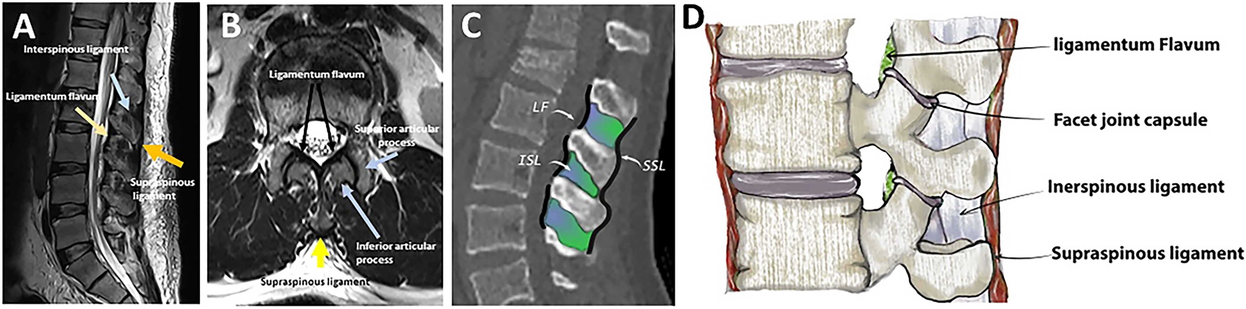
The posterior ligamentous complex (PLC) is a four-structure complex that includes the supraspinous ligament (SSL), interspinous ligament (ISL), ligamentum flavum (LF), and facet joint capsules (FC) ( Figure 1).
1
PLC disruption can cause late-onset kyphosis and chronic back pain and is thus better treated surgically.
2
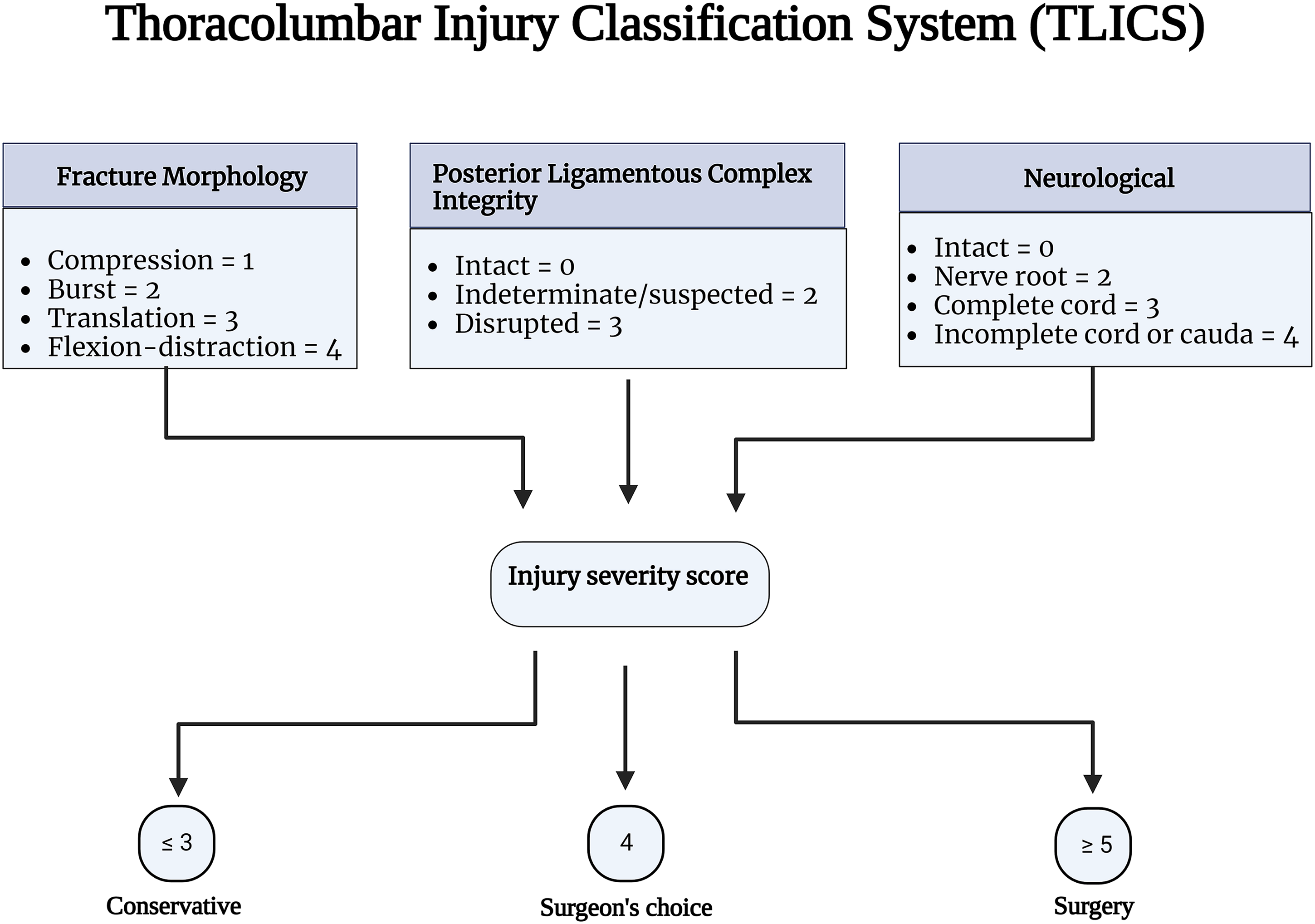
Thoracolumbar injury classification system (TLICS) and AOSpine classification have recognized PLC integrity as a critical component in fracture classification and treatment algorithms.3,4 PLC integrity is one of three key elements of TLICS, along with fracture morphology and neurological condition, that contribute to injury severity score and decision-making ( Figure 2).
3
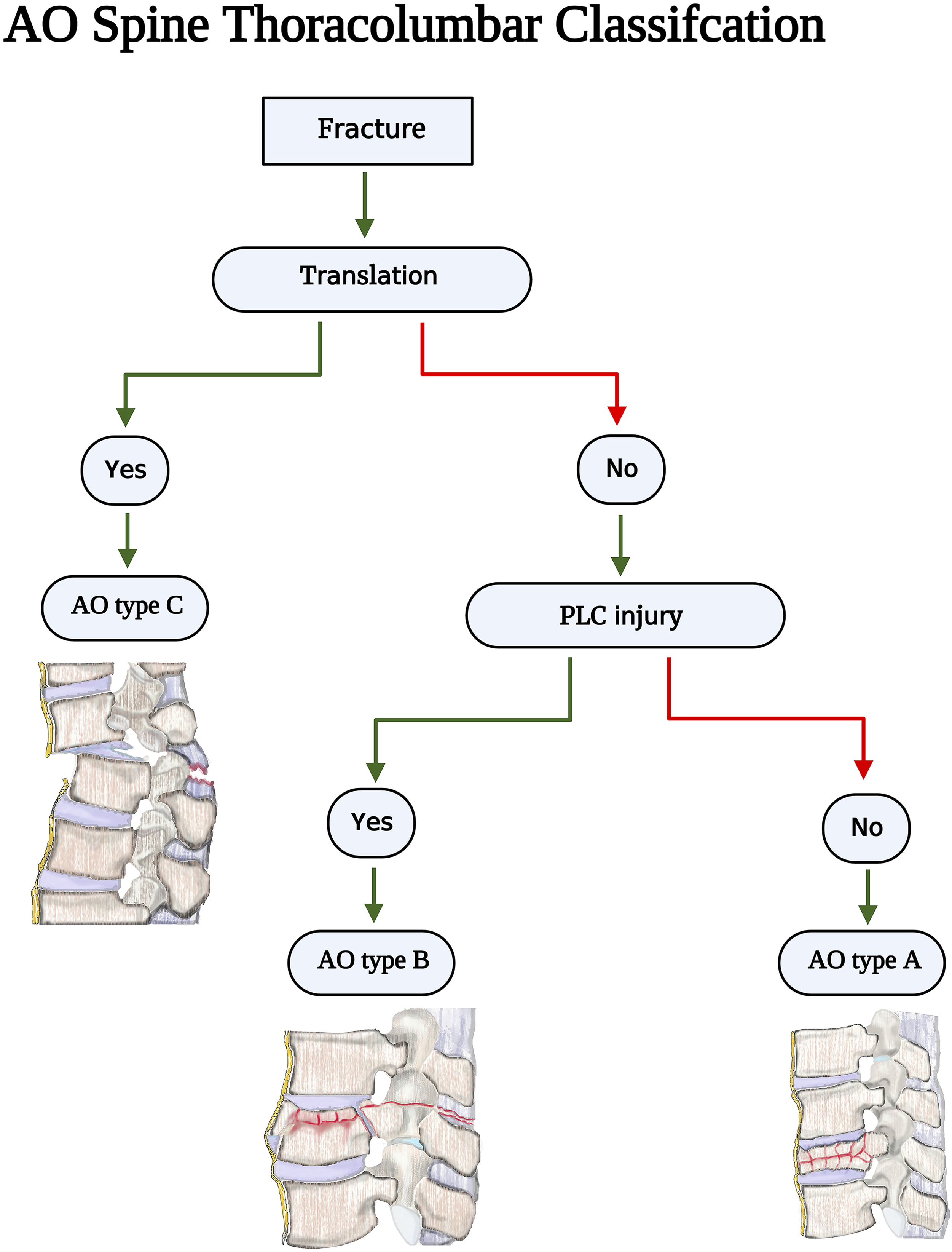
Additionally, PLC integrity is the primary criterion for distinguishing AO type B fractures (tension band injuries) from AO type A (compression fractures without evidence of PLC injury) injuries ( Figure 3).
4
Gross and imaging anatomy of the thoracolumbar posterior ligamentous complex. The thoracolumbar injury classification scheme Source- reference.
3
AOSpine Thoracolumbar classification imaging algorithm. Source - reference
4
There is much debate about the best imaging modality for PLC assessment.1,5 MRI allows direct visualization of PLC structures with high sensitivity and is considered the reference study. 6 Conversely, CT can only detect secondary signs of PLC injury such as vertebral translation or facet diastasis and has a moderate accuracy (50-80 %) and reliability.1,7–10 Important logistical considerations are involved in comparing CT and MRI scans for PLC assessment. 11 Compared to CT, the routine use of MRI in trauma settings was limited by poor availability, higher cost, poor feasibility for polytrauma patients, and considerably longer scanning time. 12 Recognizing these limitations, the current TLFs' classification, such as AOSpine and TLICS, were based on CT.
The PLC assessment has been consistently reported to be the most unreliable component of the AOSpine and TLICS.13,14 The poor reliability in PLC assessment resulted in a bias in the clinical decision-making of TLFs and limited the generalizability of research in this area.15,16 The low reliability of PLC assessment might be attributed to the lack of consensus-based criteria for defining PLC or a standardized method for image interpretation. 12 Poor reliability is caused by a lack of standard definitions for CT/MRI findings, the best imaging planes/sequences, and the pitfalls and pearls of image interpretation. 12 We propose a systematic imaging algorithm to diagnose thoracolumbar PLC injury based on available literature to improve the previously reported poor reliability.
Methods
This systematic review follows the Preferred Reporting Items for Systematic Reviews and Meta-Analyses (PRISMA) Statement. No funding was received for this study, and patient consent was not required since no identifiable health information was collected, and only published studies were incorporated. We conducted a query of the Scopus database from inception until July 21, 2022, using combinations of the words “posterior ligament/ligamentous complex,” “thoracolumbar,” and “injury.” To ensure the inclusion of all available evidence, we also searched the references of available studies for any studies that met inclusion criteria.
Study Eligibility
Studies were included if they described the accuracy or utility of CT or MRI in assessing the PLC injury in the thoracic, lumbar, or thoracolumbar traumatic fractures. Studies were excluded if (1) a full text of the article could not be obtained, (2) the article was written in a language other than English, (3) they were review papers, (4) they were cadaveric or non-human studies. Authors independently screened the abstracts and titles of identified articles. Any articles not meeting exclusion criteria were automatically included for full-text review. At the full-text stage, articles were screened for inclusion based on the predetermined inclusion criteria. A more senior author reconciled discrepancies.
Data Collection Quality Assessment
The authors extracted data from the included studies with a self-designed table. Contents of data selection included objectives, injury definitions, radiographic modalities, and key findings of included studies. Due to significant data heterogeneity, variability in outcome measures and study objectives, and the different imaging modalities utilized, a meta-analysis of the findings was not performed.
Results
Search Results
The initial Scopus search identified 408 articles, after which the title and abstract screening identified 72 potentially relevant articles (Figure 4). Twenty-three articles encompassing 2021 patients were included after full text and citation review. Twenty-two studies were excluded because they did not assess the clinical utility of CT or MRI for assessment of the PLC, 13 were excluded because they did not evaluate traumatic PLC injury, four were excluded for analysis of the cervical spine, and nine were excluded because they were surveys, case series, or review articles. Reasons for excluding other articles are further detailed (Figure 4). Four additional studies were identified through a reference review of included studies. The characteristics and key findings of included studies are detailed (Figure 4). PRISMA Flow Diagram Describing Article Selection for Inclusion. Abbreviations: PRISMA, Preferred Reporting Items for Systematic Reviews and Meta-Analyses.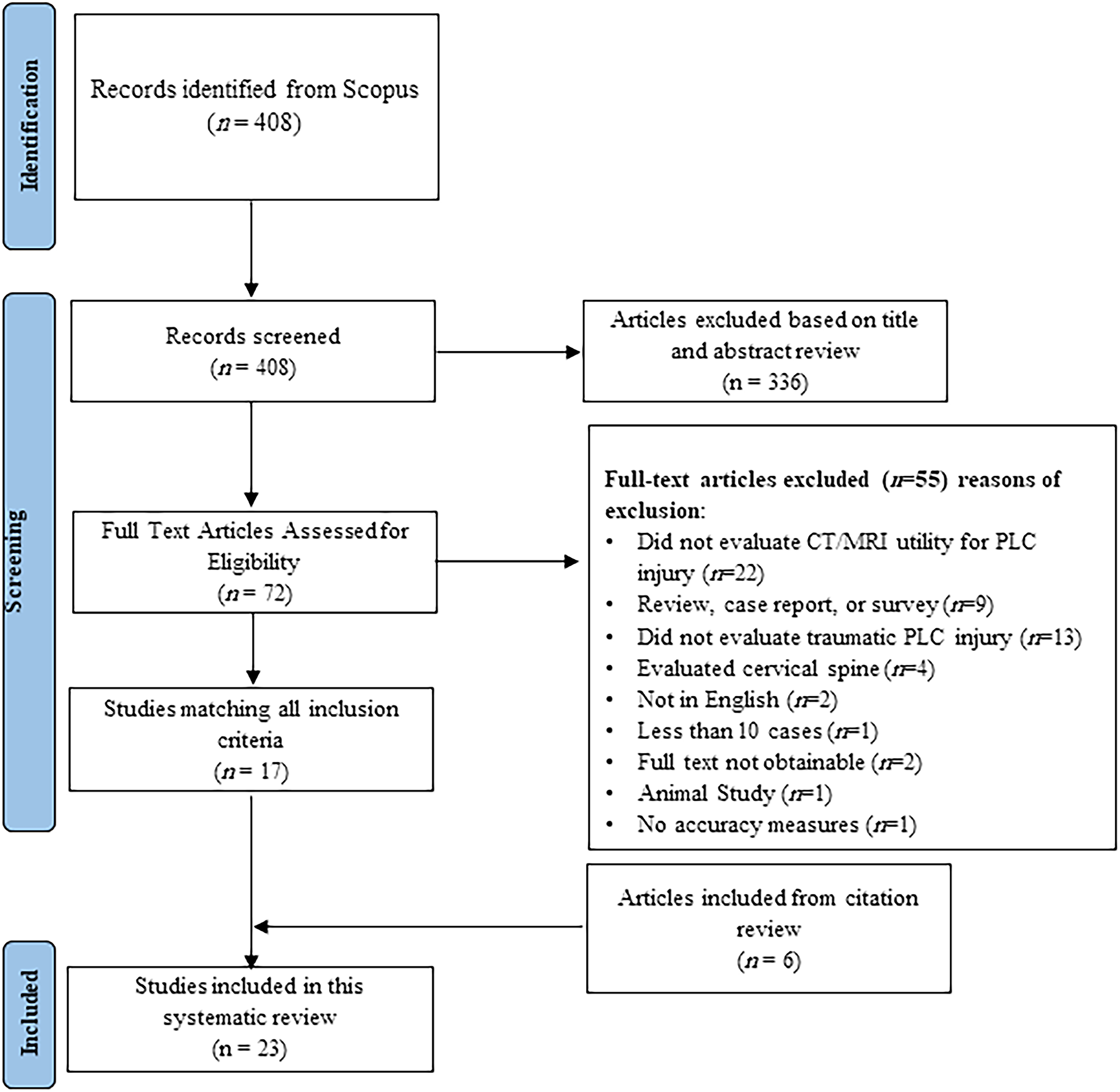
MRI Accuracy or Reliability in Detection of PLC Injury
Studies on the Accuracy or Reliability of Magnetic Resonance Imaging in Diagnosis of Posterior Ligamentous Complex injury.
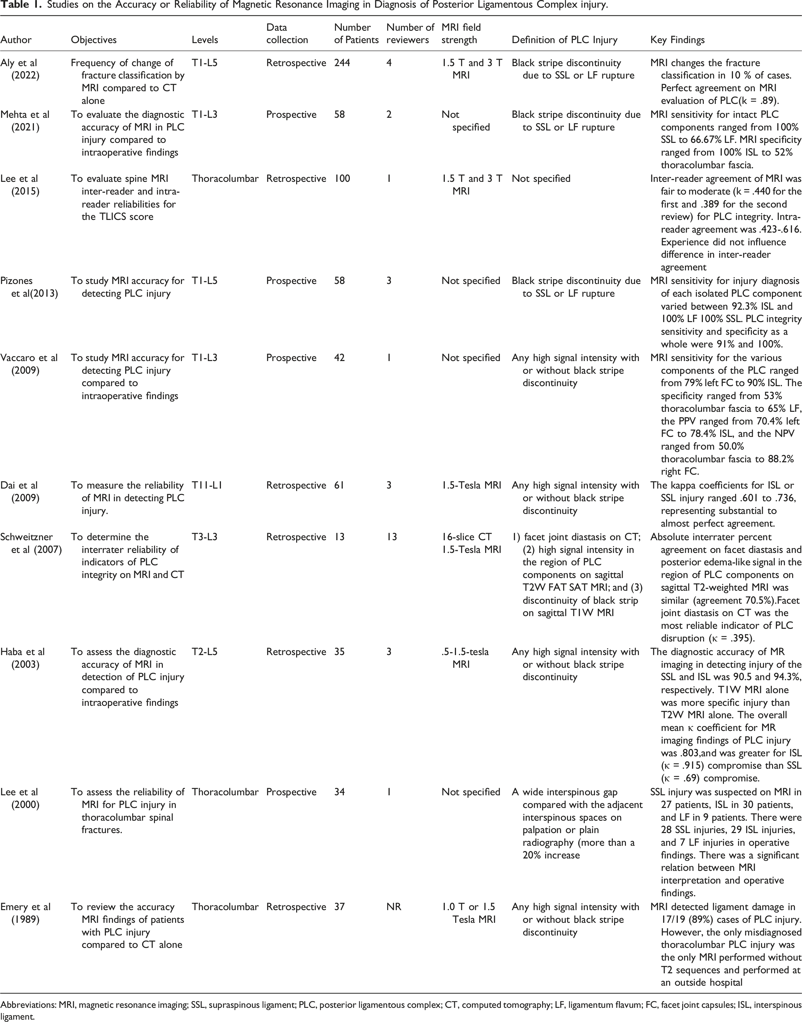
Abbreviations: MRI, magnetic resonance imaging; SSL, supraspinous ligament; PLC, posterior ligamentous complex; CT, computed tomography; LF, ligamentum flavum; FC, facet joint capsules; ISL, interspinous ligament.
CT Accuracy or Reliability in Detection of PLC Injury
Studies on the Accuracy or Reliability of Computed Tomography in Diagnosis of Posterior Ligamentous Complex Injury.
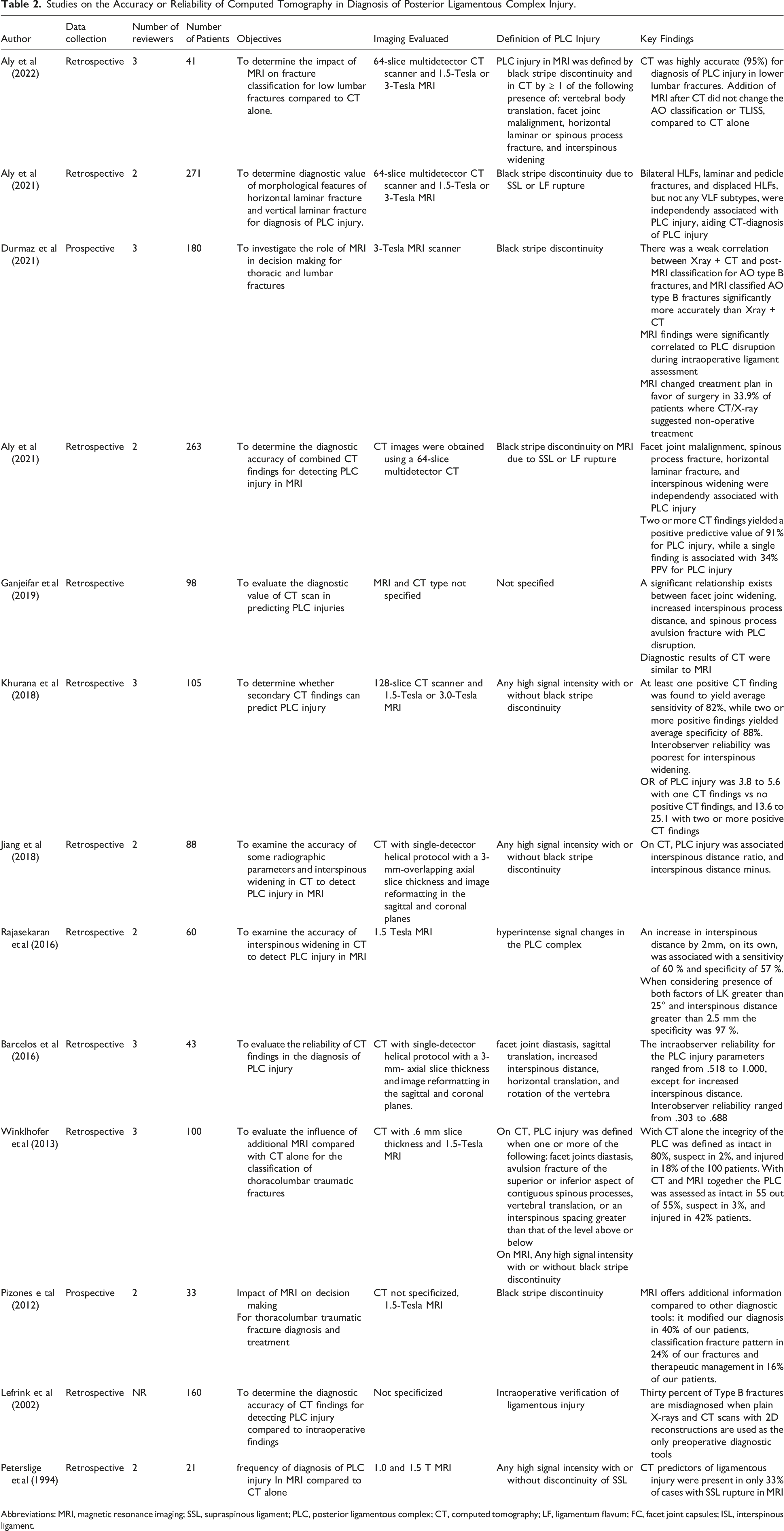
Abbreviations: MRI, magnetic resonance imaging; SSL, supraspinous ligament; PLC, posterior ligamentous complex; CT, computed tomography; LF, ligamentum flavum; FC, facet joint capsules; ISL, interspinous ligament.
Discussion
The integrity of PLC has been cited as a critical element in the TLFs' classification and treatment algorithm by AOSpine classification, but no standard approach for PLC evaluation in CT or MRI has been provided.3,4 As a result, the reliability of PLC assessments and TLFs' classifications were compromised.13,14 Herein, we propose an algorithm for CT/MRI evaluation of a thoracolumbar PLC injury that incorporates a systematic literature review's results and authors' clinical expertise. The systematic review of the literature centered on the diagnostic accuracy and reliability of CT and MRI in PLC injury. Following is a summary of the significant CT and MRI findings for diagnosing PLC injury.
MRI Protocol and Imaging Considerations
The importance of using the optimal MRI sequence parameters cannot be overemphasized. 25 However, these parameters vary greatly depending on the MR imaging system’s field strength, coil design, and gradient strength; a customized approach is needed for each MRI device. 25 The spine trauma protocol includes axial and sagittal T2-WI and T1-WI, sagittal short tau inversion-recovery (STIR), with a slice thickness of 3 mm for sagittal and 4 mm for axial, using a matrix size of 240x320.7,26 T2-weighted fat-suppression sequences such as STIR or fat-saturated T2-weighted sequences are needed to distinguish T2 hyperintensity associated with PLC injuries from adjacent fat. 27 Compared to the fat-saturated T2-weighted sequence, the STIR sequence provides more uniform fat signal suppression and is less affected by the presence of metallic implants; however, it takes slightly longer to acquire and frequently produces a grainier image. 27 There is no evidence that a 3 Tesla (T) MRI scanner is more accurate than a 1.5 Tesla scanner in detecting PLC injury. One study revealed comparable inter-intrareader reliability for 1.5 and 3T. 12 A focused MRI protocol of three levels above and below known TLF has shown a comparable sensitivity to a whole-spine MRI in detecting clinically significant injuries while reducing scanning time. 28 For MRI to be highly sensitive for PLC injuries, it should be performed within 72 hours of injury. After this point, MRI’s sensitivity decrease due to resorption of the T2 signal hyperintensity produced by edema or hemorrhage, which provides an excellent contrast medium to the low signal intensity ligaments. 25
CT Protocol and Imaging Considerations
The CT's perceived image quality and the diagnostic performance depend on the choice of imaging parameters and the post-processing, in particular the reconstruction algorithm use the reformatting parameters. 29 The following parameters are recommended for a 64-slice MDCT scanner in a helical mode: 120 kVp, MA 150-600 smart MA, and pitch and speed (mm/rot) 1.375:1/55.00. The slice thickness for axial images of soft tissue and the bone algorithm was 5 mm and .625 mm, respectively, and 3 mm or less for reformatted images.12,30
MRI Findings for Each Component of PLC
Imaging Anatomy of the Posterior Ligamentous Complex
Magnetic Resonance Imaging Findings of Thoracolumbar Posterior Ligamentous Complex Injury.
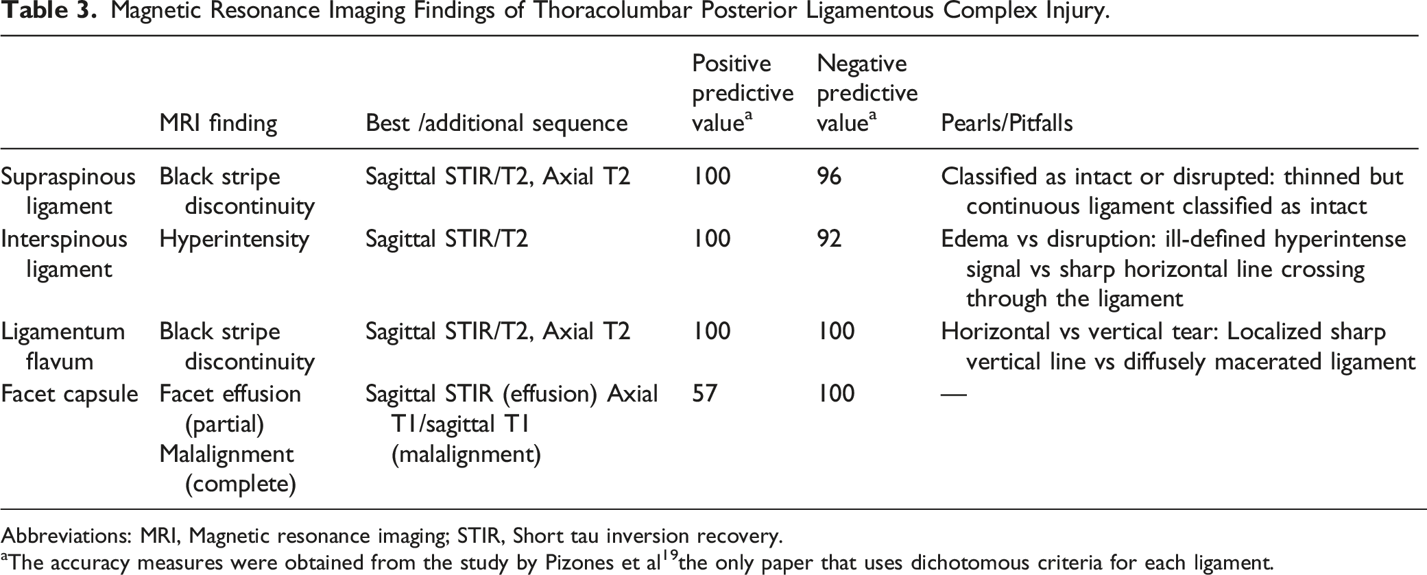
Abbreviations: MRI, Magnetic resonance imaging; STIR, Short tau inversion recovery.
aThe accuracy measures were obtained from the study by Pizones et al 19 the only paper that uses dichotomous criteria for each ligament.
Supraspinous Ligament
The MRI identification of SSL injury has the highest accuracy for detecting SSL injury intraoperatively (PPV,100% and NPV. 96%, Table 3).
19
According to Pizones et al, PLC disruption due to distraction injury follows an orderly rupture progressing from posterior to anterior; therefore, SSL rupture is the inflection point that marks PLC's incompetence.
31
SSL rupture can be observed as discontinuity of the black stripe, which is best seen in sagittal STIR/T2 images and corroborated by the absence of SSL-related signal intensity in axial T2 images. (Figures 5A and B)
26
Occasionally, axial T2 may show SSL is avulsed from the tip of the spinous process. (Figure 5C) SSL and LF injuries are typically graded as “intact” or “disrupted”; hence a thinned but continuous SSL or LF should be reported as “intact” (Figure 5D).
32
Detecting a ruptured SSL in the mid-thoracic area may be more challenging due to anatomical variations in the SSL/ISL complex.6,26,33 Vascular marking due to a blood vessel crossing the black stripe should not be mistaken as black stripe discontinuity (Figure 5E). Magnetic resonance imaging findings in supraspinous ligament injury. 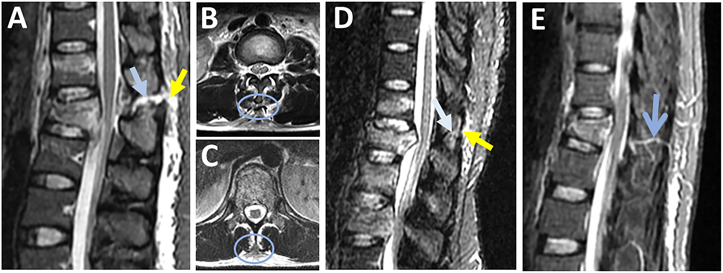
Ligamentum Flavum
LF rupture can be observed as "black stripe discontinuity," which is best seen in parasagittal T2 or STIR images. It is critical to distinguish between a horizontal LF tear (which indicates incompetent PLC) and a vertical LF tear, considered stable (Figures 6A and B).
34
On axial T2 images, horizontal LF tears are visible as diffusely macerated ligaments, whereas vertical LF tears appear as unilateral focal (Figures 6B and C). Furthermore, horizontal LF tears appear on several sagittal STIR slices, whereas vertical tears are barely found in a single slice. (Figure 6E) According to the orderly sequence of PLC rupture by Pizones et al, a horizontal LF caused by the distraction mechanism is typically accompanied by SSL/ ISL rupture and represents the advanced stage of PLC incompetence.
31
Contrarily, a vertical LF tear is typically caused by a vertical laminar fracture due to axial compression and is not associated with other ligamentous injuries.
34
Magnetic resonance imaging findings of ligamnetum flavum injury. 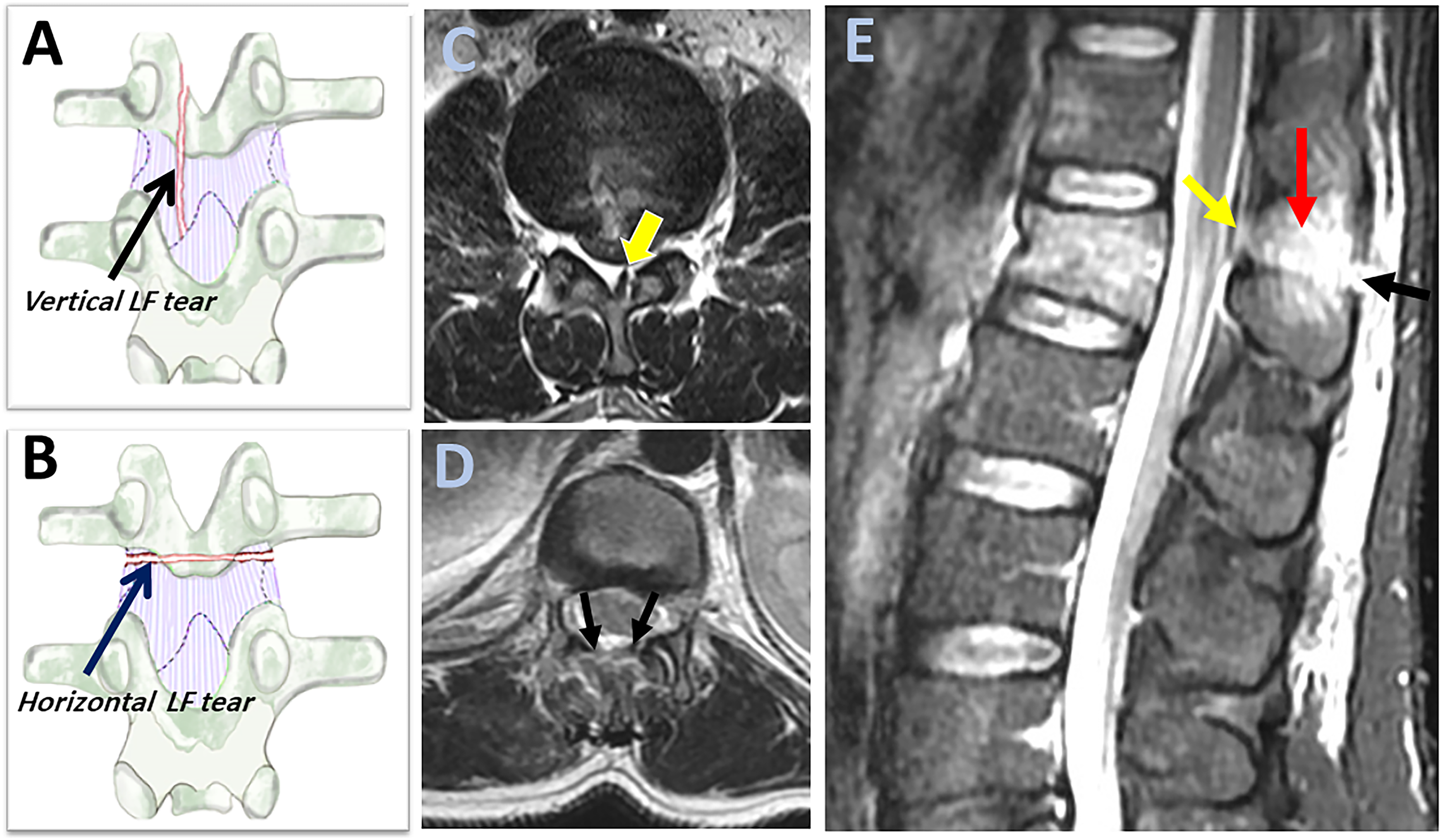
Interspinous Ligament
ISL is best evaluated using sagittal STIR or T2 image, which may show hyperintensity for both ISL edema and rupture. ISL edema can be differentiated from ISL rupture by the ill-defined hyperintensity as opposed to the sharp horizontal line across the ligament.
31
However, the low contribution of ISL to PLC competence makes the distinction between ISL edema and rupture of little practical importance (Figure 7A and B).
35
Magnetic resonance imaging findings of interspinous ligament injury. Sagittal STIR images show 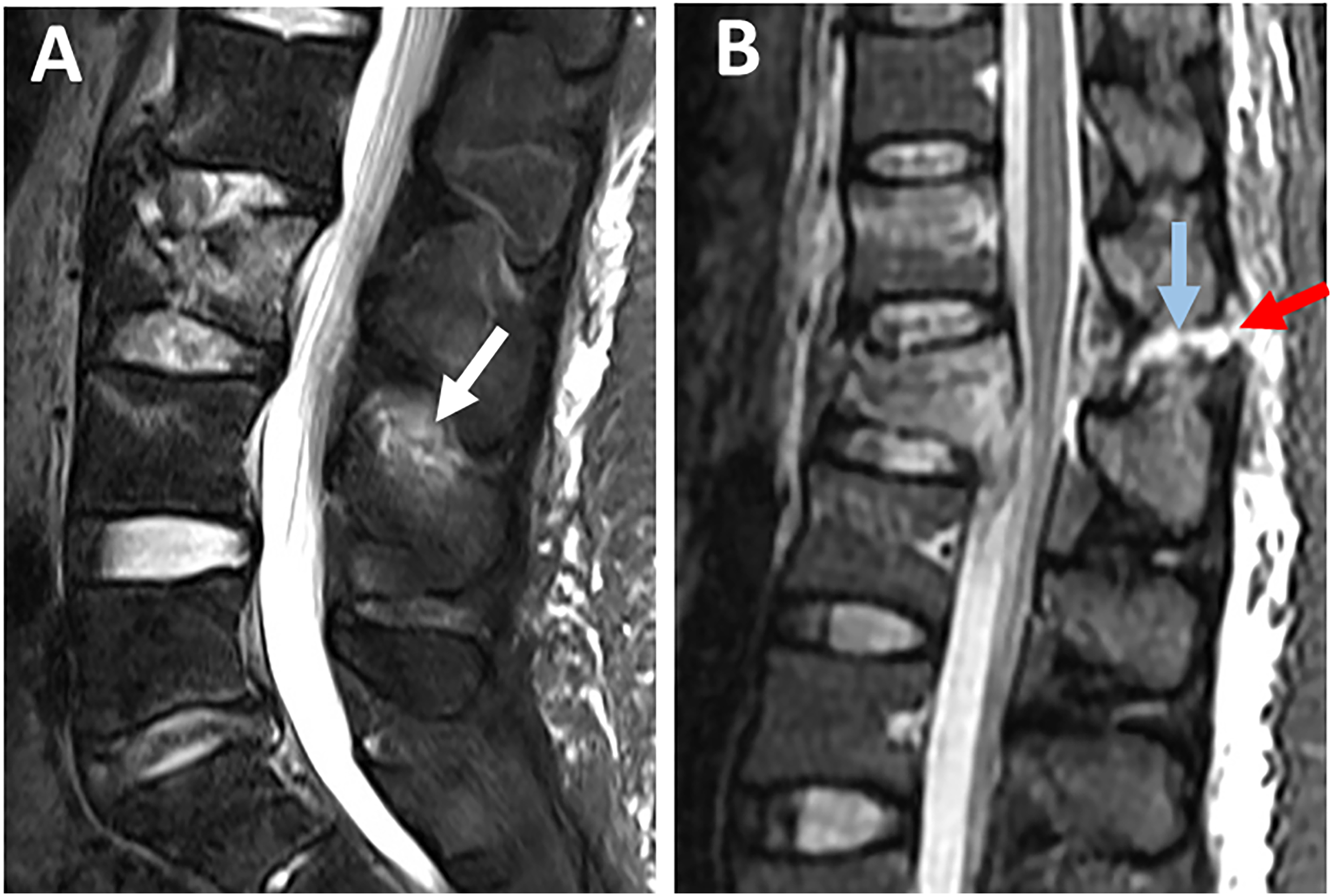
Facet Joint Capsule
Facet joint effusion and widening represent partial capsular ligamnt injury and can be seen as hyperintensity on axial STIR or T2 images (Figures 8A and B). In contrast, facet dislocations, which indicate complete injury, are better visualized in T1 axial/sagittal images because of their high anatomical resolution (Figures 8B and D).
31
Thoracic facets' effusion is most easily seen on STIR sagittal sequences, which are perpendicular to the thoracic facets' coronal orientation. T2 axial scans, on the other hand, were the most helpful in identifying a sagittal-orientated lumbar facet injury.
26
Although FC is a major contributor to PLC competence, less emphasis was put on its MRI assessment due to low specificity (52%, Table 3).
19
Magnetic resonance imaging findings of facet capsule ligament injury. Axial T2-weighted images 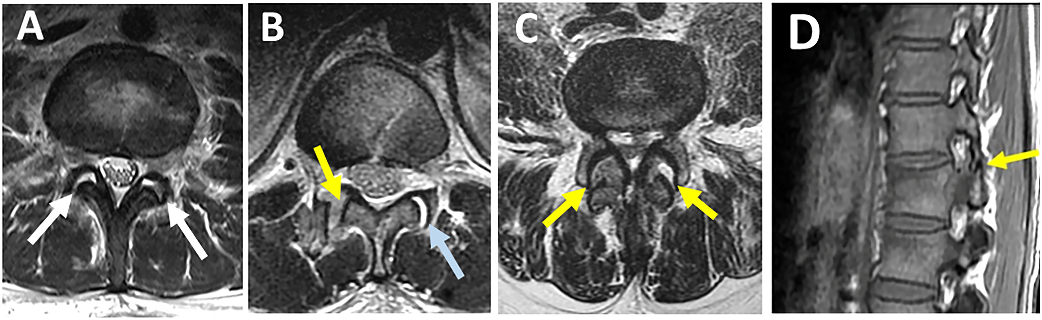
Thoracolumbar Fascia
While most research uses a "four-structure" definition of the PLC, Vaccaro et al report the thoracolumbar fascia as a fifth component. The fact that thoracolumbar fascia is the least reliable and specific (53%, Table 3) component of PLC may account for its unpopularity.18,20
Definition of PLC Injury in MRI
There is no agreement on the definition of PLC injury in MRI regarding the number of components damaged or the degree of damage (rupture vs edema). 1 There is a debate whether to define PLC injury as “black stripe discontinuity” due to SSL or LF rupture or High-signal intenisty (HSI), a broader criterion that includes any hyperintensity whether or not associated with “black stripe discontinuity”. Earlier research found HSI to be highly sensitive in detecting PLC injury when using intraoperative findings as a reference.17,36 Recent research suggests HSI may overread PLC injury due to a high false positive rate. 18 On the other hand, black stripe discontinuity demonstrated high specificity in detecting PLC injury (Table 3).19,26 Furthermore, biomechanical evidence that SSL and LF are the key components of PLC competence further supports the use of “black stripe discontinuity” to define disturbed PLC.35,37 Despite low specificity, the HSI criterion is still widely used in research, most likely to increase the sample size. 1 HSI may be easier to assess than black stripe discontinuity, which requires examining each PLC component for partial vs complete injury.6,12
MRI’s Pitfalls
A significant drawback of MRI's PLC evaluation is the reported moderate to poor interobserver reliability. 38 Differences in experience or training level could explain the moderate reliability. Another possibility is that radiologists and spine surgeons have different perspectives on the MRI sequence or interpretation. 26 MRI parameters are more challenging to standardize due to their large numbers and device-specific specifications. 25 while black stripe discontinuity is a more specific criterion than HSI; it is still imperfect. Notably, all MRI accuracy studies use intraoperative findings as a reference, restricted to the more severe surgical cases as a spectrum bias. 32 Therefore, MRI findings of PLC injury should be integrated with other findings, including X-ray and CT finidngs. 18
CT Assessment of PLC Injury
Proposed Definitions, Accuracy, and Reliability of Computed Tomography Findings of Thoracolumbar Posterior Ligamentous Complex Injury.
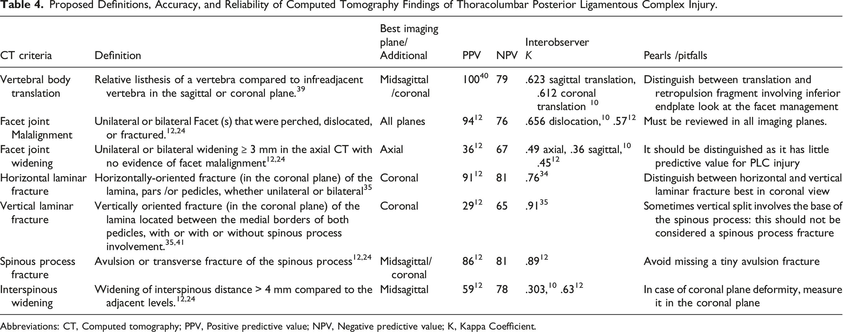
Abbreviations: CT, Computed tomography; PPV, Positive predictive value; NPV, Negative predictive value; K, Kappa Coefficient.
CT Findings of PLC Injury
Vertebral Body Translation
Vertebral body translation (VBT) is the anterior or lateral translation of a cranial vertebra relative to a fractured vertebra, implying severe damage to PLC and the intervertebral disc.4,39 While a standardized method for measuring VBT was reported, there is no agreed-upon threshold for VBT in TLFs (Figure 9A and B).
39
A possible explanation is that any translation in thoracolumbar region, regardless of magnitude, strongly indicates instability.
39
When a severe burst fracture involves the inferior endplate, the retropulsed fragment may migrate posteriorly relative to the caudal vertebra, mimicking translation. In that case, a key point for differentiation is to examine the facet joint to see if it is dislocated or not. Assessment of vertebral translation and interspinous widening in CT. 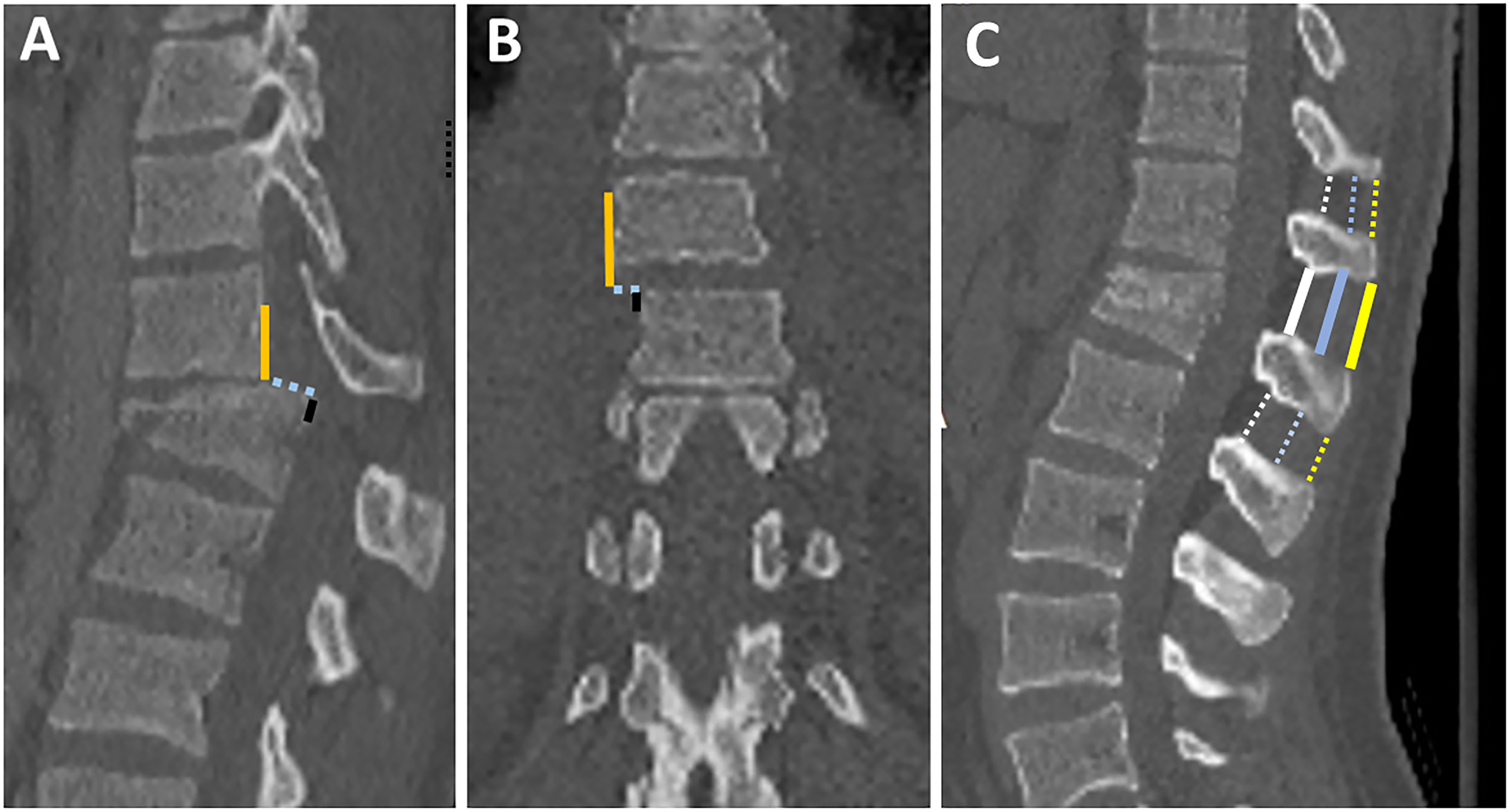
Facet Joint Diastasis
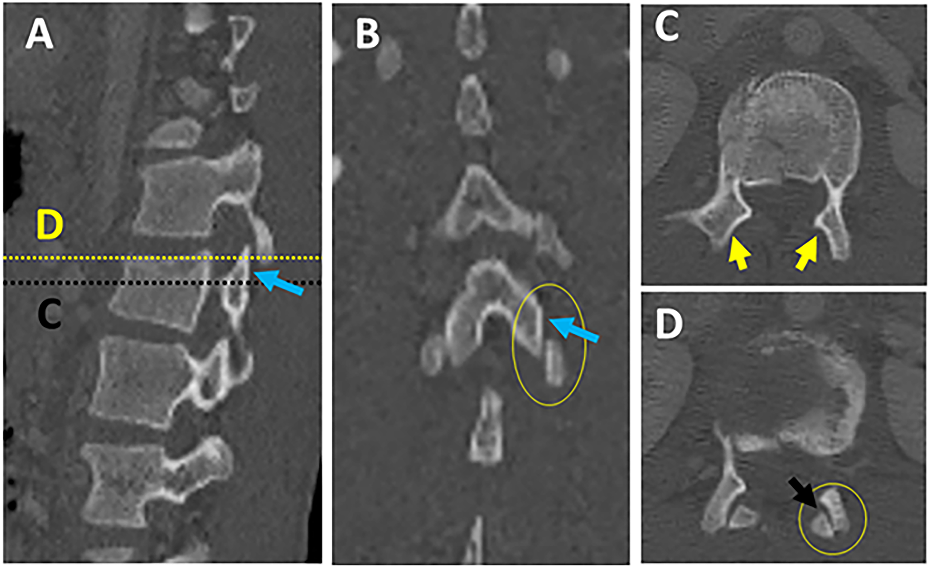
In a survey of expert spine surgeons, facet diastasis was rated as one of the most predictive and reliable CT signs of PLC injury.7,12,14 Facet diastasis refers to a wide spectrum of injuries that includes: facet dislocation (complete uncoverage of articular surfaces), subluxed (partial uncoverage), fractured (displaced or non-displaced), or facet joint widening (FJW) (Figure 10; A-H).12,23 Controversy exists regarding the diagnostic value of subtle facet injuries such as FJW for PLC injury. Two recent studies have demonstrated that FJW > 3mm on axial CT is not a predictor of PLC injury.12,23 Facet subluxation is the most likely morphology to be overlooked for various reasons. First, facet subluxation is classically diagnosed by the naked facet sign that occurs when the inferior articular facets of the cephalad vertebra do not appear adjacent to the superior facets of the caudal vertebra in axial CT images (Figures 11A-D). However, in case of slight vertical distraction, a naked facet sign may appear in only one or few axial cuts and could be easily overlooked.
43
(Figures 12A-D) Additionally, Harris et al pointed out that the naked facet sign can occur due to minor angulation or flexion and does not always indicate the presence of PLC injury.
44
Thoracolumbar facets have a variety of sagittal/coronal orientations, so they may dislocate in any plane and be easily missed unless all imaging planes are carefully examined (Figures 12A-D).
45
Second, facet diastasis may reduce in supine position; however, even when reduced, there is an asymmetry in the facets that can be observed on a careful review of the axial CT images.
7
Various patterns of facet diastasis in CT. Naked facet sign. Multiplanar CT assessment of facet subluxation (A-B). 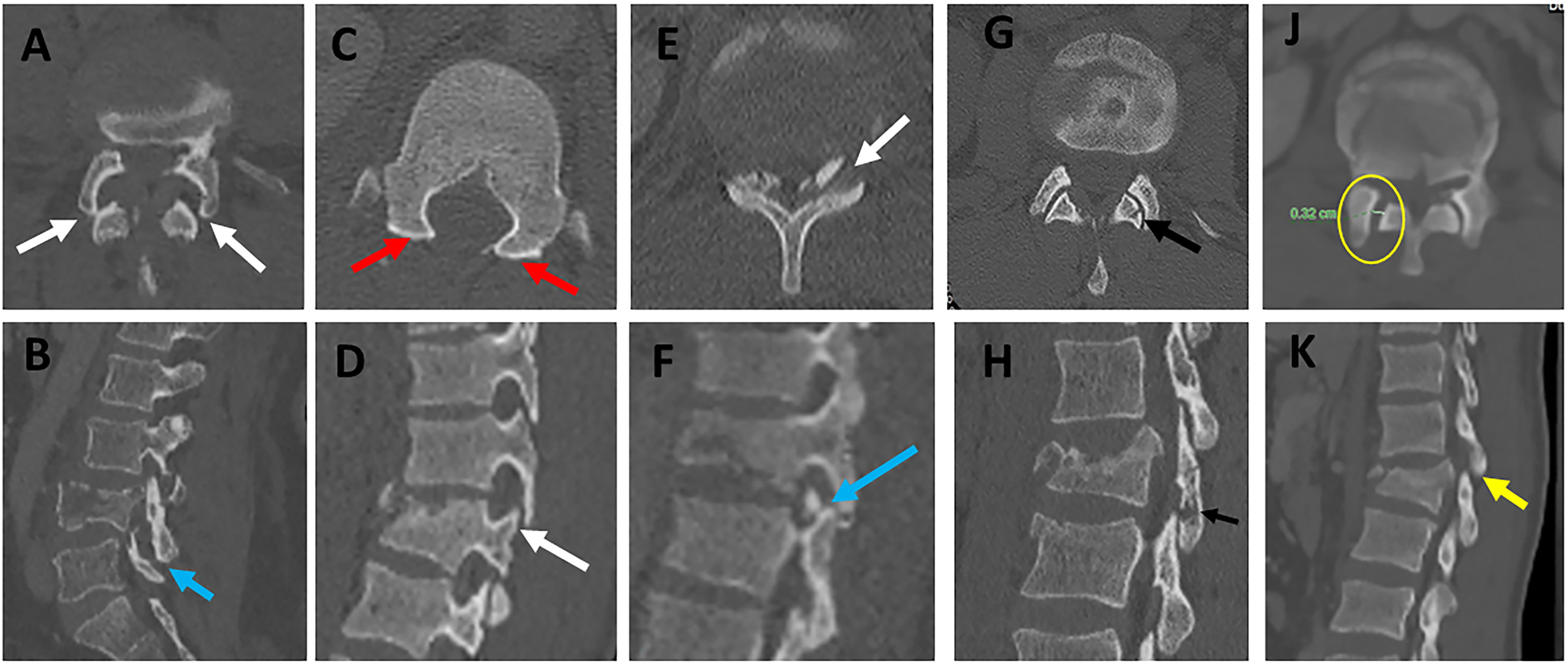
Laminar Fracture
The AOSpine has recognized two types of laminar fractures based on their distinct pathomechanics.
4
Horizontal laminar fracture (HLF) implies a flexion-distraction mechanism of injury, indicating AO type B.
4
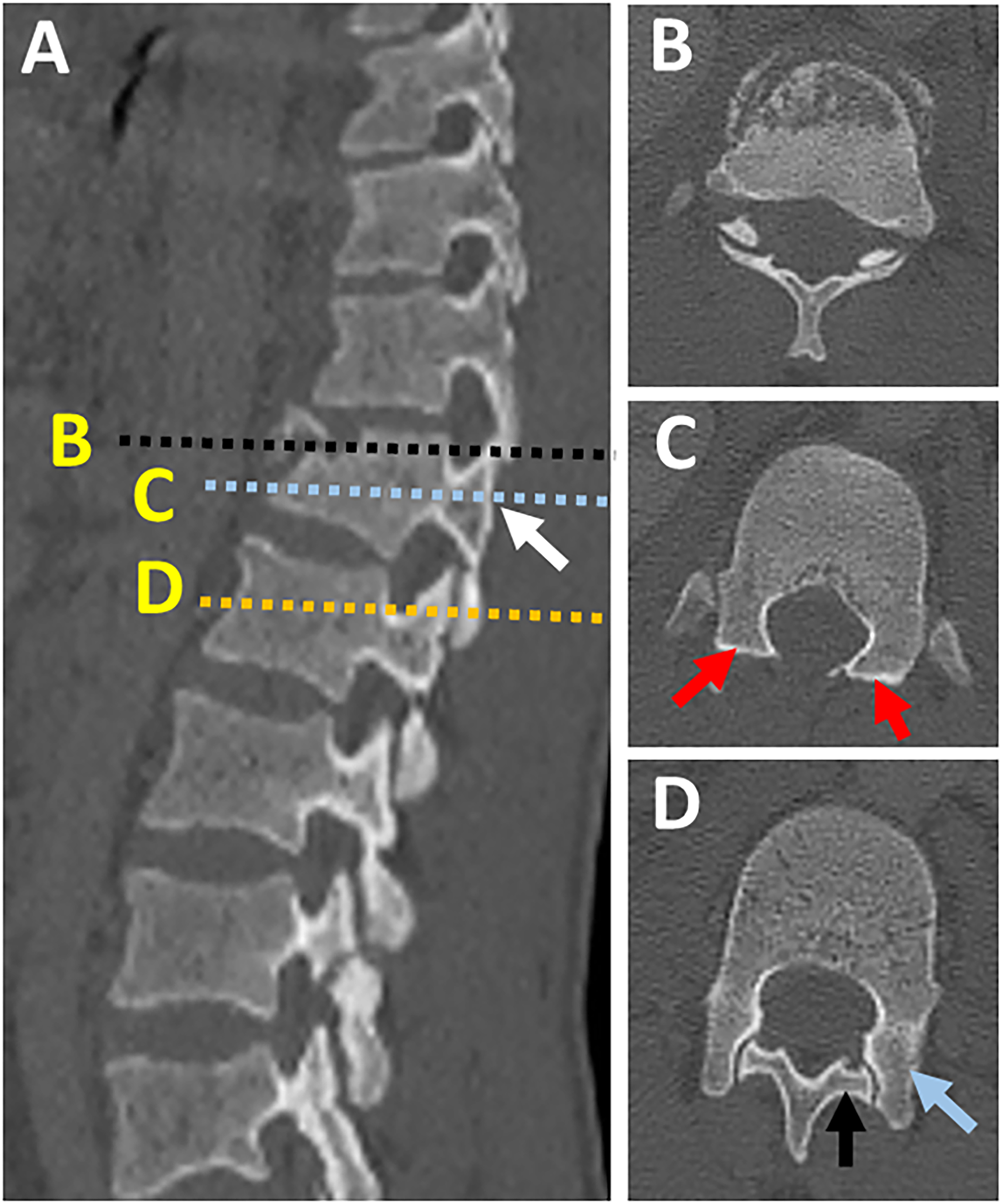
Vertical laminar fracture (VLF), on the other hand, results from severe axial loading with the transfer of energy to posterior elements and vertical split fractures. VLF does not constitute PLC damage; consequently, it is a feature of burst fractures (Figures 13A-K).4,46 According to a recent study, HLF, but not VLF, was independently predictive of PLC injury (PPV of 91% vs 48%).
34
The following features of HLF were highly associated with PLC injury: displacement > 2mm, bilateral laminar fractures, and laminar, and pedicle fractures.
34
A common pitfall is failing to differentiate between HLF and VLF when images are read only in axial images without carefully reviewing the coronal reconstruction images.34,41 Indeed, because of their lower prevalence and horizontal orientation, HLF is more likely to be missed, resulting in missing PLC injury.
34
The 3- columns Denis' concept, which remains popular, implies that all burst fractures with laminar fractures, regardless of type, are unstable, hence undermining the importance of distinguishing between vertical and horizontal laminar fractures.
47
Understanding that HLF and VLF, while morphologically similar, are the footprints of distinct injury mechanisms may help to reduce misinterpretation.
48
The distinction between horizontal and vertical laminar fractures in CT. 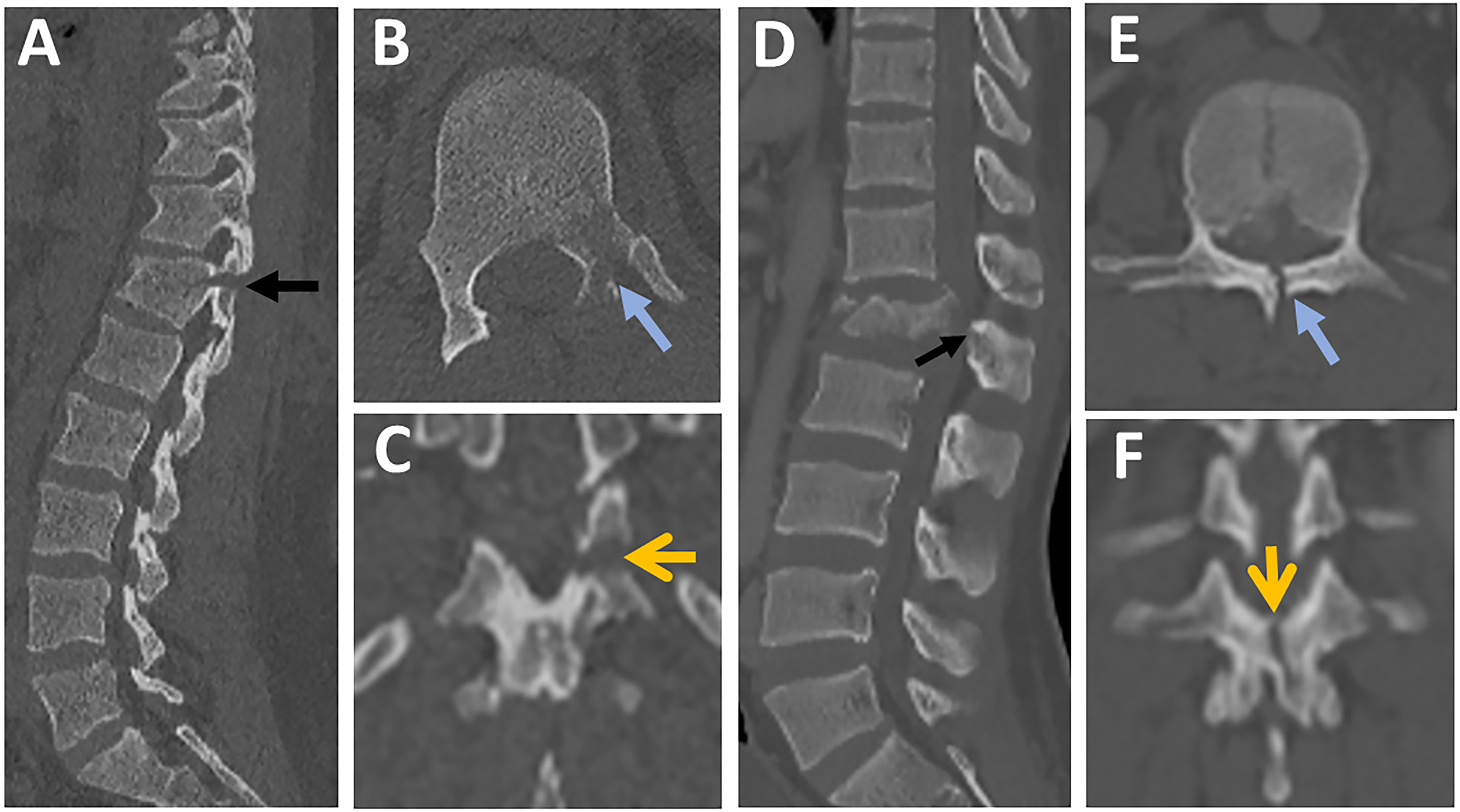
Spinous Process Fractures
Avulsion, transverse, or oblique spinous process fracture (SPF) is one of the most reliable and predictive signs of PLC injury.
12
SPF is best seen in sagittal images, but fractures can be seen in axial, coronal, or sagittal images depending on the orientation of the fracture lines (Figures 14A-D). The most common pitfall is missing or ignoring a tiny avulsion SPF, which is highly predictive of PLC injury (Figures 14B and C). Spinous process base fracture may be caused by a vertical split associated with axial loading, but this does not constitute PLC. It is crucial to differentiate SPF from non-united ossification centers within the spinous process's superior or inferior corner, typically with smooth and well-corticated margins.
49
In osteoporotic patients, SPF can occur even with low-energy trauma and hence are less predictive of PLC injury. Evaluation of spinous process fractures in CT. Midsagittal CT image showing 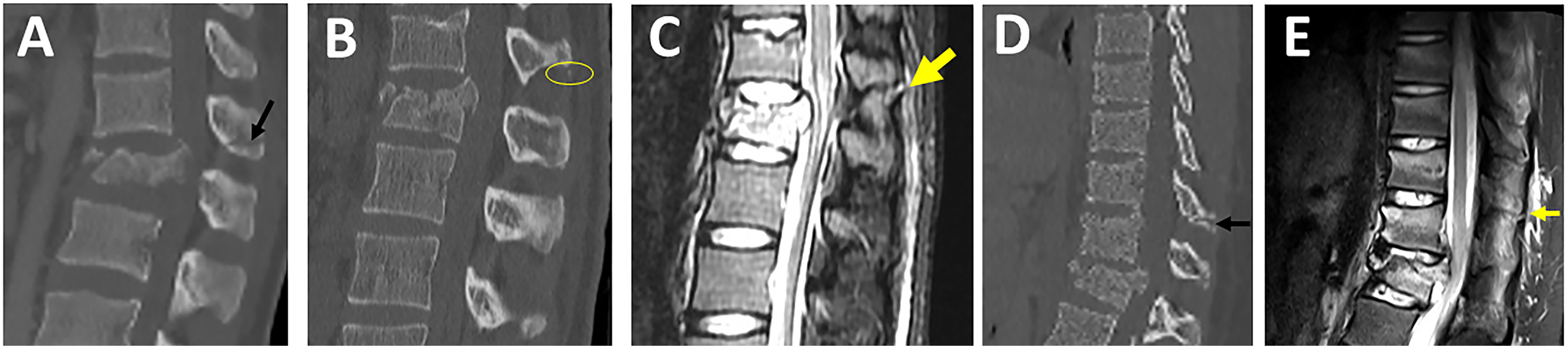
Interspinous Widening
ISW is defined as widening of interspinous distance compared to the adjacent levels, best seen in the midsagittal plane (Figure 9C). 12 Although ISW is considered an important sign of PLC injury; it is the most contentious finding regarding variations in measurement technique or threshold and measurement errors (Figure 9C).7,8,48A wide range of ISW's thresholds (2-7 mm) can be attributed to interindividual and regional differences.50,51 Another explanation is that ISW may vary between supine CT and 48 standing X-ray. Rjasakaran et al reported various ISW's thresholds trade-off sensitivity and specificity and found that > 4 mm yielded a specificity of 90%.7,8,12,50 ISW may be difficult to measure in the presence of out-of-plane coronal deformity; in this case, ISW measurements in coronal images may be beneficial. 39
CT Criteria to Define PLC Injury
The greatest challenge in CT's evaluation of PLC assessment is the lack of agreement on CT criteria for PLC injury.
1
The typical flexion distraction morphology, i.e., horizontal osteoligamentous disruption, is used to diagnose PLC injury in CT.3,4 However, this morphology is frequently lacking, leading to disagreement about PLC status in CT.13,14 Two recent studies have proposed to define PLC injury in CT based on the diagnostic value of combined CT findings.12,23 Such combined analysis reflects the different clinical scenarios encountered in clinical practice; patients may present with one or more CT findings.12,23 Vertebral translation, facet joint malalignment, spinous process fracture, horizontal laminar fracture, and interspinous widening were independent predictors of PLC injury. FJW and VLF were not associated with PLC injury and are most likely responsible for most falsely identified PLC injuries in CT. At least two CT findings have a PPV of 88-91% for PLC injury, suggesting its use as a CT criterion for PLC injury and little added value for MRI testing (Figure 15).12,23 In addition, the absence of all four CT findings provided the best ability to rule out PLC injury (A negative predictive value of 91%).12,23 The presence of single CT findings lacked sufficient PPV or NPV to rule in or rule out PLC injury; hence it can be used to indicate indeterminate PLC injury in CT and the need for further MRI testing. Currently, there are no clear guidelines on when to do an MRI for PLC assessment.
5
MRI has been shown in previous studies to change TLF classification or treatment decisions in up to 30% of cases.22,24 Diagnostic value of combined computed tomography findings for thoracolumbar posterior ligamentous complex assessment.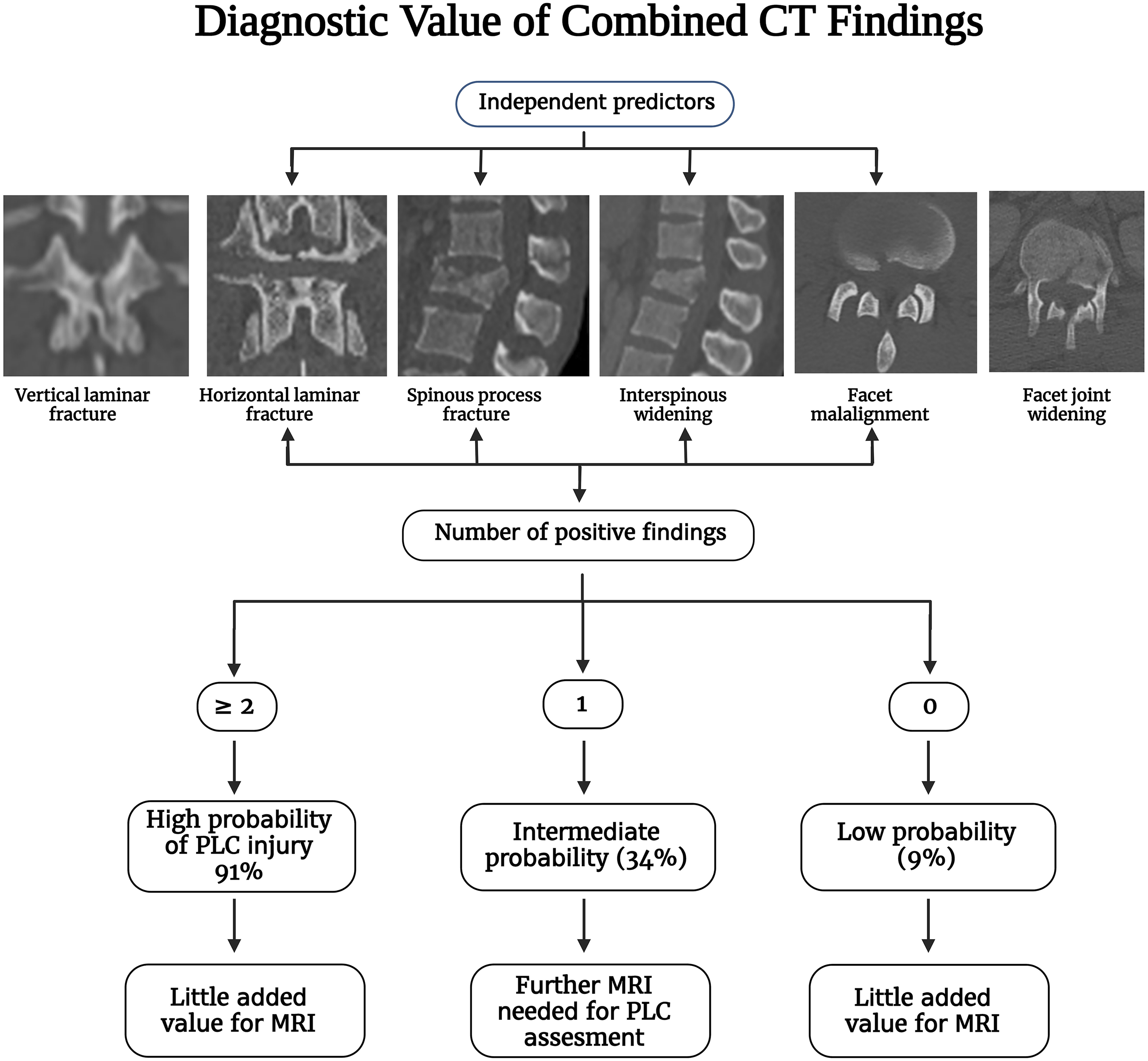
Pitfalls of Interpretations of PLC Injury in CT
Osteoporosis
Osteoporosis may reduce the accuracy of CT in detecting HLF or SPF. Furthermore, osteoporosis may cause osseous injuries out of proportion to PLC injury, lowering the PPV of CT findings for PLC injury. 32 For instance, in osteoporotic patients, SPF can occur even with low-energy trauma and hence are less predictive of PLC injury. However, the impact of osteoporosis on CT accuracy is difficult to assess because not all patients have DEXA scans in the trauma setting. 6
Multiple Injuries
In case of multiple contiguous injuries, HLF or SPF may occur proximal to the most severe fracture level depending on the injury vector and thus go unnoticed (Figures 14A-D). Non-contiguous fractures should be assessed independently because PLC injury at a second level may be treated separately or lead to instrumentation extension.
Supine CT vs. Standing X-Ray
Supine CT may be less sensitive than standing X-ray for detecting ISW and facet subluxation due to reduced bone displacement in the supine position. This may explain why even a subtle subluxation of the facet joints on CT may be highly predictive of PLC injury. 7
Interpretation Morphology vs Mechanism Based
Because CT interpretation of PLC necessitates a thorough understanding of 3D imaging anatomy and pathomechanics, it may vary depending on experience and training. 34 Furthermore, in addition to the morphological interpretation of CT findings, interpretation based on the presumed mechanism of injury is critical.34,48 The distinction between HLF and VLF is a perfect example based on their distinct pathomechanics: flexion-distraction vs axial compression.
Interregional Variations
Most studies evaluating CT accuracy for detecting PLC injury include a mixed cohort of thoracic and lumbar fractures without accounting for anatomical and biomechanical variations of the regions.52,53 Aly et al have shown that CT may be highly accurate (95%) in detecting PLC injury in lower lumbar fractures (L3-L5) because of the lumbar lordosis and inherent stability of this region. 40
Suggested Step-by-step Algorithm for MRI and CT Assessment of PLC Injury
MRI Assessment of PLC Injury
A suggested algorithm for MRI PLC assessment is provided in Figure 16. Assessing the four PLC structures in all imaging sequences and planes may be time-consuming, which could explain the low reliability. As a result, focusing on the key PLC components and the most sensitive sequences is critical for developing a simple, yet efficient algorithm for MRI interpretation.
26
SSL and LF are the key PLC structures because of their biomechanical importance as well as the high accuracy of MRI. In contrast, ISL and FC are less critical because of limited biomechanical importance or poor specificity of MRI, respectively.
24
The sagittal STIR is the most useful in screening for SSL, ISL, and LF injuries, which are sagittally oriented due to their high sensitivity to oedema (Figure 16).
26
T2 axial is the second most crucial sequence as it can incorporate the discontinuous black stripe in sagittal STIR with the absence of SSL associated with diffusely macerated LF.
7
In most cases, these two sequences adequately evaluate PLC damage. T1 axial /sagittal is the most sensitive to detect malalignment of facet joints due to its superb ability to detect anatomical details.
24
However, facet malignment is difficult to assess in MRI and may be the least reliable and sensitive finding of PLC injury. Magnetic resonance imaging imaging algorithm for thoracolumbar posterior ligamentous complex assessment.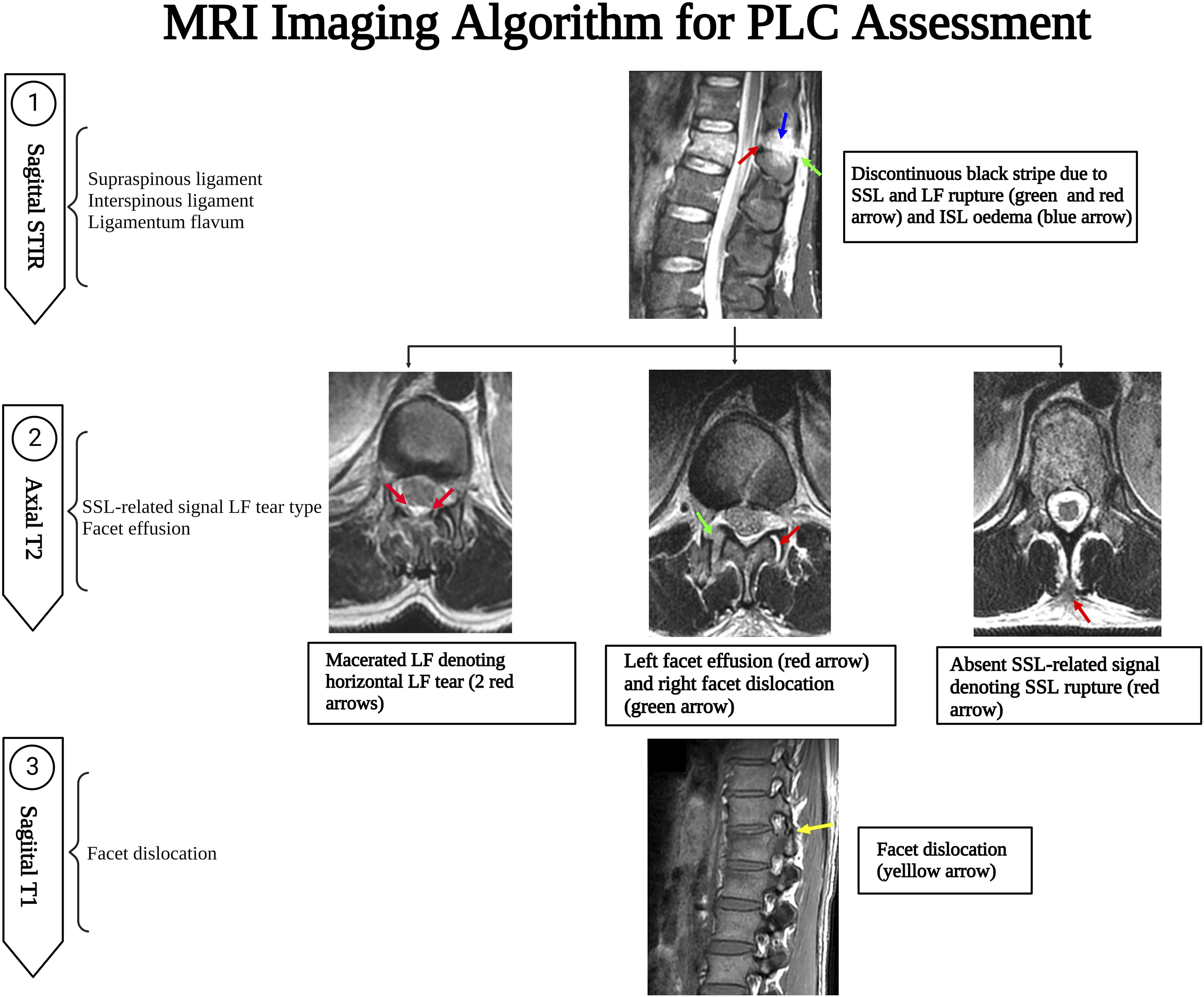
CT Assessment of PLC Injury
A suggested algorithm for MRI PLC assessment is provided in Figure 17. A CT algorithm focuses on the CT findings independently associated with PLC injury and the best plane for detecting them. The midsagittal CT plane is the most useful in screening for VBT, ISW, and SPF. Then a parasagittal plane helps screen laminar fracture and facet misalignment. However, in case of a laminar fracture, coronal reconstruction images are the best to display the fracture line orientation to distinguish VLF from HLF, which is clinically significant.
34
Facet subluxations are the most likely to be overlooked; hence all image planes should be checked for malalignment of any facet articular surfaces. Finally, axial CT may be the most useful to measure FJW because of its orientation.
23
FJW and VLF are the most likely findings to identify PLC injury falsely and, therefore, should be distinguished from HLF and other types of facet malalignment.
12
Computed tomography imaging algorithm for thoracolumbar posterior ligamentous complex assessment.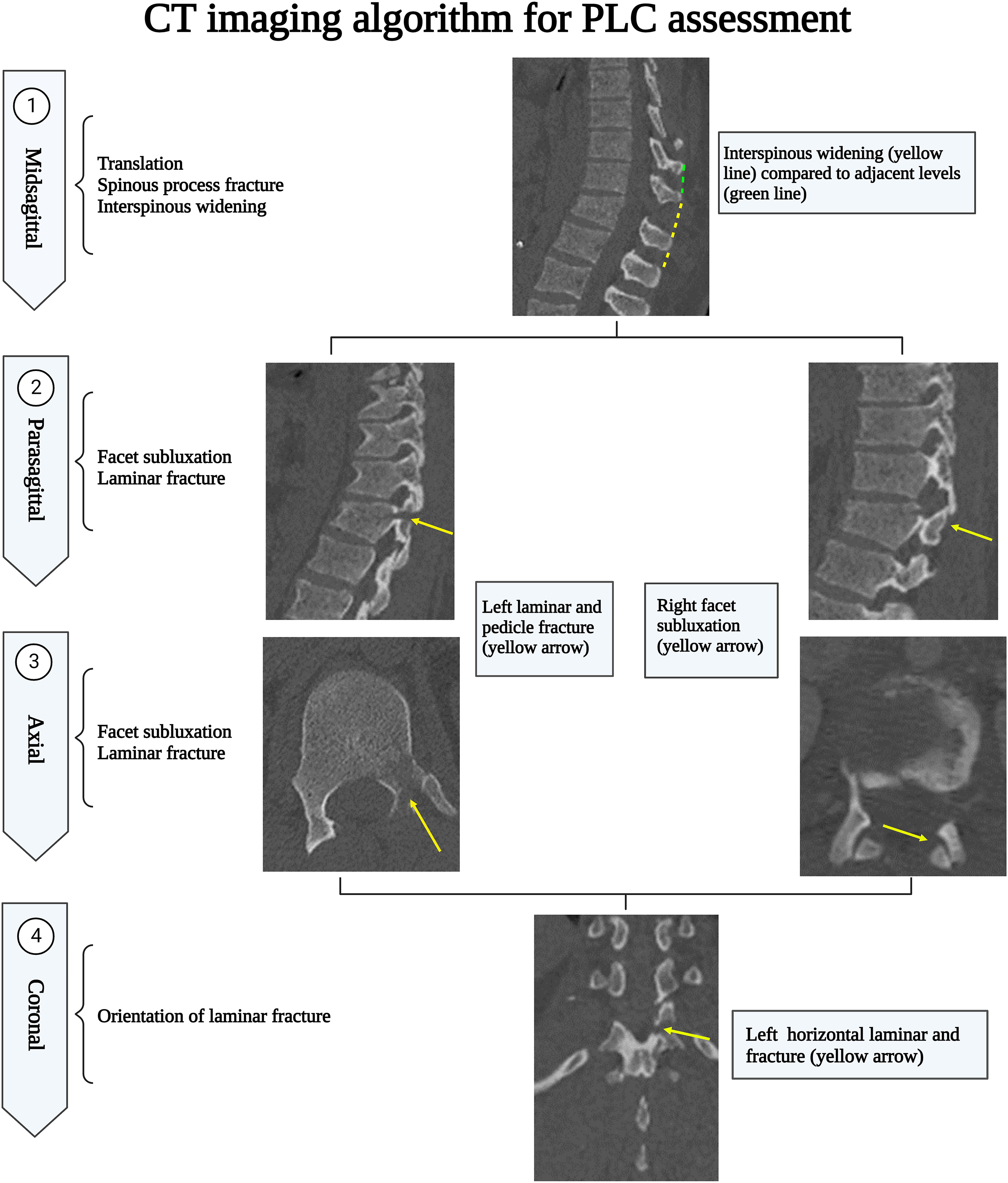
Limitations
The systematic review was limited by data heterogeneity, precluding a meta-analysis from being performed. Another limitation of data heterogeneity is the inconsistent definitions of reference standards because some studies used operative findings to define PLC injury while others used MRI findings or surgeon consensus. Moreover, there is still a need for studies that provide a higher level of evidence to help guide decision-making utilizing available imaging options. While only English articles were included, which may have limited the global generalizability of these studies, there is no evidence of systematic biases due to language restrictions in medical meta-analyses. Finally, the proposed CT and MRI algorithms were developed based on the authors’ own experience. As a result, before being widely implemented in clinical practice, those algorithms should be validated in a multicenter prospective agreement study.
Conclusion
We developed a systematic imaging algorithm for detecting PLC injury in CT and MRI. The pitfalls of image interpretation, as well as pearls for avoiding them, were thoroughly discussed. Furthermore, the predictive value of various CT findings and their morphological variations were discussed based on the available literature. A consensus-based definition of CT findings and a more detailed analysis of their predictive value for PLC injury are required. The implementation of those CT and MRI algorithm will potentially improve the accuracy and reliability of PLC assessment. However, before being widely implemented in clinical practice, those algorithms should be validated in a multicenter prospective reliability study.
Footnotes
Declaration of Conflicting Interests
The author(s) declared no potential conflicts of interest with respect to the research, authorship, and/or publication of this article.
Funding
The author(s) received no financial support for the research, authorship, and/or publication of this article.