
Abstract
Study Design:
Systematic review.
Objectives:
The optoelectronic camera source and data interpolation process serve as the foundation for navigational integrity in robotic-assisted surgical platforms. The current systematic review serves to provide a basis for the numerical disparity observed when comparing the intrinsic accuracy of optoelectronic cameras versus accuracy in the laboratory setting and clinical operative environments.
Methods:
Review of the PubMed and Cochrane Library research databases was performed. The exhaustive literature compilation obtained was then vetted to reduce redundancies and categorized into topics of intrinsic accuracy, registration accuracy, musculoskeletal kinematic platforms, and clinical operative platforms.
Results:
A total of 465 references were vetted and 137 comprise the basis for the current analysis. Regardless of application, the common denominators affecting overall optoelectronic accuracy are intrinsic accuracy, registration accuracy, and application accuracy. Intrinsic accuracy equaled or was less than 0.1 mm translation and 0.1 degrees rotation per fiducial. Controlled laboratory platforms reported 0.1 to 0.5 mm translation and 0.1 to 1.0 degrees rotation per array. Accuracy in robotic-assisted spinal surgery reported 1.5 to 6.0 mm translation and 1.5 to 5.0 degrees rotation when comparing planned to final implant position.
Conclusions:
Navigational integrity and maintenance of fidelity of optoelectronic data is the cornerstone of robotic-assisted spinal surgery. Transitioning from controlled laboratory to clinical operative environments requires an increased number of steps in the optoelectronic kinematic chain and error potential. Diligence in planning, fiducial positioning, system registration and intra-operative workflow have the potential to improve accuracy and decrease disparity between planned and final implant position.
Introduction
The fundamental technological challenge of navigation and robotic-assisted spinal surgery is the virtual world needs to clearly represent the physical, real time world. Among the multiple applications, variables and equipment utilized in navigation and robotic-assisted spinal surgery, the optoelectronic camera source and data interpolation process serves as the foundation for navigational integrity and accuracy, or lack thereof, in the surgical platform. The principles of optoelectronic measurement systems are founded on the basis of devices which have the capability to source, detect and control light and are typically considered a subdivision of photonics. The spectrum of optoelectronic technology platforms are quite diverse, with utilization in sports performance activities such as speed skating and soccer,1-4 human ergonomics,5,6 clinical gait and motion analysis,7-12 musculoskeletal kinematics,13-20 and clinical operative procedures.21-33 To this end, the degree of accuracy and errors acceptable across optoelectronic motion measurement platforms differ considerably based on application. 1 For example, fiducial arrays placed on anatomic pelvic landmarks of alpine skiers reported translation accuracy and errors of 8.37 ± 7.1 millimeters (mm). 34 Although considered adequate for the evaluation of positional or orientation-related differences in this athletic application, discrepancies of this magnitude would be unacceptable in the clinical operative setting. Technological advancements in the accuracy of optoelectronic marker-based systems over the past 20 years have facilitated the adoption and application of these platforms to the field of robotic-assisted spinal surgery.12,35,36 An ensuing plethora of journal publications have documented the safety, efficacy and technical accuracy of navigation and robotic systems,21-24,30-32,37-45 operative surgical applications,25,33,46,47 as well as challenges of process workflow, learning curve and training.28,30,31,39,40
Review of these publications, reveals what could be defined as a significant discrepancy when comparing optoelectronic accuracy in the laboratory setting versus clinical operative environment. An approximate 10-fold decrease in technical accuracy of final implant position (≤2 mm) in the clinical operative environment was observed compared to controlled musculoskeletal kinematic studies (≤0.2 mm), despite utilization of near identical optoelectronic camera systems. Hence, the objective of the current systematic review serves to provide a basis for the numerical disparity that exist when comparing intrinsic accuracy of optoelectronic cameras, accuracy observed in the laboratory setting and accuracy in the clinical operative environment. It is postulated that there exists a greater number of linkages in the optoelectronic kinematic chain when analyzing the clinical operative environment to laboratory setting. This increase in data interpolation, coupled with intraoperative challenges, reduces the degree of accuracy compared to that observed in controlled musculoskeletal kinematic laboratory investigations.
Methods
A comprehensive systematic review of the PubMed and Cochrane Library research databases was performed. The time interval was unrestricted, however, the majority of publications comprising the basis of this analysis ranged from 2000–present. Combinations of key search terms were stratified into the following: optoelectronic measurement systems, technical accuracy, experimental error, robotic assisted spinal surgery, spinal kinematics, and navigation. The search was limited to papers in the English language, indexed in peer-reviewed journals accessible through online searches, and all publications included required a bona fide PubMed identification (pmid) or digital object identifier (doi) citation. The exhaustive literature compilation obtained was then pooled in an EndNote file, vetted to reduce redundancies and categorized into topics pertinent to optoelectronic measurement system accuracy with specific reference to intrinsic accuracy, registration accuracy, musculoskeletal kinematic platforms, and clinical operative platforms. The primary tier for inclusion focused on publications which reported quantitative units of measure (microns, millimeters and degrees) for intrinsic camera accuracy and tolerances, accuracy obtained in a controlled laboratory setting and accuracy in the clinical operative setting. Musculoskeletal kinematic measurement studies were included if motions observed were greater than the standard error of measure (SEM). The second tier of inclusion criteria focused on publications highlighting the applications of optoelectronic measurement systems, percent accuracy of screw placement, inherent inaccuracies of surgical instruments, observational commentary leading to accuracy improvement, and methods to mitigate error potential.
Results
Three-Dimensional Cartesian Rigid Body Transformations
The reported optoelectronic measurements of accuracy, errors and methods to quantify these in the laboratory setting or clinical operative environment are based on a fixed 3-dimensional Cartesian coordinate system of rigid body transformation in millimeters (mm) translation and degrees (deg) rotation along 3 orthogonal axes—X, Y and Z.48-52 This is in accordance to the axial (Y), sagittal (Z) and coronal (X) anatomic planes as defined by Panjabi’s 3-dimensional conceptual framework for spinal kinematics (Figure 1A and B).53-55 From a nomenclature standpoint, accuracy is defined as a combination of trueness and precision according to the published ISO standard 5725-1. 56 Trueness refers to the difference between measured value and true position—typically represented by the mean value of repeated measurements. Precision is a measure of repeatability—typically represented by the standard deviation of repeated measurements and refers to random error and noise within the system. In addition to these standardizations, a useful key measure with regard to accuracy (trueness and precision) is the root mean square distance error (RMS) as given by ei being the 3-dimensional distance error of measurement i and N the number of measurements. 57
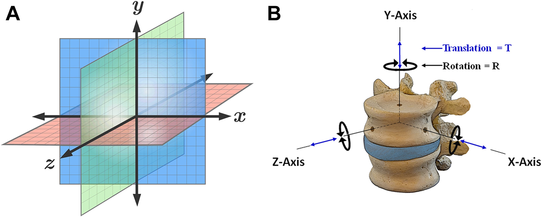
Cartesian coordinate system and conceptual fame for spinal kinematics—schematic representation of a fixed 3-dimensional cartesian coordinate system for calculation of rigid body transformation in millimeters (mm) translation and degrees (deg) rotation along 3 orthogonal axes—X, Y and Z (A). This is in accordance to the axial (Y), sagittal (Z), and coronal (X) anatomic planes as defined by Panjabi’s 3-dimensional conceptual framework for spinal kinematics (B).
Optoelectronic Measurement Systems
Image guided surgery (IGS) is based on the principal of integration and registration of the operative field to pre- or intra-operative data set (e.g. CT or MRI), via amalgamation of an optoelectronic imaging system with robotic platform. 58 Although not necessarily involved in the execution of operative procedures, optoelectronic measurement systems are considered the gold standard in motion capture accuracy1,59 and provide 3-dimensional visualization and guidance; improving task execution, targeting accuracy while functioning in a semi-autonomous fashion. 60 Hence, objective accuracy and error assessments of optoelectronic-robotic interventional platforms is essential. Regardless of optoelectronic camera system, the fundamental triad of common denominators in assessing platform accuracy include: 1) intrinsic accuracy of the source device, 2) registration and tracking accuracy, and 3) application accuracy. Prior to addressing the basis for application accuracy across laboratory versus clinical platforms, the intrinsic and registration accuracy and potential for error propagation are of primary consideration.
Intrinsic (Technical) Accuracy
The initial link in the optoelectronic kinematic chain of data transference resides in the intrinsic accuracy of the camera source. Of the multiple factors affecting downstream optoelectronic accuracy in musculoskeletal kinematic and clinical operative platforms, the intrinsic camera components are most controllable. Mechanical compliance of the system, loose interconnection mechanisms, 58 variation in camera resolution, calibration, imperfect lenses, number of cameras, spatial orientation, noise, computer vision algorithms and jitter all represent sources of intrinsic error in optoelectronic systems.36,58,61-63 Topley and Richards 36 reported that optoelectronic cameras of higher resolution (Vicon 16MP) and number of cameras (n = 12) significantly improve the 3-dimensional spatial accuracy (0.080 ± 0.092 mm) compared to an equal number of cameras of lower resolution (OptiTrack 1.3MP) (0.259 ± 0.084 mm). Khadem et al 64 reported the intrinsic optical tracking error secondary to jitter. In the absence of intrinsic jitter, repeated static measurements from a camera source to fiducial would produce identical kinematic signatures along 3 orthogonal axes. Comparison of 5 different optoelectronic camera systems utilized in image based surgical navigation was performed [Image Guided Technologies (IGS), Boulder, CO and Northern Digital Imaging (NDI), Waterloo Canada]. The intrinsic static jitter (mean and standard deviation values) for the IGS Flashpoint systems ranged from 0.028 ± 0.012 mm (Flashpoint 300 mm), 0.051 ± 0.038 mm (FlashPoint 580 mm) to 0.059 ± 0.047 mm (Flashpoint 1 m). The NDI Polaris systems indicated mean values of 0.058 ± 0.037 mm (active LED) and 0.115 ± 0.075 (passive LED). When performing static single marker measurements according to ASTM guidelines 65 of the NDI Optotrak 3020, a motion analysis system commonly used in musculoskeletal kinematic platforms,13,17 Maletsky et al 66 reported the relative accuracy position between 2 rigid bodies at 0.03 mm translation and 0.04 degrees angulation, respectively. Elfring et al 57 evaluated the static volumetric single marker measurements of 3 commercially available optoelectronic tracking systems utilized in robotic assisted platforms—NDI Polaris P4, NDI Polaris Spectra (active and passive mode) and Stryker Navigation System II (Stryker Inc., Kalamazoo, MI). The Stryker Navigation System II camera and the Polaris Spectra (active mode), exhibited trueness values of 0.058 ± 0.033 mm and 0.089 ± 0.061 mm, respectively. The Polaris Spectra (passive mode) exhibited values of 0.170 ± 0.090 mm, and the Polaris P4 demonstrated the highest static measurement error of 0.272 ± 0.394 mm. As a baseline statement of comparison, the optoelectronic systems utilized in clinical operative or controlled laboratory platforms report only marginal differences in accuracy. Further, the contribution of intrinsic errors is of miniscule value in comparison to error(s) propagation secondary to registration, targeting tracking and application in controlled experimental and clinical operative platforms.
Registration Accuracy and Target Tracking
A second key step in the optoelectronic kinematic chain and highest probable link(s) of error propagation is the registration process. This intra-operative process integrates correlation and mapping algorithms to register the physical patient to the virtual patient via the navigation system, optoelectronic source, fiducial arrays in the operative field, and patient CT images. Accurate, close-to-ideal reference reproducibility of the dataset improves trueness and precision of subsequent intra-operative tracking. Multiple factors affect registration accuracy and target tracking, including optoelectronic camera source, passive versus active arrays, occlusions, distance between fiducial arrays and camera source, and anatomic locations of the coordinate reference fiducials.1,57,67-74
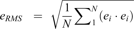
As reported by States and Pappas 75 and Simoes et al, 68 the NDI Certus 3 camera optoelectronic system demonstrated a significantly higher degree of registration target accuracy (0.1 mm translation and 0.13 degrees rotation 75 compared to the NDI Spectra 2 camera system when located 1.5 meters from camera source. 68 The surgical navigation principle of triangulation, necessary to quantify 3-dimensional fiducial array position, is void if 1 of 2 cameras is occluded.61,76,77 Marinetto et al 78 reported tracking errors secondary to camera and fiducial array occlusions when utilizing an 8-camera configuration. Occlusions of a single camera resulted in tracking errors from 0.2 mm to 0.5 mm, while occlusion of 5 cameras resulted in errors from 0.6 mm to 1.6 mm. Optical trackers utilizing multi-camera systems may lead to data redundancy but enables fidelity in data transference, despite fiducial occlusions within the application platform (Figure 2A-C).
Optoelectronic camera sources—comparison of 3 optoelectronic camera systems utilized in motion analysis. The NDI spectra 2 camera system (A), NDI certus optotrak 3 camera system (B), and viconvicon MX13 multiple camera system (C) (Vicon motion systems Ltd., Oxford, UK). The spectra NDI is commonly used in the clinical operative environment and latter 2 systems for musculoskeletal kinematics and biomechanics. The Vicon camera image and testing setup was generously provided by Prof. Dr. Hans Joachim Wilke, PhD, Institute of Orthopaedic Research and Biomechanics, University of Ulm.
The difference between active versus reflective passive markers systems also effect registration accuracy and target tracking. In the case of passive markers, the optoelectronic source floods the operative field and light is reflected back to the sensors via infrared-reflecting spheres. Active markers contain and emit infrared-emitting diodes (IREDs) and provide a more robust signal with increased accuracy compared to passive markers.57,72,79 Furthermore, the distance between optoelectronic camera source and operative field fiducial arrays effect accuracy. 64 Increasing the camera distance from 6 to 8 feet nearly triples the intrinsic registration error along the Z axis (maximum = 0.250 mm) for the Polaris passive fiducial array system. Hence, closer approximation of the optoelectronic camera source to the operative fiducial arrays (≤6 feet or approximately 1800 millimeters) minimizes jitter and improves precision. 64 For comparison, when performing static single marker measurements of the NDI Optotrak 3020 system, the precision in rotation degrades significantly when positioning the camera ≥ 2.5meters from fiducial arrays66,75 (Figure 3A and B).
Active versus passive marker arrays—comparison of active marker arrays used in the laboratory platform as shown attached to the vertebral elements. Note the active markers contain and emit infrared-emitting diodes (IREDs) via the attached wiring configurations (A). In the case of passive fiducial marker arrays (B), the optoelectronic source floods the operative field and light is reflected back to the camera source via infrared-reflecting spheres.
In addition to distance between camera source and fiducial arrays, Citak et al70,80 performed an investigation to determine the maximum acceptable distance between fixed reference arrays and dynamic “mobile” arrays within the operative field. The results demonstrated a mean registration error of 0.04 mm (0.04-0.05 mm) up to a distance of 200 mm from the patient reference array. When mobile fiducial arrays (e.g., end effector) exceeded 200 mm from the reference point, the registration error increased to 0.25 mm (0.24-0.26) (P < .0001). The initial registration and intra-operative working accuracy is significantly reduced with localization of arrays greater than 200 mm from the patient reference point.70,80 Moreover, the magnitude of errors secondary to array obstructions differ based on active versus passive markers and distance between arrays. 35 When comparing 2 active Vicon fiducial arrays versus distance, targeting errors increased from 0.47 mm to 1.2 mm, with corresponding stepwise decreases from 5 cm to 0 cm between arrays. In similarity but of greater magnitude, targeting errors for passive arrays (Qualisys AB, Goteborg Sweden) increased from 0.54 mm to 2.99 mm with decreases from 5 cm to 0 cm between arrays. Hence, as visualized by the camera source, increasing distances between fiducial arrays in the operative clinical setting reduces experimental targeting errors (Figure 4A-D).
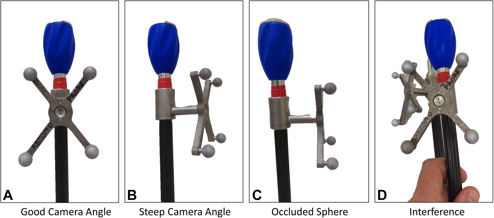
Fiducial array occlusions—Schematic illustration comparing fiducial array configuration and occlusions secondary to optimal optoelectronic camera angle, steep camera angle, occluded sphere and interference between 2 fiducial arrays (A-D).
The effect of transitioning from static to dynamic array localization directly influences accuracy and targeting errors.44,45,69,81 A comparison of static and dynamic motion by Chassat and Lavallee 69 demonstrated a significant increase in array translation error when moving across a spectrum of conditions located 2 meters from the camera source. Using the best-in-class NDI Optotrak 3020 system, the static position error measured 0.28 mm, static position hand held 0.400 mm, and dynamic measure in translation at constant speed 1.29 mm. The magnitude in angular errors was less than translation but still increased significantly through dynamic localization of instrument arrays. 69 These findings were corroborated by Stancic et al 81 with static registration indicated errors of 0.11 mm while dynamic motion of the arrays resulted in errors ranging from 0.250 mm to 1.10 mm with increasing velocities. 81 Hence, higher displacement rates of the operative instrument arrays directly affect the camera’s tracking accuracy.
Two additional clinical factors influencing registration accuracy and targeting errors include the tool to tip distance and accuracy of pre- or intra-operative radiographic CT/MRI data.72,82-84 Static accuracy for a given marker array is on the order of 0.2 mm, however, errors increase significantly when extrapolated to the instrument tip, Wiles et al 72 reported that increasing the distance between fiducial array to instrument tip from 0 to 100 mm decreases static accuracy from 0.4 mm to 0.85 mm, respectively. 72 The array to tool tip distance on instruments utilized in robotic assisted platforms far exceed 100 mm (4 inches). In consideration of the linearity of Wiles et al accuracy degradation with distance calculations, 72 it is postulated that experimental targeting errors of longer instruments are of increased magnitude compared the reported 0.85 mm. Computed tomographic data input affects target accuracy and can be improved with resolutions of 1.0 mm and 2.0 mm versus 3.0 mm slice thickness.82,83
In summary, propagation of computational measurement errors in the optoelectronic kinematic chain has a compounding effect for the following transitions: 1) Measurement of the intrinsic image plane error (IPE) secondary to errors within the optoelectronic system, 2) transitioning from image error to fiducial location error (FLE), and 3) transition from fiducial location error to tracking target error (TRE). The mathematical expressions for these computational transformations are beyond the scope of the current publication but well documented by Fitzpatrick et al71,73 and Sielhorst et al. 61 The margins of error secondary to intrinsic and registration accuracy in optoelectronics are more manageable compared to unpredictable factors related to application in the laboratory versus dynamic clinical intraoperative environments.
Application Accuracy—Musculoskeletal Kinematics Laboratory Platform
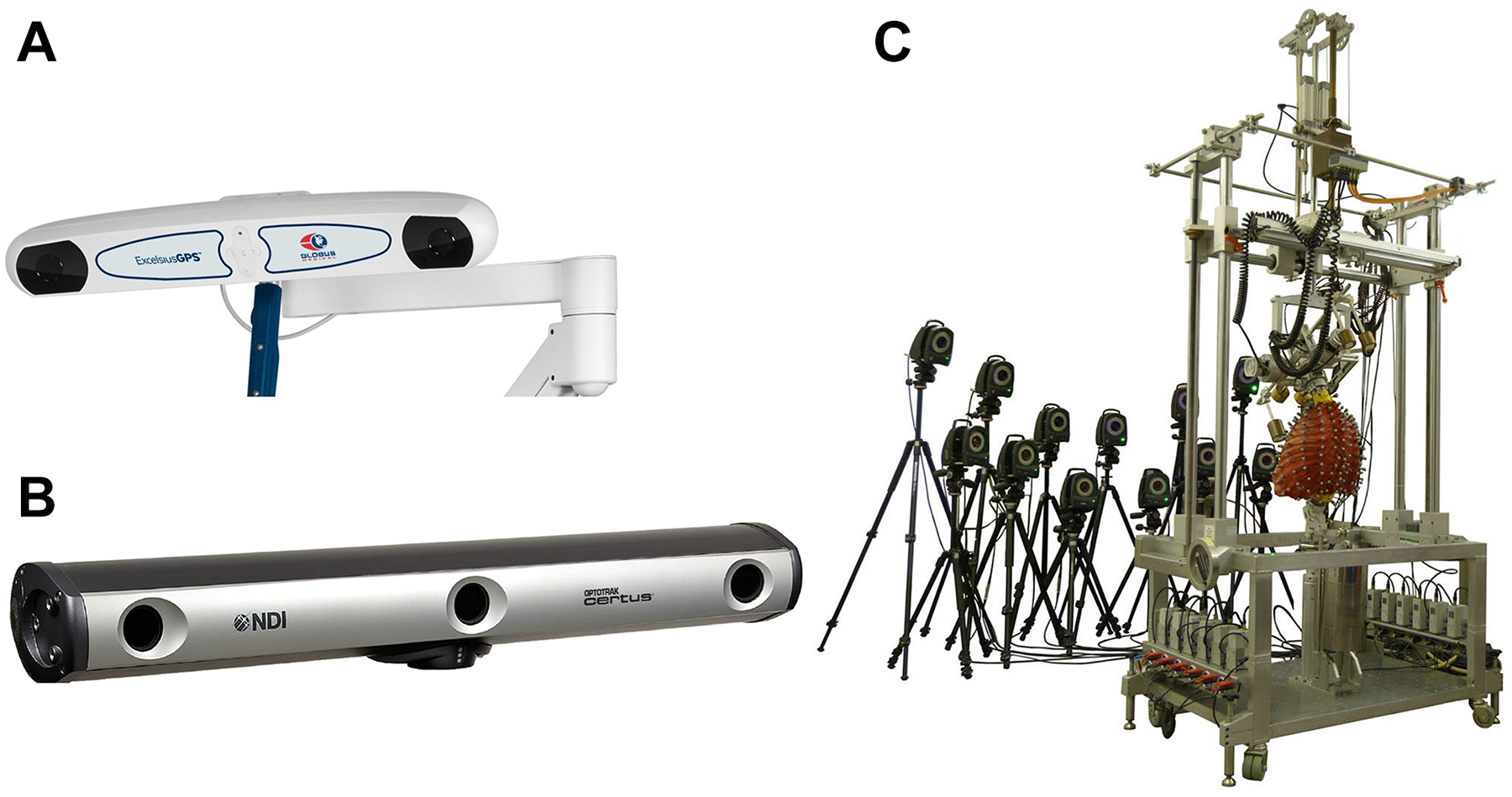
Over the last 30 years, a plethora of spine publications have documented the biomechanical properties of the occipitocervical through lumbopelvic spine under controlled laboratory conditions utilizing Panjabi’s 3-dimensional conceptual framework for testing.17,53-55,85 In contrast to the challenges of the clinical operative environment, motion analysis of spinal implant and anatomic vertebral structures(s) in the controlled laboratory setting is performed utilizing a 6 degree of freedom musculoskeletal simulator interfaced with an optoelectronic measurement system. The fundamental principles pertinent to maximizing optoelectronic accuracy include mounting the specimen to a rigid testing platform, affixing active or passive fiducial arrays directly to implants or anatomic structures using screw-bolt fixation, and creating rigid body configurations parallel to the camera source. Multidirectional flexibility testing is typically performed along 3 predominant loading axes—flexion-extension, lateral bending, and axial rotation under controlled displacement rates of 1 to 3 degrees per second for multiple cycles. To this end, a series of laboratory investigations using the NDI Certus and Vicon MX13 camera systems (Vicon Motion Systems Ltd., Oxford, UK) reported the peak limits of optoelectronic accuracy when evaluating kinematics of the osteoligamentous spine13-19,86-92 (Figure 5A and B).
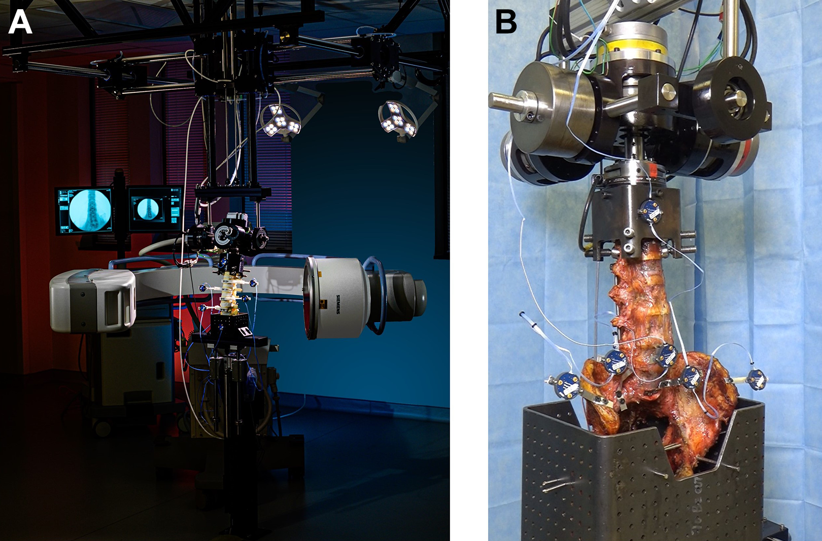
Application accuracy—musculoskeletal kinematics laboratory platform in contrast to the challenges of the clinical operative environment, motion analysis of spinal implant and anatomic vertebral structures(s) in the controlled laboratory setting is performed utilizing a 6 degree of freedom musculoskeletal simulator interfaced with an optoelectronic measurement system (A). The fundamental principles pertinent to maximizing optoelectronic accuracy include mounting the specimen to a rigid testing platform, affixing active or passive fiducial arrays directly to implants or anatomic structures using screw-bolt fixation, and creating rigid body configurations parallel to the camera source (B).
Cunningham et al 14 compared occipital plate versus intracranial anchors for reconstruction of the occipitocervical (O-C) junction. The reported differences (degrees) in axial rotation at the O-C junction based on optoelectronic measurements were 4.13 ± 2.05 (intact), 0.22 ± 0.13 (plate) and 0.30 ± 0.21 (anchor). Rotation of the plate and anchor, with respect to the occiput, in flexion-extension ranged from 0.06 ± 0.05 to 0.10 ± 0.08, respectively. Although not of clinical significance, the study quantified differences on the order of 0.1 degree between 2 methods of occipitocervical fixation. Bowden et al 86 described the variability in “quality of motion” of L4 relative to the L5 vertebral elements, following various methods of vertical preload. The optoelectronic data quantified differences in L4 anteroposterior translations of 0.6 mm and rotations of 0.6 degrees between different testing conditions. Ilharreborde et al 87 reported dynamic kinematic evaluation of the multi-segmental lumbar spine under dynamic loading conditions indicated peak accuracy to within 1.10 ± 0.18 degrees (L2-L3) and corresponding translations of 0.48 ± 0.06 mm rotation (L3-L4) with application of 7.5 Nm pure moment load. In a complex kinematic study utilizing a Vicon optoelectronic system, La Barbera et al18,19 investigated lumbar interbody cages with Ponte osteotomy versus pedicle subtraction osteotomy for severe sagittal imbalance, the peak accuracy of neutral zone measurements (degrees) across the intact L3-L5 segments demonstrated values of 0.7 (Range 0.3-1.9) in flexion-extension, 1.0 (Range 0.1-3.8) in lateral bending and 0.2 (Range 0.1-0.9) in axial rotation in flexion-extension.
From a kinematic standpoint, the sacroiliac junction (SIJ) presents formidable challenge to definitive and accurate measurement using optoelectronics—reaching the 0.1 degree accuracy error measurement limitations of most optoelectronic systems.18,19 Jeong et al 88 was able to differentiate the range of motion (degrees) of the SIJ in lateral bending when comparing the intact condition (1.5 ± 1.5), unilateral fusion (1.4 ± 1.6) and bilateral fusion (1.1 ± 1.0). Despite quantification of SIJ motion within a range of 0.5 degrees of accuracy, the comparisons were not significant. Osterhoff et al 89 quantified the effects of cement augmentation on sacroiliac screw position and fracture site motion using NDI optoelectronics. Screw tip positioning within the sacrum was quantified to an accuracy level of 0.7 mm (Range 0.5-1.3), with a corresponding vertical (Y axis) SIJ range of motion of 1.2 mm (Range 0.6-1.9) under cyclic compressive loads. In a comprehensive S2 alar iliac screw instrumentation study using 21 lumbopelvic specimens, Cunningham and co-workers 13 reported SIJ motion (degrees) to accuracies of 1.78 ± 0.96 (flexion-extension), 0.52 ± 0.34 (lateral bending) and 0.48 ± 0.32 degrees (axial rotation). In a similar study by Dall et al 15 evaluating SIJ fusion using lateral sacroiliac screws, optoelectronic tracking quantified the intact SIJ motion (degrees) under flexion-extension, lateral bending and axial rotation at 1.80 ± 1.62, 0.44 ± 0.35 and 1.13 ± 0.82, respectively. Additional studies on intact SIJ kinematics reported translations along the 3-dimensional coordinate axes on the order of 0.1 mm to 1.04 mm with corresponding rotations of 0.11 to 1.14 degrees.16,91,92
Laboratory workflow methods and conditions for experimental musculoskeletal kinematic studies are streamlined and optimized for maximizing optoelectronic accuracy. Factors of specimen stabilization, alignment, camera resolution, proximity to fiducials, planar visualization of the active arrays, and controlled motion application account for the high degree of accuracy reported in these studies. Moreover, in difference to the operative clinical environments, non-destructive testing procedures can be repeated multiple times on the same specimen to improve data accuracy. The collective effect of testing methodology and limited experimental coordinate transformations between data input/output reduces error propagation and maximizes optoelectronic accuracy (Figure 6).
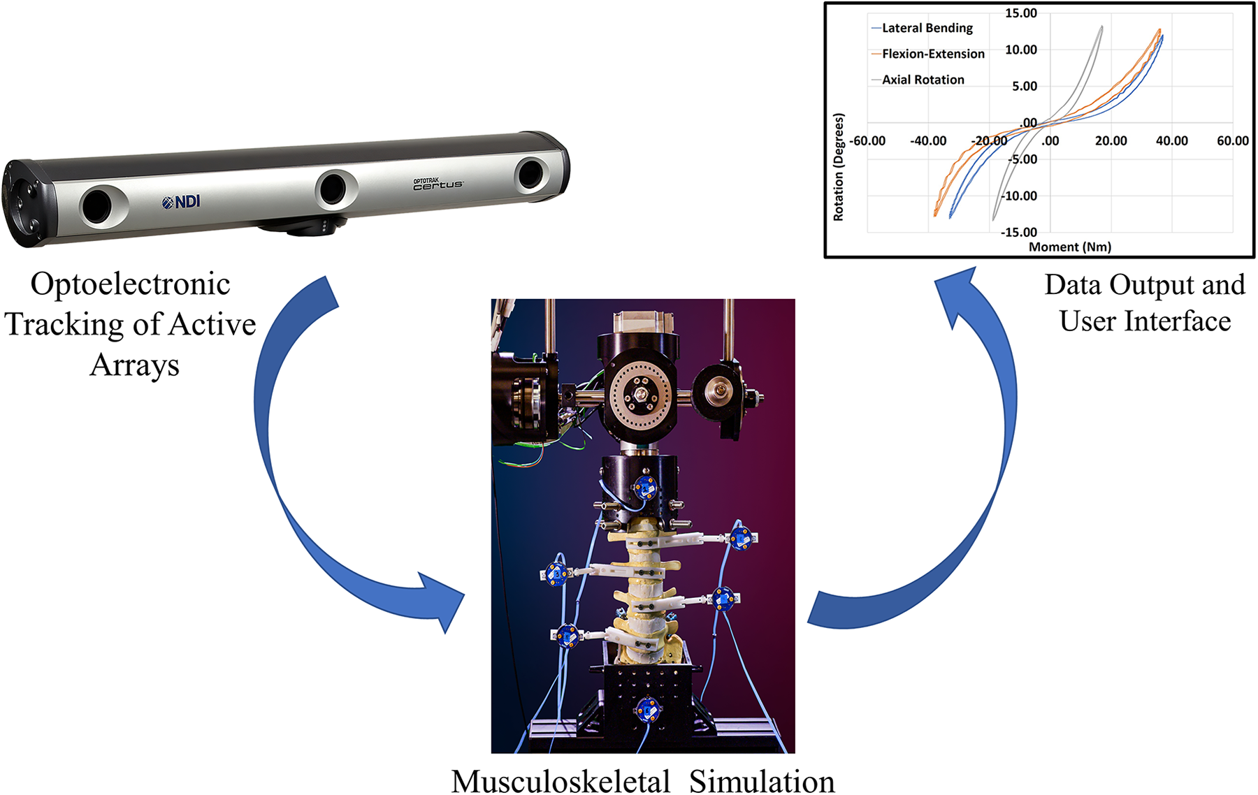
Laboratory platform for optoelectronic data transference process—Schematic illustration demonstrating the laboratory workflow and process for data transference utilizing optoelectronic tracking. The camera source visualizes the active fiducial arrays affixed to the vertebral elements and transfers the data directly to the user interface for computational analysis. The collective effect of testing methodology and limited experimental coordinate transformations between data input/output reduces error propagation and maximizes optoelectronic accuracy.
Application Accuracy—Clinical Operative Platform
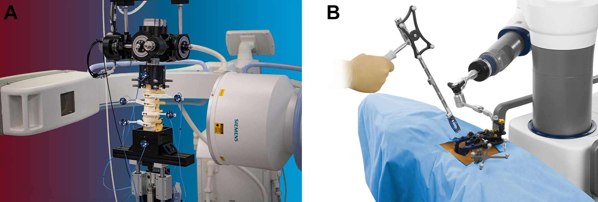
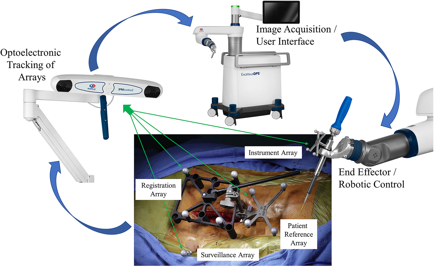
Transitioning from controlled laboratory conditions to the dynamic variability of a clinical operative environment presents a different set of application challenges for maintaining peak optoelectronic accuracy. Unique to robotic assisted spinal surgery and in difference to the laboratory setting, the intra-operative process requires considerably more steps in the transference of optoelectronic kinematic data. This complex process flow integrates correlation and mapping algorithms to register the physical patient to the virtual patient via the navigation system, optoelectronic source, surveillance markers, patient reference markers, end effector instruments in the operative field, and patient CT images. Accurate, close-to-ideal reference reproducibility and maintenance of this dataset is the primary intra-operative objective and challenge (Figure 7).
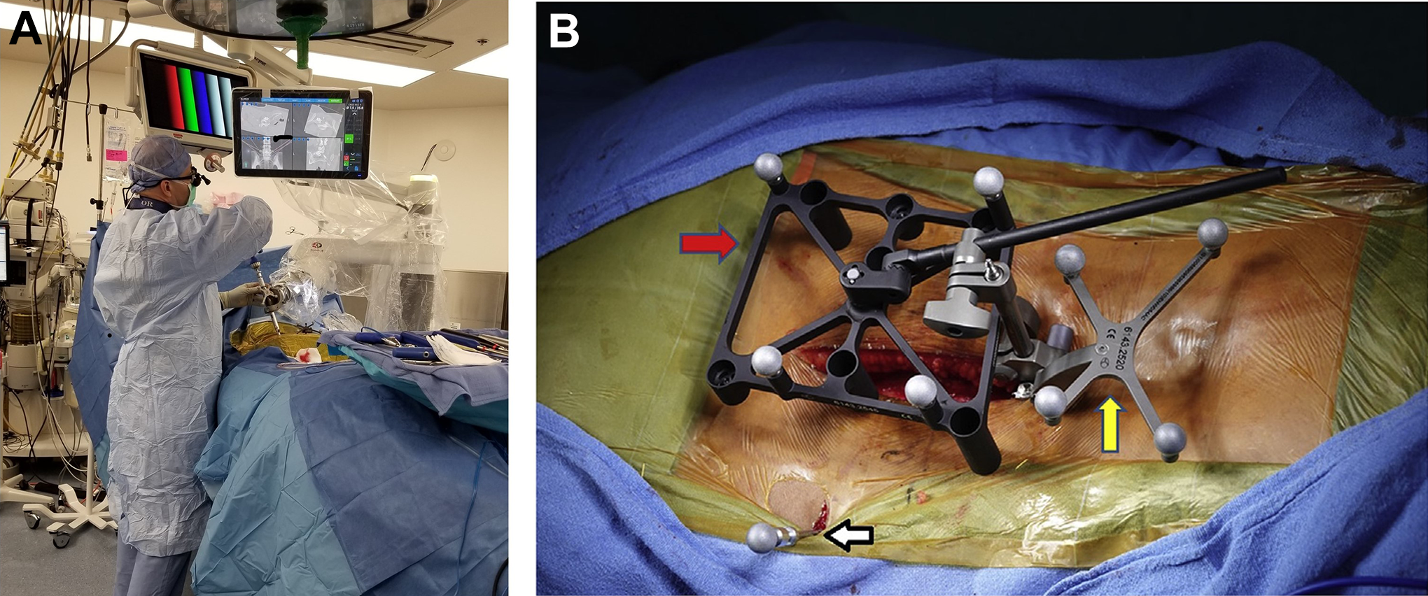
Application accuracy—clinical operative platform. Intra-operative images highlight the transition from controlled laboratory conditions to the dynamic variability of the clinical operative environment (A). A different set of application challenges are required for maintaining peak optoelectronic accuracy related to registering the physical patient to the virtual patient via the navigation system, optoelectronic source, surveillance markers, patient reference markers, end effector instruments in the operative field and workflow. The intra-operative images were generously provided by the operative surgeons, (A) Dr. Vladimir Sinkov, MD and (B) Dr. Bhavuk Garg, MD.
Despite utilization of near identical optoelectronic sources and fiducial arrays, a consistent disparity exists when comparing the reported technical accuracies in the laboratory setting versus clinical operative environment. An approximate 10-fold decrease in accuracy was observed when comparing the final implant position (≤2 mm) in the clinical operative environment to musculoskeletal kinematic studies (≤0.2 mm). An extensive number of peer reviewed journal publications have documented the use, efficacy safety and technical accuracy achieved with robotic-assisted spinal surgery.23,28,30,37,39-41,44-46,93-123 The focus in reviewing these publications was to highlight the technical accuracy observations and determine a basis for discrepancy between planned versus actual final implant position based on postoperative CT images. In case studies where quantitative measurements were not reported, the Gertzbein and Robbins 124 score (GRS) was adopted to calculate pedicle screw implant position. According to the GRS classification, screws centered within the pedicle are considered grade A; < 2 mm from center is a grade B; a breach from 2 mm to 4 mm is grade C; a breach from 4 mm to 6 mm is grade D; and > 6 mm is grade E. Grades of A and B (< 2 mm pedicle breach) are considered clinically acceptable, and all other grades indicate malposition.
Helm et al 94 performed a comprehensive literature review on the technical accuracy of 12 622 pedicle screws implanted using a variety of image guided surgery navigation systems. As reported, 11 830 were positioned perfectly according to pre-operative plan (A), 395 screws within less than 2 mm of plan (B), 92 breached between 2 mm to 4 mm off center (C), and 55 were within 4 mm to 6 mm of the pre-operative plan. The balance of 250 screws remained ungraded due to radiographic issues. Zhang et al 45 reported one of the largest compilations assessing screw accuracy in robotic assisted spinal surgery. A total of 23 studies including prospective, prospective randomized control trials and retrospective reviews comprised the basis of this publication with a total of 5,013 pedicle screw positions evaluated. The accuracy according to GRS grades of A and B (less than 2 mm cortical breach) was 4,781 screws (95.38%), while the balance of 232 screws (4.61%) ranged from 2 mm to 6 mm when comparing the planned to actual final positions. Solomiichuk et al 41 reported on 192 screws implanted in 35 patients. Trajectories were Grade A or B (less than 2 mm) in 162 (84.4%) of screws. The malposition rate of 2 mm to 6 mm was present in 30 of 192 screws (15.6%) with 23 of these occurring in the thoracic spine, where pedicle widths are significantly less than the lumbar region.103 125 Devito et al 93 reported on the technical accuracy placement of 646 pedicle screws inserted in 139 patients using postoperative CT scans. 577 were centered in the pedicle, 58 were less than 2 mm off center, 9 breached 2 mm to 4 mm off center and 2 screws deviated greater than 4 mm from the pedicle wall. Schatlo et al 39 reported on the technical accuracy of 244 lumbar pedicle screws. 204 screws (83.6%) were graded as a perfect trajectory (A) compared to the pre-operative plan, 19 (7.8%) were less than 2 mm (B), 9 (3.7%) breached 2 mm to 4 mm off center (C), 4 (1.6%) breached from 4 mm to 6 mm (D), 2 (0.8%) were greater than 6 mm off center and 6 (2.5%) screws required revision.
A comprehensive study from Keric et al 107 reviewed the technical accuracy of 1857 screw positions based on postoperative CT scans. Of the 1857 screws, 1799 (96.9%) were graded as acceptable or good position, 38 screws (2%) exhibited deviations from 3 mm to 6 mm and 20 screws (1.1%) were greater than 6 mm from the planned trajectory. The 58 malpositioned screws (3 mm to 6 mm deviations) were located primarily in the upper and lower thoracic regions versus the lumbar spine. These deviations were considered secondary to smaller pedicle morphometry 126 and instrument skiving. 107
In consideration of the range for “acceptable” deviations (best case = <2 mm) between planned and actual positions in the clinical setting, attention must be directed toward the anatomical pedicle morphology from the cervical to lumbar regions. For typical cervical vertebrae (C3 to C6) the mean pedicle width was reported 4.9 ± 0.9 mm.127,128 In the thoracic region, pedicle width progressively decreases from T1 to T5 (mean 3.65 ± 0.40 mm) and increases from T6 though the T12 levels (mean 7.89 ± 0.70 mm).103,125 The lumbar vertebrae allow greater cross sectional areas for “ideal” pedicle screw placement, however, the proximity of adjacent exiting nerve roots ranges from 2.9 mm to 6.2 mm proximally and 0.8 mm to 2.8 mm distally. Moreover, the distance between the medial borders of pedicle to thecal sac ranges from 0.9 mm to 2.1 mm. 129
Basis for Disparity in Optoelectronic Accuracy
A key consideration pertaining to optoelectronic accuracy in the clinical environment compared to the laboratory setting is the dynamic nature of the operating room. The basis for disparity in accuracy when equating the laboratory versus clinical operative platforms is a result of the combined, cumulative errors secondary to the intraoperative workflow process, variability in anatomic morphology, and spinal flexibility. Of fundamental importance, and the crux of the matter, related to error propagation in navigation and robotic-assisted spinal surgery is the assumption that the workflow platform and patient’s spine is rigid, and as such, motion of any type is perceived as a rigid body transformation. Optoelectronic error reduction in the clinical flow requires stabilization of the camera source, rigid fixation of surveillance arrays in the iliac crest, stable attachment of patient reference and registration arrays to anatomic landmarks, and end effector instruments arrays which are inflexible. The end effector is the last link where the robotic enters the workspace and small rotations or translations in the array references can lead to large errors in instrument position. Although accurate, close-to-ideal reference reproducibility of these steps will reduce errors, the reality is that fixed arrays do move—leading to increased relative motions between arrays and subsequent error propagation and disparity between the physical, real time world and virtual world. Moreover, spatial errors can be further magnified due to geometrical distortion of preoperative images, and tracking error of the surgical instruments. 130 To register the physical patient to the virtual patient, Grunert et al 67 proposed a series of transformation matrices, including fiducial-based paired-point transformation, surface contour matching, and hybrid transformation. The hybrid transformation process is most applicable to robotic assisted spinal surgery as it includes the methods of surface-based and pair-point based methods with implanted fiducials. As such, tracing at least 3 anatomic landmarks with navigational confirmation serves to reduce error potential.
Several publications on optimizing clinical workflow process have been reported31,38,42,76 130-133 Lieberman et al 31 provides an excellent description of the step-by-step workflow process in robotic assisted spinal surgery. The report provides a concise methodological approach to operative workflow, while at the same time providing a collective basis for potential error(s) propagation in the clinical setting. The sequential description of process flow/error potentials includes pre-operative and intra-operative registration, dislodgement of reference arrays, damaged or bent navigation tools134-136 and arrays occlusions (e.g., distance and blood), skiving or tool deflection secondary to sloped anatomic topology or muscle retraction, and untracked patient movement during the spinal destabilizing procedure. In addition to unintended motion or bending of fiducial arrays, the inherent differences in anatomic topology, bone mineral density and flexibility of the patient’s spine, both before and following destabilization and reconstruction procedures, cannot be overemphasized. The challenge is the spine is often flexible—the drill and robotic arm may be properly located, but highly mobile, multi-segmental spinal reconstructions with minimal deflection force leads to unintended rotation or translation of the operative vertebral elements, skiving or tool deflection, and effects precision rate during screw insertion.31,38 132 133 135 137 The basis for decreased technical accuracy in the clinical operative platforms is a result of combined, cumulative errors secondary to the intraoperative workflow process, number of kinematic linkages and variability in patient spinal morphology and flexibility (Figure 8).
Clinical platform for optoelectronic data transference process. Schematic illustration demonstrating the operative clinical workflow and process for data transference utilizing optoelectronic tracking. Unique to robotic assisted spinal surgery and in difference to the laboratory setting, the intra-operative process requires considerably more steps in the transference of optoelectronic kinematic data. This complex workflow process integrates correlation and mapping algorithms to register the physical patient to the virtual patient via the navigation system, optoelectronic source, surveillance markers, patient reference markers, end effector instruments in the operative field, and patient CT images. Accurate, close-to-ideal reference reproducibility and maintenance of this dataset is the primary intra-operative objective and challenge.
Discussion
In reviewing the intrinsic technical accuracy and registration accuracy, there exists a substantial burden of proof that the potential performance in optoelectronics is nearly identical between the 2 platforms—laboratory versus clinical operative—under static conditions. The downstream difference in optoelectronic technical accuracy and disparity between the 2 platforms is secondary to the dynamic factors unique to each. The laboratory workflow methods and array registration for experimental musculoskeletal kinematic studies are rigid, highly controlled, with limited experimental coordinate transformations between data input/output—reducing error propagation and maximizing optoelectronic accuracy. Unique to robotic-assisted spinal surgery and in difference to the laboratory setting, the dynamic intra-operative process necessitates considerably more steps in the transference of optoelectronic kinematic data. The complex data flow process integrates correlation and mapping algorithms to register the physical patient to the virtual patient via the navigation system, optoelectronic source, surveillance markers, patient reference markers, end effector instruments, and patient CT images. Essentially, this is a comparison of technical accuracy between a rigid, highly controlled setting and a variable environment with multiple data input factors. The collective effect results in an increased potential for error propagation from experimental coordinate transformations, data processing and optoelectronic kinematic linkages in the clinical setting.
Although workflow and patient related factors provide a basis for decreased accuracy in the clinical setting, with differences between planned versus actual final implant position ranging from 1.5 mm to 3 mm, it could be argued with some degree of confidence that these technical inaccuracies are inconsequential and of no clinical significance in anatomic zones permitting such deviation (e.g., L5 pedicle). However, in cases of cervical or thoracic operative procedures with pedicular dimensions less than 3.5 mm diameter and neural structures within 0.8 mm proximity to pedicular cortices, technical errors of 2 mm to 3 mm are significant, and navigational integrity and reliability of the data transformation process are of paramount importance. With this level of technical inaccuracy, there is basis for contraindication in the use of navigation and robotic-assisted spinal surgery depending on the indications presented and extent of confounding factors that may decrease registration accuracy and subsequent technical accuracy of implant placement.
The fundamental technological challenge of navigation and robotic-assisted spinal surgery is the virtual world needs to clearly represent the physical, real time world. Navigational integrity and maintenance of fidelity in the transference of optoelectronic data is the cornerstone of robotic-assisted spinal surgery. Transitioning from the controlled laboratory setting to clinical operative environment requires an increased number of steps in the optoelectronic kinematic chain and potential for error propagation in experimental coordinate transformations. Moreover, intra-operative challenges of array location, system registration, spinal flexibility, anatomic topography and workflow affect navigational integrity and provide a basis for the disparity of optoelectronic accuracy in the clinical environment compared to the controlled laboratory setting. A continuum of decreased accuracy is demonstrated when comparing the optoelectronic camera source itself to application in musculoskeletal platforms, and finally, clinical operative environment. Diligence in the areas of pre-operative planning, source camera and fiducial positioning, system registration and intra-operative process workflow have the potential to improve accuracy and decrease disparity between planned and final implant position.
Footnotes
Acknowledgments
The authors would like to credit Mir Hussain, Nobert Johnson (Globus Medical Corporation), and Dr. Vladimir Sinkov, MD, for their expertise and objective comments in the preparation of this manuscript.
Declaration of Conflicting Interests
The author(s) declared no potential conflicts of interest with respect to the research, authorship, and/or publication of this article.
Funding
The author(s) received no financial support for the research, authorship, and/or publication of this article.