
Abstract
Study Design:
A novel technique for S2-alar-iliac (S2AI) screw placement was analyzed.
Objectives:
Accurate confirmation of the S2AI screw trajectory with free-hand techniques is not simple, although some anatomical landmarks have been reported. To overcome the drawback, we aimed to introduce our technique for S2AI screw placement assisted with a guidewire using a new anatomical landmark.
Methods:
A total of 104 S2AI screws of 52 patients who underwent S2AI screw placement were investigated. Navigation software was used to simulate S2AI screw placement preoperatively. Screw placement was performed with the nonfluoroscopic free-hand technique. In this technique, a guidewire is inserted into the ilium from the extra-articular portion of the sacroiliac joint just lateral to the ideal screw entry point toward the tip of the greater trochanter and guides the screw trajectory. If the direction of the guidewire is satisfactory, all procedures of screw insertion are performed accordingly. The screw accuracy was assessed with computed tomography.
Results:
The modal size of the screw was 9.5 mm × 90 mm. The average horizontal angle was 42.0° (SD = 5.1°) on the right and 40.7° (SD = 4.7°) on the left. Of the 104 screws, 4 screws (3.9%) breached dorsally. No screw-related complication was observed.
Conclusions:
Because the guidewire can be inserted at an angle according to the individual morphology of the sacroiliac joint, it will be a reliable guide for the screw trajectory. This technique with a guidewire would help improve the accuracy of S2AI screw placement.
Keywords
Introduction
S2-alar-iliac (S2AI) screw placement is an essential technique for various spinal diseases that require long segment fixation extending to the sacrum. 1,2 Various techniques of S2AI screw placement have been reported, such as free-hand techniques, C-arm fluoroscopic guidance, surgical navigation, and robotic guidance. 3 -6 Screw insertion under surgical navigation or robotic guidance is useful, but such equipment is not available in every hospital. Therefore, S2AI screws are inserted mostly using free-hand techniques or C-arm fluoroscopy.
Determination of the screw entry point and screw trajectory is crucial for free-hand techniques. There is less controversy about anatomical landmarks of the screw entry point and screw angle in the caudal direction: typically, the screw entry point is located just lateral to the midpoint between the S1 and S2 dorsal foramina, and the landmark of the screw angle in the caudal direction is the tip of the greater trochanter. However, to our best knowledge, no article has mentioned reliable signposts or anatomical landmarks of the screw angle in the ventral direction. Available data on screw angles in the coronal and sagittal planes was obtained from computed tomography (CT)-based measurements. Therefore, confirming the screw angle in the ventral direction in the operative field is not simple. Even though the S2AI screw is inserted with a free-hand technique, C-arm fluoroscopy may be needed to check for screw breach in the caudal and ventral directions.
Given individual differences in the morphology of the sacroiliac joint, there is a need for a reliable guide for the screw trajectory in the operative field. Thus, to improve the accuracy of screw placement, we aimed to introduce our technique for S2AI screw placement assisted with a guidewire using a new anatomical landmark.
Materials and Methods
Medical records of all 52 consecutive patients with various thoracolumbar diseases who underwent spinopelvic fixation with S2AI screws from October 2014 to March 2019 were reviewed. All patients during this period were included. Navigation software (iPlan Spine version 3.0.6; Brainlab, Munich, Germany) was used preoperatively to determine the ideal entry point and S2AI screw trajectory. The lumbosacral transitional vertebra was identified by 3-dimensional CT images and were classified according to the Castellvi classification 7 : type I, unilateral (Ia) or bilateral (Ib) dysplastic transverse processes greater than 19 mm; type II, incomplete unilateral (IIa) or bilateral (IIb) lumbarization/sacralization; type III, complete unilateral (IIIa) or bilateral (IIIb) lumbarization/sacralization; and type IV, mixed. This study was approved by the institutional review board at the Yokohama Minami Kyosai Hospital.
Surgical Technique
The entry point was usually the lateral sacral crest located between the S1 and S2 dorsal foramina; occasionally, it was the caudal and lateral edge of the S1 foramen. The tip of the greater trochanter was used as a landmark of the S2AI screw angle in the caudal direction (Figures 1A-1D).
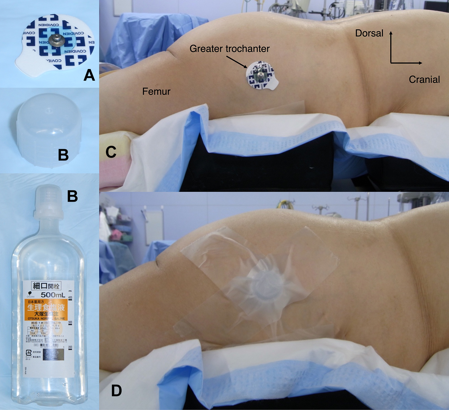
To easily identify the tip of the greater trochanter from the body surface during screw insertion, an electrocardiogram electrode was attached (A) thereon; a plastic bottle cap was placed (B) on the electrode and secured with medical tape (C and D).
Because checking the appropriate screw angle in the ventral direction is particularly difficult with free-hand techniques, we used a 3-mm stainless-steel guidewire 10 cm in length (Itoika, Tokyo, Japan) as a guide for the screw angle in the ventral direction. The guidewire was inserted from the extra-articular portion of the sacroiliac joint just lateral to the ideal entry point toward the tip of the greater trochanter between the sacral and pelvic tuberosities.
Then, the guidewire was hammered into the ilium until it stabilized (usually approximately 5 cm in depth; Figures 2A-2E). After placing the guidewire, we took 1-shot pelvic inlet and lateral pelvic X-ray images to confirm the direction of the guidewire (Figures 3A-3D). If the direction was satisfactory, all procedures of screw insertion were performed along the guidewire.
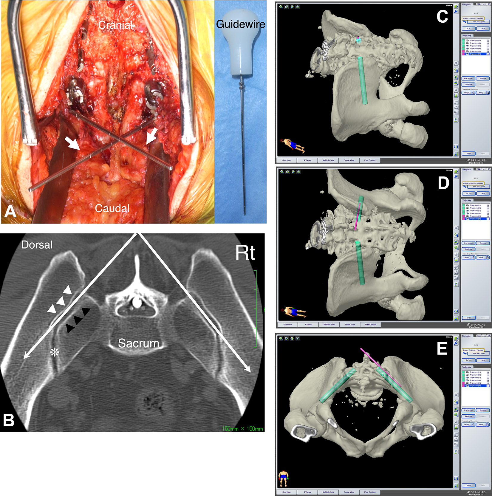
A. Intraoperative photo demonstrating the guidewires (white arrow). B. Axial computed tomography image at the level between the S1 and S2 posterior foramina, which is sliced parallel to the S1 endplate. The guidewire (white long arrow) appears to be easily introduced to the ilium if it is inserted along the sacral tuberosity from the extra-articular portion of the sacroiliac joint just lateral to the ideal entry point of the S2-alar-iliac screw—between the sacral (black arrow head) and iliac (white arrow head) tuberosities. The S2-alar-iliac screw is inserted properly if it penetrates the articular portion of the sacroiliac joint (asterisk) along the guidewire. C-E. These images are created by the navigation software. The light green represents the S2-alar-iliac screw, and the pink represents the guidewire, which is inserted along the sacral tuberosity from the extra-articular portion of the sacroiliac joint.
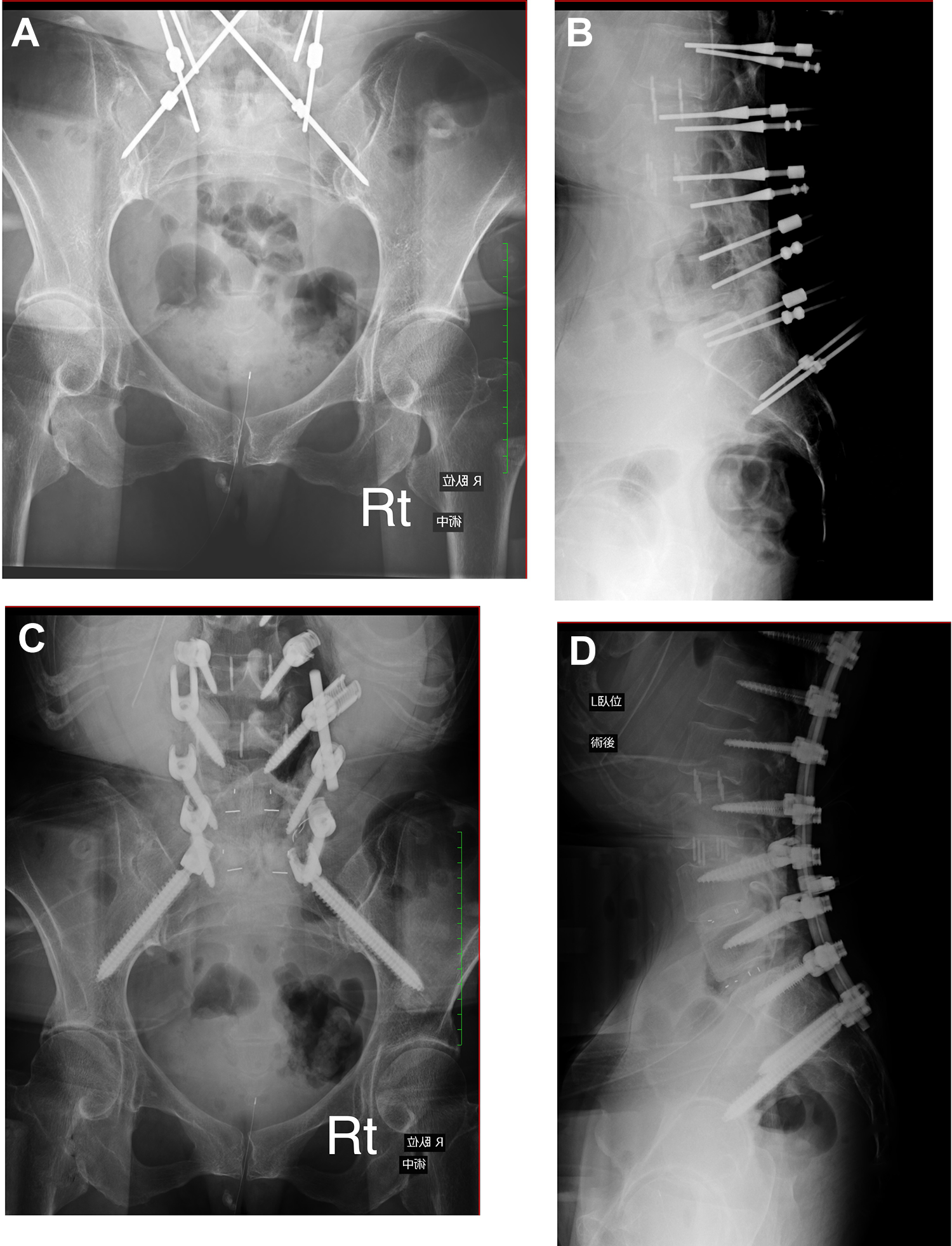
Intraoperative pelvic inlet and lateral pelvic X-ray images. A and B. After inserting the guidewires. C and D. After inserting the screws. The right guidewire is in place, but the left guidewire is somewhat away from the greater sciatic notch. The left S2-alar-iliac screw should be inserted slightly caudal to the guidewire.
The screw insertion technique was almost the same as previously reported. 5,8 A 4-mm high-speed diamond burr was used to make a cortical breach at the screw entry point. Then, a straight sharp-tipped pedicle probe was advanced toward the sacroiliac joint along the guidewire. After piercing the sacroiliac joint (usually 5 cm in depth) with the pedicle probe, a ball-tipped sounder was used to confirm whether the tip was within the ilium. If no iliac cortical bone was breached, the probe was advanced further until the iliac cortical bone was reached, usually 7 to 9 cm in depth. The S2AI screw trajectory was usually undertapped by 1 mm smaller than the target screw diameter. Then, the S2AI screw length was measured and the screw was inserted.
S2AI Screw Analysis
Analysis of the S2AI screw position was performed with postoperative CT. The horizontal screw angle (angle in the ventral direction) was measured using a line connecting each posterior superior iliac spine as a reference in axial CT images. The direction of a screw breach was divided into the ventral, dorsal, and caudal directions. Ventral and dorsal breaches were explored in axial images, and a caudal breach was explored on the coronal images. The descriptive statistics were expressed as means and SD values.
Results
Demographic Data
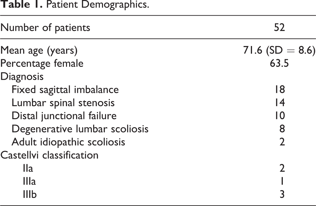
A total of 104 S2AI screws inserted in 52 patients were analyzed. Every patient had 1 screw inserted bilaterally. No patient in this series had spinal deformities with pelvic and sacral dysplasia, but the lumbosacral transitional vertebra was detected in 6 patients (11.5%). Patient demographics are summarized in Table 1.
Patient Demographics.
Screw Analysis
S2AI screw analysis is shown in Table 2. The modal size of the screw was 9.5 mm in diameter and 90 mm in length. The average horizontal angle was 42.0° (SD = 5.1°) on the right and 40.7° (SD = 4.7°) on the left, which were comparable to the angle previously reported (37.3° to 42.8°). 8 -10
S2AI Screw Analysis.
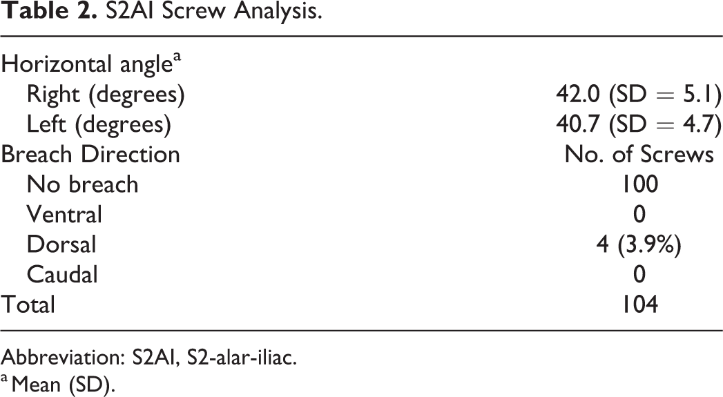
Abbreviation: S2AI, S2-alar-iliac.
a Mean (SD).
In all 4 cases of Castellvi III (IIIa, 1; IIIb, 3), preoperative planning with navigation software revealed that S2AI screw insertion was difficult if S1 pedicle screws were placed. Therefore, S1 pedicle screws in these 4 cases were skipped (Figures 4A-4G).
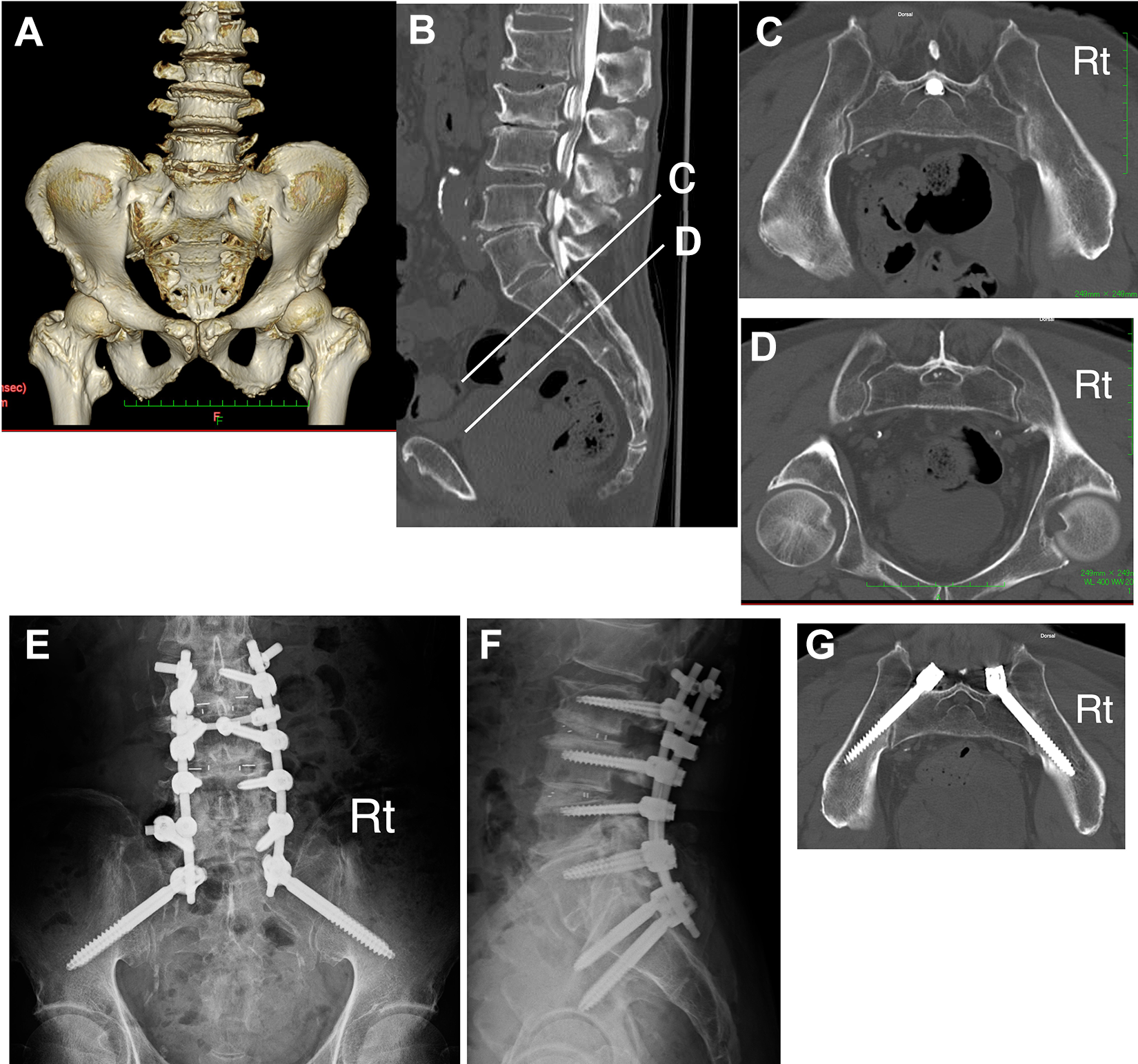
Castellvi IIIb in a 75-year-old man. A. Three-dimensional computed tomography (CT). B. Sagittal reconstructed image of CT myelography. C. Axial image at the level corresponding to the S1. D. Axial image at the level corresponding to the S2. E and F. Postoperative X-ray images. G. Postoperative CT image. Preoperative 3-dimensional CT demonstrates that this lumbosacral transitional vertebra is Castellvi IIIb because the bilateral transverse processes of the L5 fuse completely to the sacral alae. Although in the sagittal image (B) S2 appears to be at level (D), when compared with axial images (C) and (D), it is clear that level (C) is the true S2 anatomically. S2-alar-iliac screw placement at level (D) would be difficult. Postoperative CT shows no cortical breach of the screws.
A total of 11 patients (21.2%) required offset connectors when the S2AI screw was secured to the rod to avoid repeated bending of the rod: 2 of these patients required offset connectors bilaterally. Of the 104 screws, 4 (3.9%) breached dorsally: that is, 2 protruded to the dorsal cortex of the ilium between 3 and 6 mm, and the other 2 protruded more than 6 mm. All screw breaches were identified in female patients. Screw breaches were not detected in patients with the lumbosacral transitional vertebra. No screw-related complications were observed.
Discussion
We introduced our technique of S2AI screw placement assisted with a guidewire using a new anatomical landmark. To improve the screw placement accuracy, first we easily confirmed the tip of the greater trochanter during screw placement (Figure 1). This is very important because the tip of the greater trochanter is a landmark of the screw angle in the caudal direction. Second, we inserted a guidewire into the ilium along the sacral tuberosity from the extra-articular portion of the sacroiliac joint just lateral to the ideal screw entry point toward the tip of the greater trochanter and used it as a guide for the screw trajectory. Finally, 1-shot pelvic inlet and lateral pelvic X-ray images were taken to confirm the direction of the guidewire, and the screw trajectory was adjusted as necessary. The rate of the screw breach in this study (3.9%) was not less inferior to that in other free-hand techniques (3.0%-8.5%) and image-guided techniques (0%-4.3%). 3,6,8 -10 Therefore, the presented technique needs no protective gear and can be carried out at a lower operating cost than the expensive robotic guidance or surgical navigation and without sacrificing precision.
Nonfluoroscopic free-hand techniques do not expose the surgeons and their team to radiation and do not require wearing of protective gear. However, free-hand techniques have drawbacks. Postacchini et al 11 described that the joint space width of the sacroiliac joint varied with each patient because of constitutional characteristics and degenerative changes. Previous studies did not report controversy concerning an anatomical landmark of the entry point of the screw. 4,5,8,9 A target of the screw trajectory in the caudal direction is also described, such as the tip of the greater trochanter and the anterior inferior iliac spine, whereas no article has mentioned reliable signposts or anatomical landmarks of the screw angle in the ventral direction. Determining the screw trajectory in the ventral direction by just aiming at the tip of the greater trochanter is difficult. That is, even if the sacroiliac joint is penetrated successfully, there is a possibility of deviation to the dorsal, ventral, or caudal directions. The reported horizontal angle—angle in the ventral direction—was 37.3° ± 4.3°, 9 39.3° ± 8.2°, 8 and 41.1° ± 8.1° (free-hand technique) and 42.8° ± 6.6° (robotic guidance) 10 on average, but this data was obtained from CT-based measurements. These CT-based data simply showed the screw angle and did not reflect variability in the morphology of the sacroiliac joint; thus, they may not be very helpful in the operative field.
As shown in Figure 2, the articular and extra-articular surfaces of the sacroiliac joint are not parallel to each other, so the guidewire can certainly enter the ilium if it is inserted along the sacral tuberosity. Thus, the use of the guidewire allows surgeons to place the screws easily under a less stressful setting. Along the course of the insertion, taking 1-shot pelvic inlet and lateral pelvic X-ray images is recommended because the guidewire is not always in the most appropriate direction.
In the present study, 4 dorsal breached screws (3.9%) were identified in female patients. Nishi et al 12 reported in their cadaveric study that the size of the iliac auricular surface was significantly larger in males than in females. 12 Because the screw entry point is always slightly medial to the guidewire, if the size of the sacroiliac joint is small, the screw must be inserted more dorsally than the guidewire to prevent ventral breach. Therefore, even with our technique, the screw may breach the dorsal cortex of the ilium. However, there were no screw-related complications, and thus, no additional surgery had been attempted.
The reported incidences of numerical variations of lumbar vertebrae and that of lumbosacral transitional vertebrae were 3.3% to 5.5% and 7.7% to 10.6%, respectively. 13 -17 The preoperative recognition of these lumbosacral variations is crucial to prevent wrong-level surgery. Navigation software is not only able to simulate whether the S2AI screw can be inserted, but also is able to detect lumbosacral transitional vertebrae. 18,19 As shown in Figure 4, the use of navigation software is particularly helpful for Castellvi III cases.
This study has some limitations. Our study population was limited to patients with degenerative diseases with relatively normal pelvic and sacral anatomy, and we did not include patients with spinal deformities with pelvic and sacral dysplasia, regardless of whether it was a degenerative disease or not. Because these spinal deformities may each have unique morphology in the sacroiliac joint, it would be wise for surgeons to choose image-guided techniques over free-hand techniques. Therefore, it is prudent to simulate whether the S2AI screw can be inserted with free-hand techniques, if possible, using navigation software. A larger cohort would be needed to assess the value of this new technique. Although the technique relies on the morphology of the sacroiliac joint, there have been few anatomical articles on its morphology from the viewpoint of screw placement.
Conclusions
We presented our technique for S2AI screw placement assisted with a guidewire using a new anatomical landmark. The guidewire assistance avoided the use of C-arm fluoroscopy and facilitated screw insertion under less stressful conditions. Because the guidewire can be inserted at an angle according to the individual morphology of the sacroiliac joint, it is highly reliable as a guide for the screw trajectory. The presented technique would help improve the accuracy of S2AI screw placement.
Footnotes
Acknowledgments
We would like to thank Dr Shigeo Sano from the Department of Spine Center at Sanraku Hospital, Tokyo, Japan, for his special advice about the free-hand technique for S2AI screw placement, and Dr Akiko Nomura (International SOS) for English language refinement. We would also like to thank Editage for English language editing.
Declaration of Conflicting Interests
The author(s) declared no potential conflicts of interest with respect to the research, authorship, and/or publication of this article.
Funding
The author(s) received no financial support for the research, authorship, and/or publication of this article.