
Abstract
Introduction:
Ultrasound is a promising new approach for noninvasive brain stimulation. Low-intensity focused ultrasound (LIFU) allows targeting the deep brain with high spatial and temporal resolution. For clinical use, ultrasound systems must fulfill specific requirements. Three-dimensional (3D) steering and focusing either requires mechanical displacement of (focused) transducers or multielement arrays and corresponding multichannel electronics. Since the waveform has an impact of the induced neurostimulation effect, electronics need sufficient flexibility for generating arbitrary temporal signal patterns. For compensation of skull aberration artifacts, elements must be excited with defined phase resulting of phase aberration correction (PAC) algorithms. Finally, for being clinically usable, systems must be combined with planning hardware and software.
Methods:
A versatile system for 3D steered LIFU based on two-dimensional matrix arrays was designed, fabricated, and characterized in terms of focusing, steering, and output of temporal patterns. Our PAC algorithm was validated on an ex vivo skull. The system was tested for compliance with defined medical device standard by accredited laboratories, and an initial Magnetic resonance imaging (MRI) phantom study was performed.
Results:
Our system allows 3D beam steering and focusing with lateral focus sizes down to 4 mm, which is less than the size of a human gyrus, such that detailed targeting is possible. Arbitrary temporal signal patterns (different wave forms, pulse length, duty cycle, and ramping) were generated. Different software interfaces allow patient-specific planning with a Magnetic resonance Tomograph (MR)- or neuronavigation-based workflow, in which a custom-developed PAC algorithm allows compensation of the skull bone. The absence of transducer susceptibility artifacts was shown in the MRI phantom study, and the acoustic focus was localized using magnetic resonance acoustic radiation force imaging.
Discussion:
Our new versatile ultrasound neuromodulation platform represents a compromise between conformal helmet-like systems and single element transducer setups. It is flexible in terms of spatiotemporal stimulation patterns and can be accommodated to different workflows.
Impact Statement
Progress in the field of ultrasound neurostimulation is depending on the availability of suitable hardware fulfilling a range of practical, technical, safety, and regulatory requirements. Systems must fit in established clinical workflows (e.g., usable with MR and/or neuronavigation systems), allow accessing deep brain regions, and generate defined spatiotemporal ultrasound patterns. Furthermore, basic regulatory constraints (e.g., IEC 60601-1) must be fulfilled. Our new low-intensity focused ultrasound (LIFU) system addresses these requirements and is flexible enough for use in a research environment. It was developed for facilitating the clinical transfer of LIFU and helping to gain a better understanding of underlying effects in ultrasound neurostimulation.
Introduction
In recent years, ultrasound has shown to be a promising therapeutic option for a range of conditions such as neurodegenerative diseases (Darrow, 2019; Meng et al., 2021), movement disorders (Bancel et al., 2024; Elias et al., 2016; Moosa et al., 2019), Alzheimer’s (Leinenga et al., 2016), psychiatric diseases (Bubrick et al., 2022) or even stroke (Zafar et al., 2019; Yuksel et al., 2023), and chronic pain (Hameroff, et al., 2013). The underlying effect differs between applications and can range from targeted drug delivery (Deckers and Moonen, 2010), opening of the blood–brain barrier (Konofagou et al., 2012), hyperthermia (Diederich and Hynynen, 1999), and mechanical or thermal ablation to neuromodulation (Blackmore et al., 2019; Dallapiazza et al., 2018). In particular, the ability to modulate neuronal activity with a noninvasive and high-spatial resolution method not only offers new therapeutic avenues but also at the same time paves the way toward new insights to the healthy brain. The current gold standards in brain stimulation are deep brain stimulation (DBS) and electrical (transcranial direct current stimulation tDCS (Utz et al., 2010)) or magnetical (transcranial magnetic stimulation) TMS (Kobayashi and Pascual-Leone, 2003) stimulation, which have intrinsic limitations. Although DBS is well established [>5000 implantations/year in the United States (Sarica et al., 2023)], it is associated with risks of the surgical procedure such as infection or hemorrhage. In contrast, TMS and tDCS lack penetration depth, targeting precision, and spatial resolution, making it very challenging to selectively target deep brain regions (Saturnino et al., 2019). By contrast, the ability of focusing ultrasound waves allows targeting much more spatially confined areas in the brain. However, being able to deliver focused ultrasound waves has some implications on the design of ultrasound systems. A first option consists in using single element focused transducers, in which the curvature of the transmit aperture defines the focusing properties. Such systems have the drawback of not allowing to adjust the focus position in an easy way. Targeting another brain region requires mechanical displacement of the transducers. Obviously, dynamic switching between different focus positions is prohibited by such setups. Furthermore, the specific skull anatomy leads to distortion of the pressure distribution field and, thereby, diminishes the accuracy of focusing. This can only be compensated when using multielement array transducers addressed with individual delays. For this purpose, algorithms for so-called phase aberration correction (PAC) (Leung et al., 2021; Wang et al., 2025), for instance, based on simple ray-tracing approaches (Flax and O’Donnell, 1988), the Rayleigh–Sommerfeld Integral (Hynynen and Sun, 1999), or full wave inversion (Bancel et al., 2021), have been presented in the past.
When aiming at optimizing the focusing properties, helmet-like systems with a large number of distributed transducers are the ideal approach. Such a configuration has been initially developed (ExAblate Neuro, Insightec, Tirat Carmel, IS) for ablation in the context of Parkinson’s and essential tremor treatment. Using this 1024 element phased array based system operating at 650 kHz, precise local thermal ablations of 4 mm in diameter could be produced in the brain under Magnetic resonance Tomograph (MR)-guidance (Martin et al., 2009). The ExAblate system has been used in a low-intensity focused ultrasound (LIFU) setting as well using a 220 kHz array, where sensory evoked potentials were inhibited in the swine thalamus (Dallapiazza et al., 2018). Another skull conformal array has been developed based on 2 × 2 modules consisting of 64 element two-dimensional (2D)-phased arrays integrated into a patient-specific three-dimensional (3D)-printed scaffold (Adams et al., 2021). Very recently, a helmet-like device (Martin et al., 2024a) with 256 elements allowing precise focusing (1.5 mm average focus shift, 24 mm³ focal volume) across a wide range of target positions in the brain was presented.
While such helmet-like configurations are the best choice when it comes to generating a small almost isotropic focus, acoustic coupling remains challenging and mostly can only be solved with a water layer between the elements and the skin. An alternative option is the use of a 2D matrix array. Such transducers as well allow 3D focusing and steering and can be more easily coupled to the skin using a (hydro-)gel or silicon pad. For instance, a system based on 252 elements in two spherical phased array transducers mounted to an MR compatible plastic frame has been recently used for deep brain focusing (Riis et al., 2024). A main drawback is the nonisotropic focusing as follows: while precise focusing can be achieved in x and y dimension, the focus is typically elongated in the z dimension.
In this work, we present a new versatile system optimized for research in ultrasound neuromodulation. The system comes with a 256-element matrix array transducer for 3D beam steering; however, its flexible architecture allows driving 2 transducers in a cross-beam setup for instance. Different workflow options (based on MR guidance or a neuronavigation setup) are implemented, and a custom PAC algorithm has been developed and tested. The system has been characterized with respect to focus size, steering angle, accuracy of the generated temporal signal patterns, and PAC.
Materials and Methods
System overview
The multichannel ultrasound neuromodulation system consists of three hardware components (Fig. 1) as follows: the transducer, the power supply unit, and the signal generating unit. Depending on the application (MR- vs. neuronavigation guided), they are mounted together on a MR-compatible medical device cart or the power unit, containing non-MR compatible components such as the power supplies, which are detached from the cart and placed away from the magnet. The laptop-controlled system foresees different interfaces all being electrically isolated from the electronics using electrical to fiber optic converters.
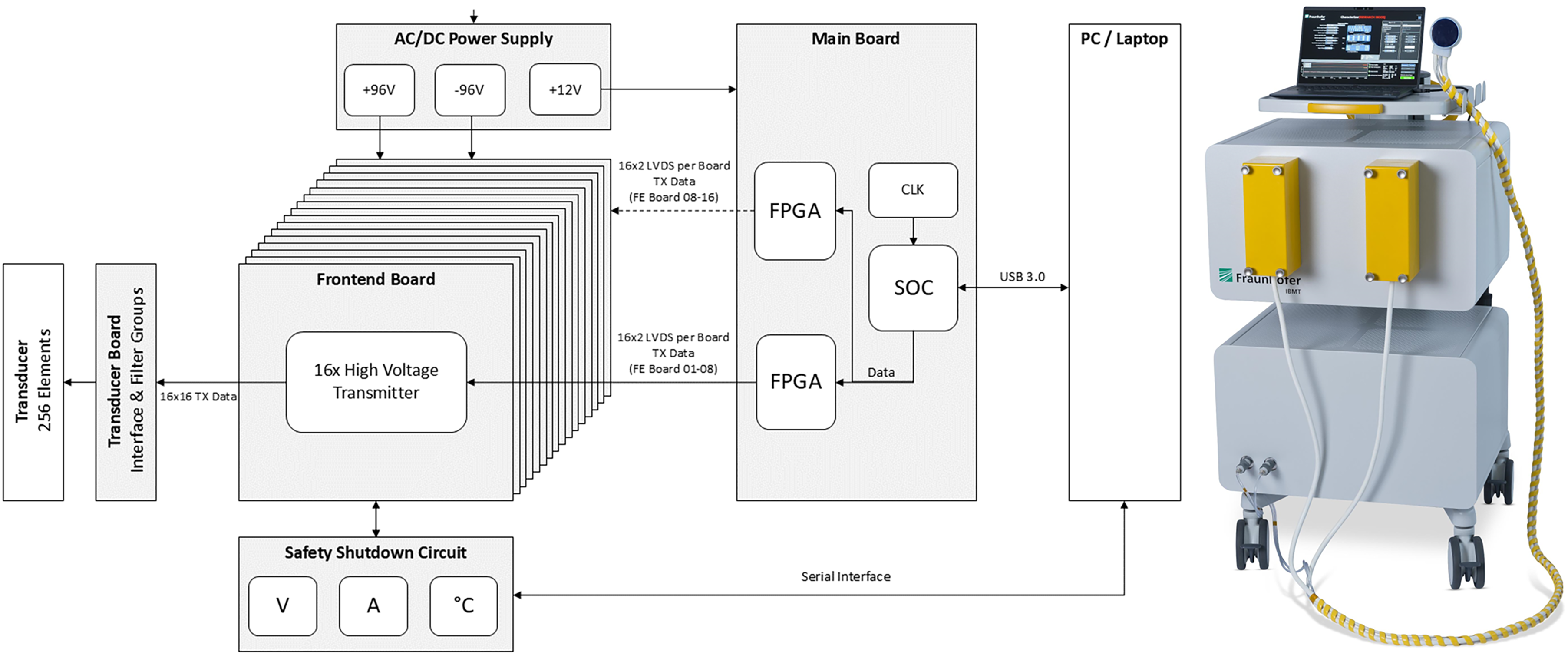
System diagram with the different hardware modules (left) and integrated system on medical device cart (right). AC/DC, alternating current/digital current; FPGA, field programmable gate array; SOC, system-on-a-chip; CLK, internal Clock (generator); V, Volt; A, Ampere.
Transducer
The design goals of the transducer were such that a target pressure of up to 0.5 MPa should be achieved at a focus depth between 20 mm and 100 mm, allowing even deep brain structures such as the hippocampus to be targeted. Furthermore, the maximum number of elements was limited to 256 for matching the channel count of the electronics. Further target metrics were a lateral focus size <5 mm and a steering range of ∼ ± 15°. The frequency has been set to 500 kHz because of previous work reporting successful neurostimulation at this frequency (Ennasr et al., 2024) and since it represents a good compromise between targeting precision (which increases with higher frequency) and losses due to attenuation in the skull (being lower for lower frequencies) (Zadeh et al., 2024; Legon and Strohman, 2024). Higher frequencies, despite being interesting with a view on sharper focusing, were disregarded due to stronger attenuation in skull tissue and limited aperture size (small pitch) required for off-axis beam steering resulting itself in lower achievable pressure ranges.
Simulation
All simulations were conducted for continuous wave excitation since this represents a good approximation of the high burst-count signals typically used in neurostimulation applications. Two types of simulations were performed. For definition of the ideal array geometry, the pressure distribution is calculated based on the Rayleigh–Sommerfeld integral (Equation 1).
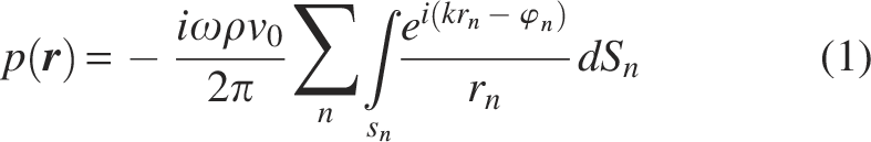
Here r is the point of interest at which the pressure is calculated, rn is the distance between the evaluation point r and the source point in the n-th active element of the aperture, and
For optimization of the individual array element, a simulation using the finite element analysis tool PZFlex (Weidlinger Associates Inc., USA) is performed. The array elements were modified with respect to the used material (PZT 5H vs. PZT 8), element subdicing, and thickness. The output pressure for a given excitation voltage was taken as optimization criterium.
Transducer setup
In the presented configuration, the system is equipped with a 500 kHz circular-shaped 2D matrix array (diameter 55.4 mm). The transducer made of a hard piezoelectric material with high mechanical quality factor has 256 active elements, grouped in two subapertures with 128 elements each—an inner circle with a diameter of up to 43 mm and an outer ring-like aperture with a width of 2–3 elements as shown in Figure 2B. The two subapertures are individually contacted with one 128-channel µ-coax cable (cable length 3.5 m, ITT Cannon connector). A common ground layer covers the front of the aperture. The pitch of 3.08 mm was realized with deep trenches between the elements to suppress cross talk and, thereby, optimize the steering and focusing characteristics of the array. The targeted frequency was realized by iterative grinding and measuring the spectral response. After integration of the acoustic block into the 3D printed housing, a coupling and protection layer made of polyurethane is applied on top of the ground electrode. Finally, a mechanical adapter for application of a (soft silicon) coupling pad is added, so that coupling to nonplanar surfaces is improved. An integrated cooling system is realized from the backside of the transducer. It removes efficiently thermal energy developed due to losses in the transducer by running a liquid cooling media through it. Extra-sensitive and fast thermistors are integrated in the arrays and are constantly measuring the temperature to detect overheating. The housing is shielded by introducing a thin layer of conductive material on the inner side to reduce interferences when driving the transducer in an MR environment as much as possible. Furthermore, four commercial passive MR-visible markers (PinPoint, Beekley Medical, USA) are integrated into the housing such that the transducer position and orientation can be extracted from MR-planning data. They are arranged in a nonsymmetrical pattern (Fig. 2D), so that a single and well-defined 4 × 4 matrix describes the transformation between the coordinate systems of the aperture and of the MR data (which is identifiable via the 4 marker positions).
Multichannel driving electronics
Electronics development
Our so-called TheraPhAS is designed for generation of bipolar signals with defined delay for each transducer element with customized spatiotemporal sonication patterns. The system is split into two modules as follows: a custom power supply (including the cooling unit) and the actual high-power multichannel system (including a safety monitoring board). It has different triggering options (IN/OUT) for synchronization with external readout devices (e.g., ultrasound imaging, MR, EEG), which are all fiber optics based to reduce potential noise (e.g., when the system is used in an MR environment).
The multichannel electronics module is based on 16 in-house developed power pulser boards, each generating 16 transmit signals, and an in-house developed main board for control of the power pulser boards acting as interface to a personal computer (PC). The transmit signals can be arbitrarily programmed by the user in terms of frequency, phase, ramp up/down, burst count, and repetition frequency. The pulser consists of metal-oxide-semiconductor field-effect transistor stages, which switch through either a positive or a negative digital current (DC) voltage (up to ± 96 V) and, thus, generate bipolar square wave signals. Accordingly, no native amplitude modulation is possible. However, pulse width modulation can be realized with the system clock of 120 MHz, finally resulting in amplitude modulated ultrasound patterns. The main board integrates different integrated circuits such as a ZYNQ system-on-a-chip and two additional field programmable gate arrays (FPGAs) (ARTIX, Advanced Micro Devices Inc.) as a resource extension. It manages the distribution of the transmit data to the corresponding power pulser boards.
For focusing and steering, delay sets are generated in the software and passed to the FPGA of the main board, where the corresponding phase-adjusted transmit patterns are generated. The system allows single point or dynamic focusing (switching between focus positions at rates faster than 1 kHz). A system safety board has been developed that is able to continuously monitor transmit voltages, transmit currents, flow speed of the water-cooling unit, as well as transducer and electronics temperatures. In an event of an error, the running transmit sequence will be immediately aborted by switching off the transmit voltages.
The second module of the electronics includes medical grade DC voltage supplies (CX18M, Advanced Energy, Denver, USA) and in-house developed the cooling unit for the ultrasound transducer.
Software
Signal parameterization
The system supports multilevel definition of the temporal pattern using the nomenclature suggested by the iTRUSST consortium (Martin et al., 2024a). The number of cycles and the ramp up/down duration define the basic pulse. Then, the number of pulses and the pause between pulses define the pulse train. Finally, the repetition frequency and pause between such pulse trains can be defined. All this can be done in a custom user interface (UI) or can be integrated into a third-party application by means of a C++ software development kit (SDK).
Delay generation
The most crucial part when exciting an ultrasound transducer for stimulating a defined Region of Interest (ROI) is calculation of transmit delays. In a medium where the speed of sound can be assumed as relatively constant (e.g., in a water tank or soft tissue), delays can be calculated based on time-of-flight considerations. However, in the context of brain stimulation, the skull bone with its heterogeneous structure and high speed of sound leads to a significant distortion of the pressure field (Kyriakou et al., 2014). Accordingly, delays for accurate focusing through the skull bone must be calculated based on a patient-specific therapy setting. For this purpose, we prepared software interfaces allowing a planning of the sonication in an MR-guided and a neuronavigation system-based setting.
MR-guided planning
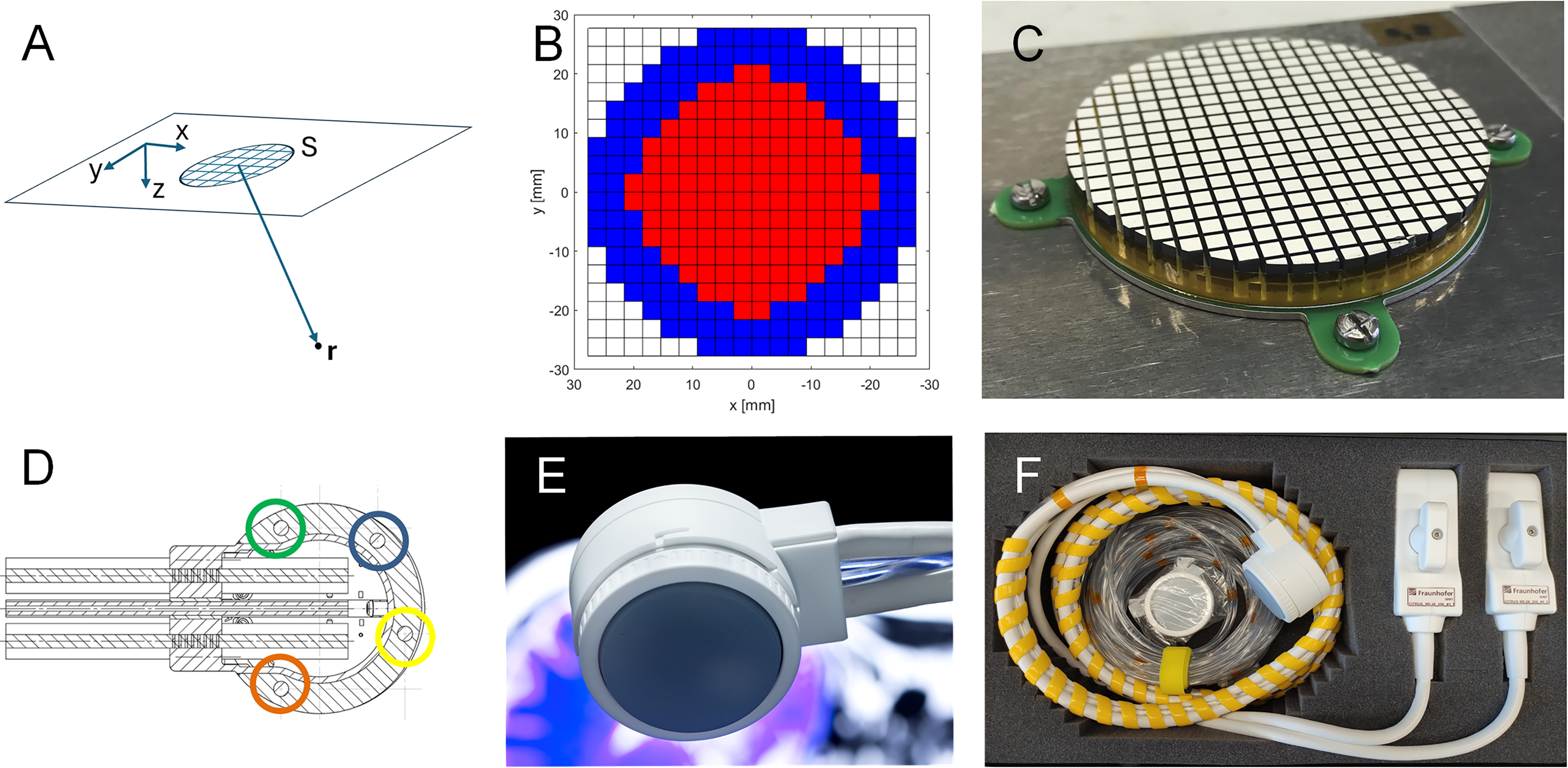
Both planning scenarios rely on the availability of skull bone data and the position of all transducer elements in the same coordinate system. For the MR-guided planning scenario, the process is illustrated by Figure 3. Briefly, the steps are the following:
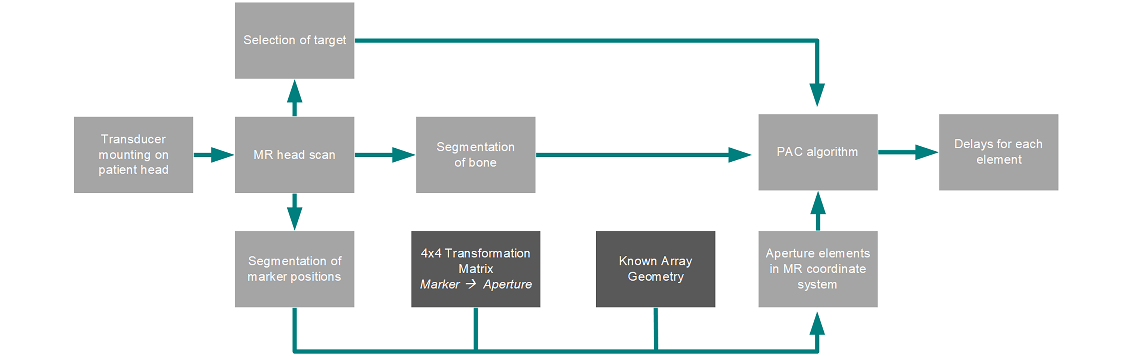
Chart of the processes involved in the planning in the MR workflow. Planning steps are in light gray. Needed data serving as input in calculation of the delays are shown in darker gray.
Acquisition (or loading) of an MR dataset of the patient head with the transducer already mounted on the head. No stereotactic frame is needed since the transducer position is retrieved from the MR data in the next step.
Manual extraction of the 4 MR fiducial center positions from the MR data
Computation of the position of all transducer elements based on the fiducial positions and the 4 × 4 coordinate transform matrix based on Computer Aided Design (CAD) data
Segmentation of the skull bone from MR data
When these steps are performed, the transducer element positions and the skull bone position can serve as input for the delay calculation function based on our simplified time reversal approach (Bost et al., 2023). The algorithm segments the volume of interest into soft tissue and bone and assumes a point source in the target coordinates
Again, the signals
Neuronavigation system-based planning
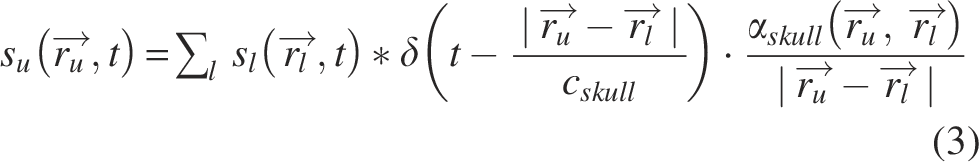
The above-mentioned SDK allows integration into commercial neuronavigation solutions (Fig. 4). In such a neuronavigation setup, the current 3D position and orientation of the transducer in the coordinate system of the MR dataset are acquired by some tracking tool (e.g., optical tracking/Near-infrared radiation (NIR) camera). After segmentation of the skull bone data using a gradient-based edge detection (measuring the rate of change of intensity of the MR voxels), delays are calculated by our integrated PAC algorithm or using commercial tools such as k-plan (Brainbox Ltd, Cardiff, based on the open-source toolbox k-wave) (Treeby and Cox, 2010).
Integration of sonication planning in a neuronavigation solution (courtesy of Localite GmbH).
Characterization setup
Transducer characterization
For characterization of the array, its homogeneity, the spectral response, and the output pressure as a function of driving voltage and focus depth were assessed in a water tank and a programmable 3-axis scanner using a calibrated hydrophone (RP10s, RP Acoustics, Germany). For measuring the array homogeneity, elements were individually excited, and the generated signal was detected by the calibrated hydrophone placed in front of each element (on the acoustic axis of each element). For the characterization of the spectral behavior, elements were excited with a pulser (Panametrics 5800 PR) with a monopolar pulse of a duration shorter than 100 ns, and the Fourier transform of the hydrophone signal was calculated by means of the fast fourier transformation (FFT) method implemented in MATLAB (Frigo and Johnson, 1998). The frequency of maximum amplitude in the spectrum is defined as the array center frequency. The focusing and steering properties of the array were assessed with the same hydrophone. XZ and XY pressure distribution scans were performed for different target focus positions, which were then compared with the experimentally measured position of maximum pressure. The same data were used for assessment of the focus sizes in X- and Z direction. Finally, the steering properties were assessed by steering the focus away from the acoustic axis, but still in the XZ plane. The occurrence and level of grating lobes (compared with the pressure maximum in the main lobe) were used for rating the steering capabilities.
The ability of the electronics to generate delay sets for focusing and steering ultrasound waves was tested in pressure distribution scans as described above. When it comes to the testing of dynamic focusing, we positioned a plastic cup filled with water on the transducer and set the focal distance approximately on the water surface. The focus positions were defined such that the different focal points are on a circle with a radius of 3 cm and the sequence was such that 360° is scanned within 4 sec. A video sequence of the water surface was then captured.
Validation of PAC
For proof of concept of PAC, we chose the MR guided setting. First, a phantom made of an ex vivo human skull embedded in an agarose matrix was realized. The skull has a thickness of approximately 7–8 mm and was watered and degassed for several hours before the integration into the phantom. An MR dataset of the phantom was acquired on a Siemens 3T Magnetom Prisma Fit (sequence: 3D T1w Magnetization-prepared rapid Gradient Echo (MP-RAGE), Repetition Time (TR)/Time to Echo (TE)/Inversion Time (TI) = 1760/2.63/900 ms, α = 8°, Field of view (FOV) = 230 × 230 mm, 240 slices, voxel size 1.0 × 0.72 × 0.72 mm³, Bandwidth (BW) 250 Hz/Px). The transducer is positioned at the vertex of the skull. While the segmentation is based on a T1 sequence in the phantom experiment, a ZTE sequence (Delso et al., 2015) should be used in a clinical setting to obtain the skull contrast required for precise segmentation. The fiducials integrated in the transducer housing were segmented in the MR data and used for calculating the positions of the array elements using the known 4 × 4 transformation matrix. Next, the skull bone anatomy is extracted from the MR data using an edge detection algorithm, so that the lower and upper skull surfaces are available in a common coordinate system with the array element positions. Delays for each element for targeting a given focus position were calculated using our PAC algorithm. The phantom with the skull and the transducer was then placed in a water tank (after removal of the agarose, such that a needle hydrophone can be scanned below the skull), and pressure distribution fields (with and without PAC) were measured.
Testing of MR compatibility
The system was designed to be used in a neuronavigation- or MR-based workflow, where the MR scan should be acquired before ultrasound neurostimulation. However, MR can as well play a relevant role in monitoring of neuromodulation using magnetic resonance acoustic radiation force imaging (MR-ARFI) or Blood-Oxygenation-Level Dependent (BOLD) sequences. For instance, MR-ARFI allows to track tissue displacement induced by acoustic radiation force analyzing the phase of an MR image (Odéen et al., 2025) and is therefore a promising candidate as monitoring technology for in vivo brain sonication (Kaye et al., 2011; Hertzberg et al., 2010; Mohammadjavadi et al., 2024). However, being able to use the ultrasound neurostimulation device in an MR environment induces some significant demands with respect to system design and materials used. To evaluate the system in an MR environment, the ultrasound transducer was immersed in a Copper sulfate (CuSO4) solution (1.5 g/L CuSO4 and 9 g/L sodium chloride (NaCl) in ultrapure water) together with a half-inch diameter nylon reference rod. The phantom (Fig. 10A) was imaged with a 3T Siemens MR scanner and a flexible body coil (Fig. 10B). For reducing the susceptibility effects, materials, connectors, cables, and integrated Negative-temperature-coefficient thermistors (NTCs) inside of the transducer were carefully chosen for being iron and nickel free. In this study, Figure 10D, E represents a T1 Gradient Echo and T1 MP-RAGE sequence. In addition, the transducer and the electronics have been characterized as suggested by the ASTM 2052 standard. For this purpose, they were suspended in the magnetic field of the tomograph, and the deflection from the vertical was measured.
Next, as a proof of concept of using MR-ARFI as monitoring method, we investigated the ability to localize the acoustic focus position. For this purpose, the matrix array was fixed to a soft tissue-mimicking phantom (Computerized Imaging Referencing System, Virginia, USA), and ultrasound was focused to a depth of 80 mm (free-field peak-negative pressure of 2.37 MPa) to generate micro-displacement in the phantom. MR images were acquired on a 3T scanner (DV750, GE Healthcare, Milwaukee, WI) with spin echo sequences. Inverted bipolar motion encoding gradients were used, with a total duration of 20 ms. During MR-ARFI, two 6 ms ultrasound pulses with 15 ms in between (repetition of the pulse train every 500 ms) were applied during the second lobe of the first bipolar and the second lobe of the second inverted bipolar motion encoding gradient. We utilized a time series approach with a single-shot spiral-out MRI sequence, acquiring 100-time frames with TR/TE = 500 ms/40 ms, 5 slices of 4 mm thick, reconstructed 128 × 128 matrix, and scan time 80 sec. The used MR-ARFI method is described in detail in Mohammadjavadi et al., (2024). Briefly, a block design, similar to those used in Functional magnetic resonance imaging (fMRI) studies, was used to alternate ultrasound stimulation on and off in blocks of 25 time frames. The resulting Statistical Parametric Maps were expressed as T-scores, representing the likelihood that the observed time series matched the expected block design pattern.
Results and Discussion
Transducer characterization
Array performance
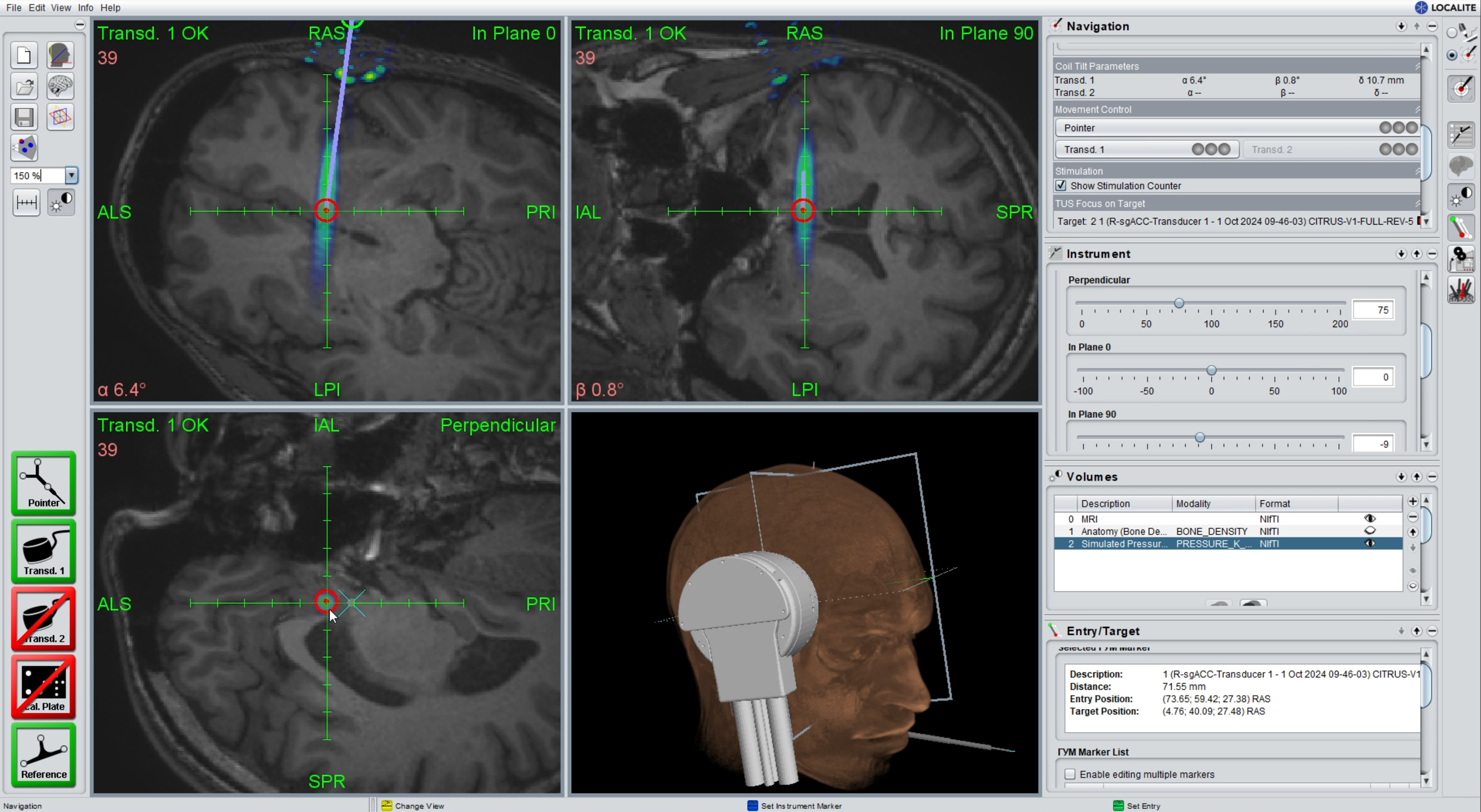
The sensitivity distribution over the aperture in Figure 5 shows that there are no inactive elements, and a standard deviation of 13% was measured.
Next, the pressure output of the array was assessed for different focusing depths and excitation voltages. The pressure level shows a maximum when focusing around 40–50 mm, which then drops continuously and reaches approximately 75% of the maximum level at the depth of 100 mm. The linearity of the pressure output as a function of the excitation voltage was characterized by applying 30 cycles of burst signals and measuring the effective pressure. In the investigated voltage range of 10–96 V, the pressure is linear in the applied voltage until 90 V and seems to flatten then. This measurement was performed for the depth of highest pressure, such that the measured 3 MPa effective pressure can be considered as the maximum pressure that can be generated with the presented electronics/transducer configuration. We furthermore characterized the spectral response of the system by exciting single elements with a pulser and measuring the resulting impulse response. The Fourier Transform of the impulse response yields a center frequency of 485 kHz and a −6 dB bandwidth of 66 kHz.
Focusing and steering
The focusing and steering properties of the transducer were determined in free-field (water tank) measurements. Figure 6A–C shows the measured pressure fields, with the focal region becoming more elongated for deeper focus positions. While the lateral focus size (defined by the FWHM) is between 3.7 mm and 7.4 mm, the axial focus size increases from 21.2 mm to 85.0 mm. In addition to the focus size, the steering range of the transducer was characterized. For this purpose, different steering angles between 0 and 22° were set, and angular scans were performed. As can be seen in Figure 6D, significant grating lobes peaking at −10 dB with respect to the actual focus appear when steering to 17° or more. Both the grating lobe and the increasing lateral focus extent can be seen as well in the XY pressure distribution scans performed in different axial distances as can be seen in Figure 6E–G. Tables 1 and 2 show that the measured focusing and steering metrics are well in agreement with simulation performed based on the Rayleigh–Sommerfeld integral as described in section 2.2.1, Simulation.
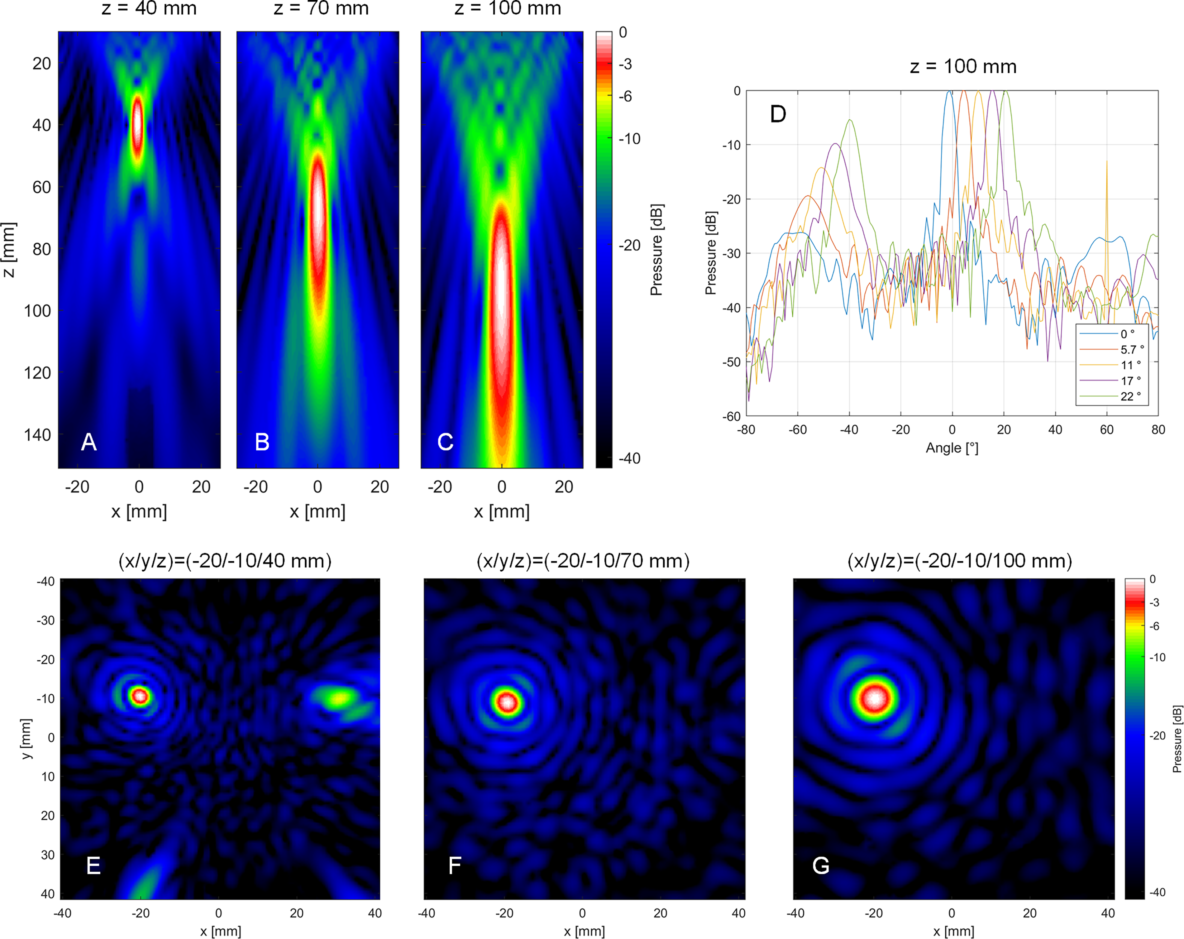
Measured XZ pressure distribution field when the entire aperture is excited with a 30-cycle burst signal focus at different depths on the acoustical axis of the aperture
Comparison of Experimental and Numerical Metrics for Different Focus Positions
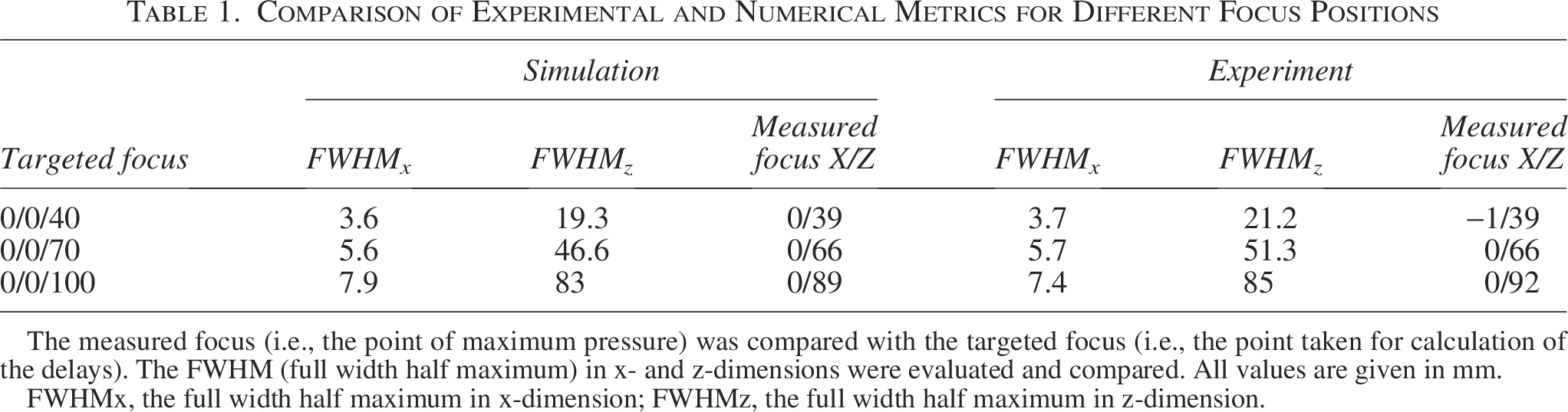
The measured focus (i.e., the point of maximum pressure) was compared with the targeted focus (i.e., the point taken for calculation of the delays). The FWHM (full width half maximum) in x- and z-dimensions were evaluated and compared. All values are given in mm.
FWHMx, the full width half maximum in x-dimension; FWHMz, the full width half maximum in z-dimension.
Comparison of Experimental and Numerical Steering Metrics
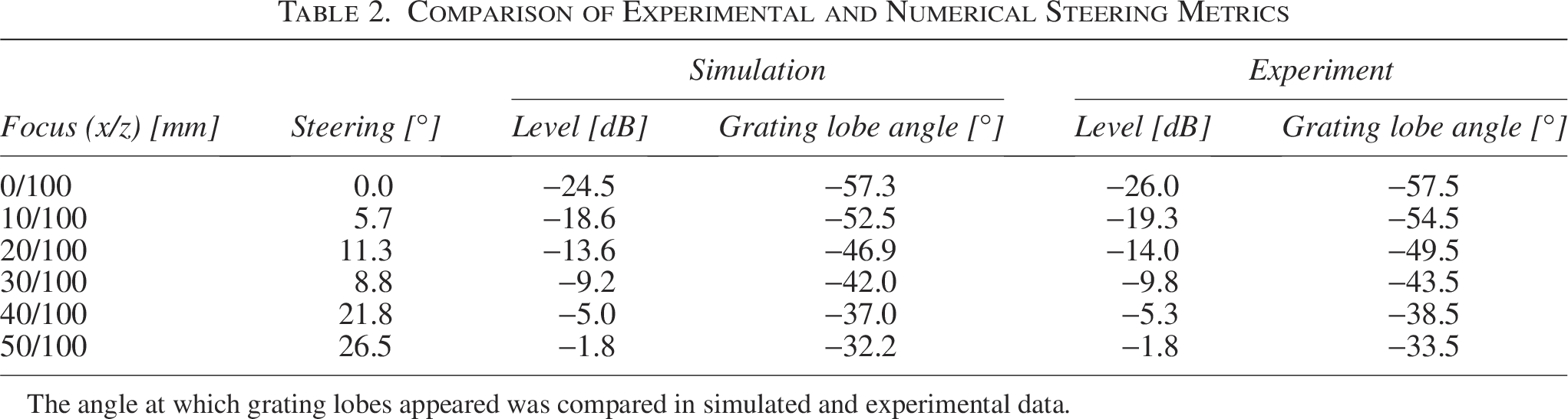
The angle at which grating lobes appeared was compared in simulated and experimental data.
Signal fidelity
The system has a wide range of capabilities for generating customized stimulation sequences for different brain targets and research questions. In this example, we defined a signal with a pulse train repetition duration of 1 sec, where each pulse train consists of 10 pulses of varying duration. The focus was set to 0/0/50 mm, and a calibrated hydrophone was placed in the focus. Figure 7 shows examples of measured single pulse signals of 100 µs, 500 µs, 1 ms, and 5 ms, as well as a pulse train and its repetition. The data show that the actual duration of the pulse corresponds to the defined one with minor differences resulting of the limited transducer bandwidth (and the corresponding ramp up and ring down duration).
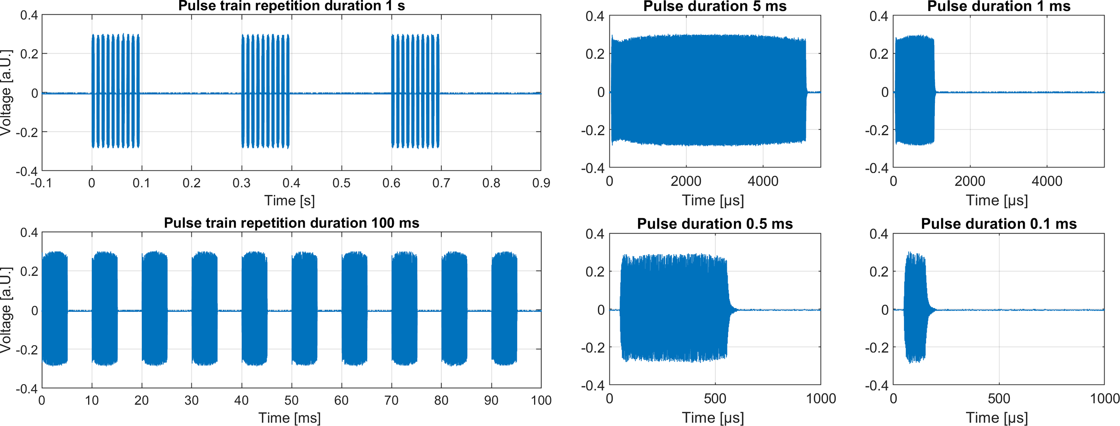
Measurement of different signal patterns with different pulse train duration and varying pulse duration.
Dynamic focusing
Figure 8 shows screenshots in time steps of 1 sec, where the focal point can be recognized as bubbles on the water surface at positions of −90, 0, 90, and 180°. The duration of 4 sec for a 360° scan was chosen slow enough to be able to easily capture the focus displacement with a camera. However, switching between different focus positions (for instance, left and right brain hemisphere) can be performed much faster up to kHz rates.
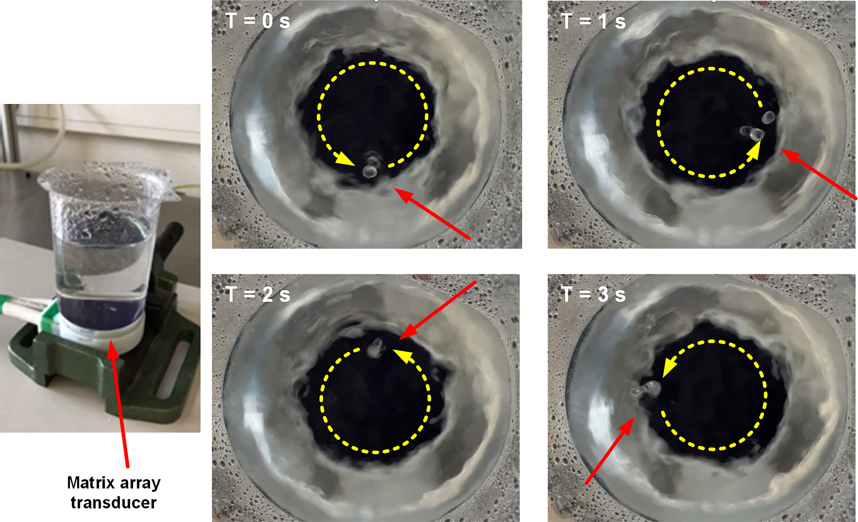
Proof of dynamic focusing with focus migration over 360° along a circular shape within 4 sec.
PAC
For 3 different focus positions, an XY pressure distribution field was scanned below the skull bone, showing the severity of the field distortion caused by the skull, as well as the ability of the PAC algorithm to refocus the pressure waves on the defined target point (Fig. 9). While the free-field XY −6 dB focus size was 44.1 mm2, it increased to 132–139 mm2 in the uncompensated scans. Using PAC resulted in a focus size of 42–48 mm2 again. In addition, the focal pressure increased by 40% to 63% when using PAC in our 3 experiments (Table 3).
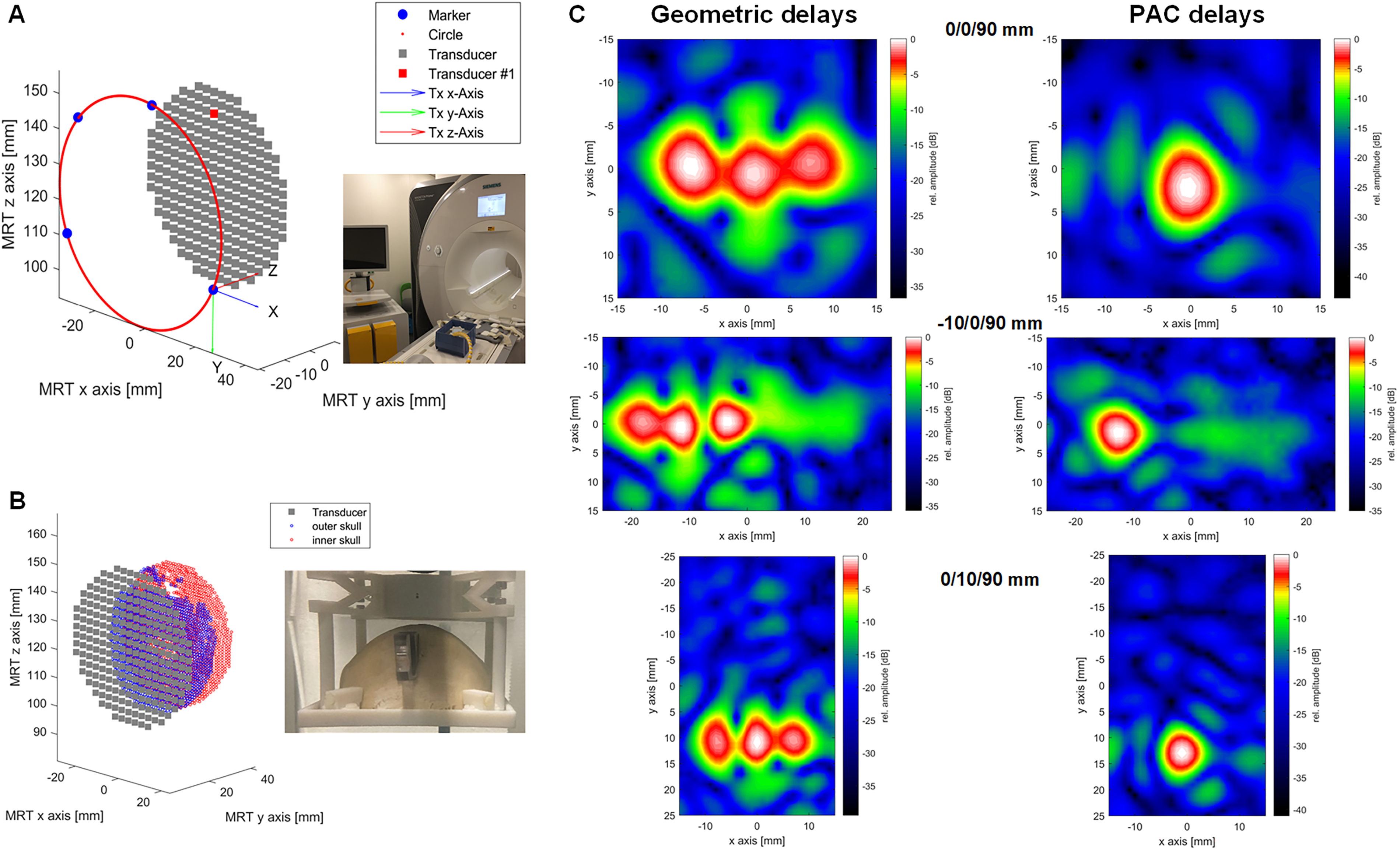
Proof of concept of phase aberration correction (PAC) in the MR-guided setup.
Impact of Using Phase Aberration Correction Delays Versus Geometric Delays on Different Pressure Distribution Field Metrics When Sonicating Through the Ex Vivo Skull
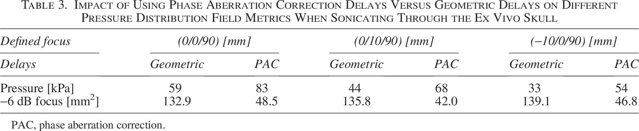
PAC, phase aberration correction.
We furthermore investigated the computation time of the PAC algorithm. In our partially parallelized implementation, the calculation of the delays for a defined targeting scenario took between 20 sec (for a 1-mm point grid on the skull) and 284 sec (for a 0.5 mm grid) on a commercial PC (Intel Xeon W-2235, 3.8 GHz, NVIDIA RTX A4000).
Preliminary assessment of MR useability
Different experiments have been performed in view of a first assessment of the MR compatibility of our multichannel system. Figure 10F,G shows the results of the magnetic for deflection measurement according to ASTM F2052. No measurable mechanical attraction force to the bore at the location where the components are used could be detected. Next, we investigated if susceptibility artifacts might have a detrimental effect on MR imaging, especially for close to surface ROIs. Figure 10D,E shows MR images of the probe immersed in the CuSO4 solution acquired with two different sequences. The images show that there are no susceptibility artifacts directly under the transducer aperture. Accordingly, even brain areas very shallow under the skull can be imaged in the presence of the probe such that MR can be considered as a valuable tool for not only planning but also monitoring of ultrasound neurostimulation with the presented transducers.
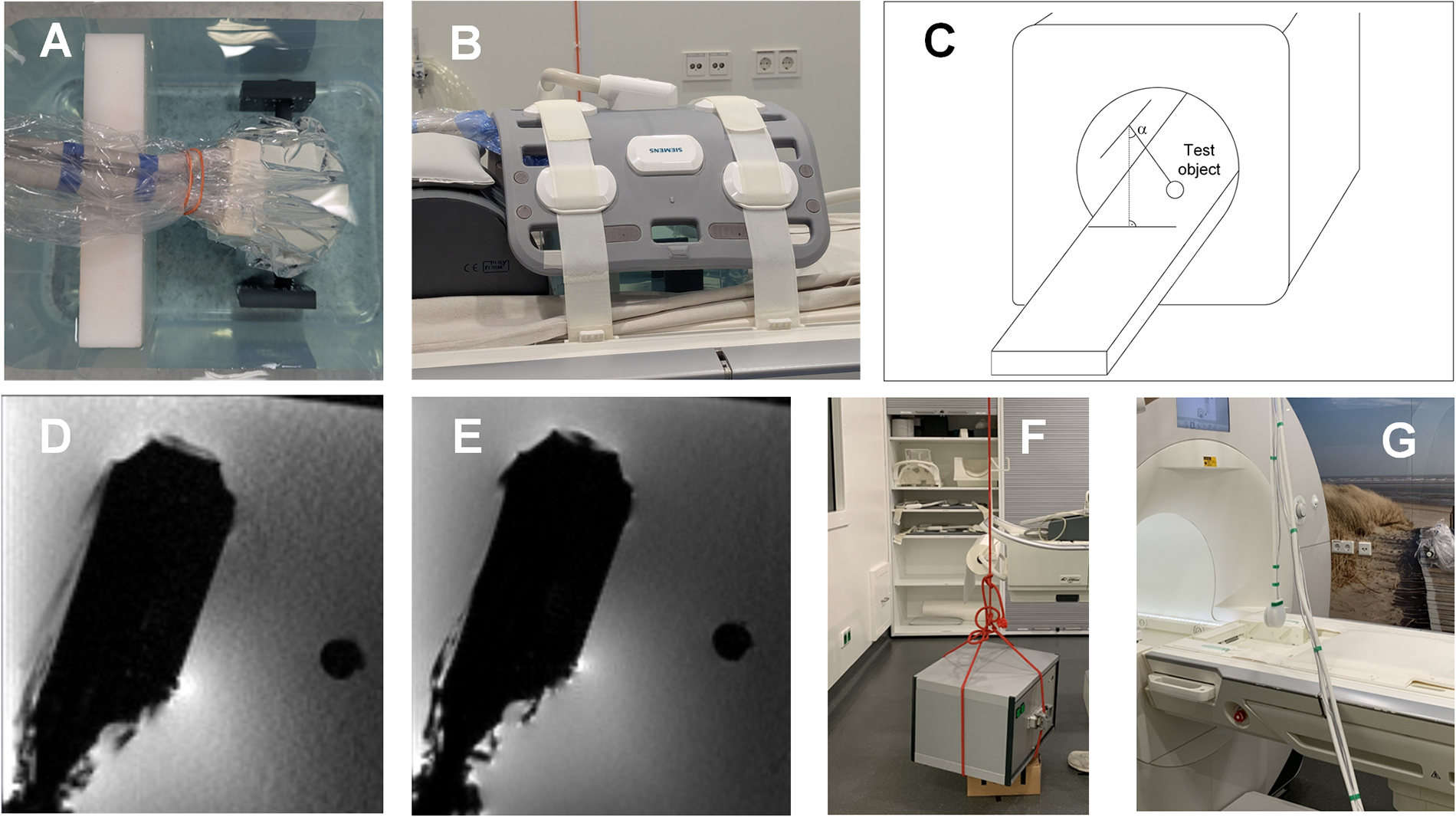
Assessment of MR susceptibility artifacts.
Next, we investigated the ability to localize the acoustic focus position with MR-ARFI. Figure 11 shows representative acoustic radiation force value (t-score) in a CIRS phantom at a slice where the maximum was found during nonsteering condition (panel A). Panels B and C show the ultrasound focus on the same image slice while the beam was moved in y-direction at 7.1° and 14°, respectively. This demonstrates the feasibility of MR-ARFI as a confirmation approach for targeting deep regions in the medium for therapeutics focused ultrasound applications with our system.
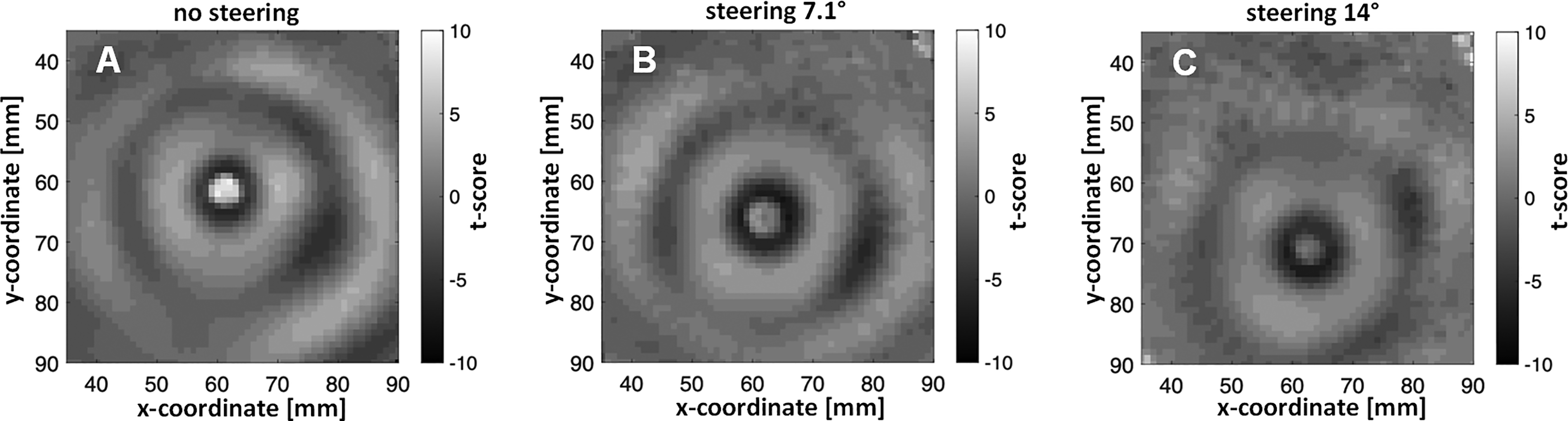
Proof of concept of MR-ARFI by tracking the change of the focus position.
Safety assessment
The system was characterized by the accredited testing laboratories TUEV Süd (Munich, Germany) and CTC Advanced GmbH (Saarbrücken, Germany) for compliance with acoustic safety (IEC 60601-2-37: 2024, 2024) and electrical safety, respectively (IEC 60601-1:2005+A1:2012+A2:2020, 2021). The electrical safety testing included assessment of leakage currents or of the dielectric strength of insulating materials (e.g., coupling layer of the ultrasound transducer) against test voltages of up to 4 kV. The report confirms that the electronics and the transducer comply with the tested requirements of IEC 60601–1:2005.
Discussion
We presented a new multichannel system for 3D ultrasound neuromodulation with a flexible architecture optimized for being usable in a wide range of brain research applications. We demonstrated the capabilities for 3D beam steering in a range of ±20° and a lateral focus size down to less than 4 mm (depending on focus depth), which is less than the size of a human gyrus. Our assessment of the steering capabilities has shown that significant grating lobes appear at steering angles larger than 20°. Accordingly, to prevent sonication of structures other than the ones which are actually targeted, the steering angle is limited to 20° in the system’s software. The hardware and the UI allow easy definition of customized stimulation sequences on different levels (definition of pulse length, pulse train, and pulse train repetition). A flexible pad ensures easy coupling to the skull, even at locations with significant curvature. Different software control options (full integration into a third-party application using an SDK, MR-guided workflow, neuronavigation workflow) allow to adapt to the preferred clinical workflow. In addition, the safety has been assessed by an accredited laboratory for an easy transfer into clinical application. In particular, compliance with the electrical safety standard IEC 60601–1 has been testified. When it comes to acoustic safety, since the standard aims at diagnostic devices, the acoustic output has shown to be potentially above the defined threshold. However, the purpose of the testing was to identify for which settings (voltage, focus depth, temporal pattern) the system can safely be driven within the limits (in terms of ISPPA, ISPTA, MI) defined for clinical LIFU applications (Martin et al., 2024b). The outcomes of the accredited measurements were used to calibrate the transducer output when planning a sonication scenario (for instance, when using k-plan). When no commercial planning tool is used, the system can be used in two control modes. In a so-called clinical mode, the output values (ISPTA, MI) are either limited by the software to 720 mW/cm2 and 1.9, respectively. In addition, a “research mode” to be used in phantom studies giving full access to the signal parameterization while disregarding the limitations of IEC 60601–2–37 has been implemented.
For compensation of the significant aberration resulting of the propagation through the skull, a PAC algorithm has been integrated. Preliminary data acquired on an ex vivo skull shows that the widening of the focus after propagation through the skull can be corrected and that the pressure can be increased by applying the PAC algorithm (Fig. 9). For safety reasons, the PAC effect is limited to the correction of the applied phases, and no amplitude correction has been implemented so far. With the integrated MR fiducials, the transducer can easily be localized in the MR data coordinate system, which is a prerequisite for PAC. The compatibility to neuronavigation systems allows potentially limiting the MR use to a single initial scan. The precise control of individual delays not only allows integration of other PAC approaches beyond the one implemented into the system but also enables rapid readjusting of the 3D focus position for customized spatiotemporal stimulation.
When it comes to limitations of the system, the elongated axial focus must be mentioned. This is an intrinsic limitation of single element or 2D matrix array probes and is more pronounced the farther the focus is away from the aperture. It can however be overcome using more than one transducer in a cross-beam setup (Ilham and Kiani, 2023; Naftchi-Ardebili et al., 2024), which is supported by the hardware and is the subject of current studies. Furthermore, a more detailed validation of the implemented PAC algorithm could be performed. In our experiments, the correct refocusing using our algorithm could be demonstrated on an in vivo skull phantom. However, a validation on a more diverse dataset (different skull shapes and thicknesses) would be desirable.
Conclusions
In summary, a new versatile ultrasound neuromodulation platform was developed and characterized. It represents a compromise between conformal helmet-like systems (with high complexity and challenging acoustic coupling) and single element transducer setups (needing repositioning of the transducer for reaching a different target and preventing the use of PAC approaches). It is flexible in terms of spatiotemporal stimulation patterns and can be accommodated to different workflows. Calibration and testing by accredited safety laboratories have paved the way toward clinical use of the device, so that it can contribute to accelerating the research of ultrasound as a therapeutic tool for a large range of brain conditions.
Authors’ Contributions
S.H.T.: Conceptualization (lead); data curation; formal analysis (lead); funding acquisition (lead); investigation (lead); methodology (lead); project administration (lead); resources (lead); supervision; validation (lead); visualization; writing—original draft; and writing—review and editing (lead). M.F.: Conceptualization; data curation (lead); formal analysis (lead); investigation; methodology (lead); validation (lead); visualization (lead); writing—original draft: (lead); and writing—review and editing (lead). C.R.: Conceptualization; data curation (supporting); formal analysis; investigation; methodology; software; validation; writing—original draft; and writing—review and editing. H.H.: Conceptualization; data curation (supporting); formal analysis (supporting); methodology; software (lead); validation; writing—original draft; and writing—review and editing. C.D.: Conceptualization; data curation (supporting); formal analysis; investigation; methodology; validation; writing—original draft; and writing—review and editing. W.B.: Conceptualization; data curation; formal analysis; investigation; methodology; software; validation; visualization; writing—original draft; and writing—review and editing. P.W.: Data curation; formal analysis (supporting); investigation; software; validation; and writing—review and editing. M.M.: Data curation; formal analysis; investigation; software; validation; writing—original draft; and writing—review and editing. G.H.G.: Formal analysis (supporting); investigation; methodology; software; and writing—review and editing. K.B.P.: Funding acquisition; methodology; project administration (supporting); resources; and writing—review and editing. A.M.: Funding acquisition; methodology; project administration; resources; supervision (lead); and writing—review and editing.
Footnotes
Acknowledgments
The authors thank JW Jenne, Fraunhofer MEVIS, Bremen, Germany and TA Kuder, German Cancer Research Center (DKFZ), Heidelberg, Germany for the MR measurements. The authors also want to thank medical faculty of the Saarland University for providing the skull samples.
Author Disclosure Statement
The authors declare no conflict of interest.
Funding Information
The development of the first generation of the FUS system was funded by MRI Instruments Inc., Minneapolis, MN, USA. Further funding was provided by the Fraunhofer-Gesellschaft in the context of the project THERANUS (840232), by the German BMBF under the projects 3MP-FUS (13GW0619C) and EUPHEMIA (01GQ2102), by JPND and BMBF under REMOPD (01ED2105A), and by NIH (R01 EB032743).