
Abstract
This article explores four key methodologies for measuring historical musical instruments in preparation for 3D printing: manual measurement, flatbed scanning, light-based 3D scanning methods, and computed tomography (CT) scanning. Each method offers distinct advantages in capturing the structural details and limitations of delicate artifacts. Manual measurement remains indispensable for tactile feedback and verifying relative distances, particularly when digital methods fall short. Flatbed scanning offers high lateral resolution yet struggles with depth accuracy and modern technological support. 3D scanning technology excels in surface precision and avoids reflection issues but can be affected by material properties such as translucence. CT scanning provides exceptional internal visualization but faces challenges with material density artifacts and resolution constraints. By integrating these approaches, researchers can create accurate and interpretable 3D models that balance historical fidelity with modern analytical precision. This interdisciplinary workflow enhances the preservation and understanding of historical instruments, enabling new insights into their craftsmanship and design.
Keywords
Introduction
The digitization and reconstruction of historical musical instruments for research, preservation, and replication have gained significant attention in recent years. With advancements in technology, several methods are now available to measure and analyze these instruments in preparation for 3D printing. This article examines four key methodologies: manual measurement, flatbed scanning, 3D scanning, and computed tomography (CT) scanning. Each technique offers distinct advantages and limitations, and their integration provides valuable insights into the intricate designs of historical instruments.
Measurements taken from original instruments have been classified into two different kinds of data. The first category comprises dimensions directly affecting acoustic properties, specifically the bore profile, fingerhole sizes, positions and depths, and all other sound-producing attributes, and these measurements are obtained and reported as objectively as possible. The second kind is for the external profile of the instrument with the focus on aesthetic implications. For these, direct measurements of the design of the instrument will also be compared with 2D scans and photos. The measurement phase is kept strictly separate from attempts to reconstruct the original artisan's design ethos or to introduce the observer's interpretative bias; it is exclusively concerned with objectively documenting the instrument's current state. Minimal interpretations of raw measurement data are advocated to preserve its inherent objectivity. However, variability in results persists due to inherent material disparities and the nuanced adjustments made by individual artisans. Consequently, data analyses across multiple datasets can illuminate the tolerance patterns specific to individual makers or workshops, thereby facilitating insights into design evolution or experimental variations.
In order to account for the accuracy of measurements on historical instruments, one must address both material-specific and environmental variables. Wood and ivory, being softer than metal, will deform if excessive force is applied; in this practice, minimal pressure is essential and highly subjective to the researcher conducting the measurement. Makers of woodwind instruments routinely remove material both internally and externally over several years before final assembly, allowing the wood to shrink and stabilize between stages of material removal (Ormiston & SWNS Media Group, 2020). Subsequent fluctuations in temperature and moisture induce further dimensional change. This is especially evident in smaller collections without climatological regulation: measurements taken on consecutive days of differing weather may therefore diverge. Parts such as cracked sockets, common in historical woodwind instruments, defy precise gauging by all methods mentioned and must instead be assessed by informed judgment guided by experience or comparison with other samples, for instance parts from the same maker. Surface quality varies markedly between dense tropical hardwood and softer local fruitwood; the intersection zones of successive reamers often retain micro-voids untouched by either tool. Some accumulations arising immediately after the making process, such as residual wood chips from drilling the finger-holes, and those developing over time, including dust, smoke particulates, oxidized bore oil, and general debris, can obscure the true dimensions. Time constraints imposed by museum opening hours, staff availability, and the need to coordinate with conservators or curators limit opportunities for repeated measurement, calibration, and environmental logging, so researchers must balance thoroughness against access restrictions. High-precision measuring equipment, such as metal callipers or ball-bore gauges, are frequently prohibited in collections to avoid inadvertent damage, compelling use of lower-precision alternatives such as carbon-fiber callipers and heightening overall measurement uncertainty. Taken together, a measurement should be regarded as reliable only if the data can be obtained with as much repeatability as possible. Where direct precision is not consistently achievable, the effective resolution may vary substantially due to the factors outlined above. In cases of ambiguity, researchers should combine their best possible readings with informed judgment and decision-making.
Although the sophisticated measuring equipment can display an accuracy of 0.01 mm, in practice numerical values are rounded to the nearest 0.1 mm when they are brought to the CAD drawings, unless critical sections necessitate more precision. Such drawings serve primarily as interpretative guides rather than exhaustive blueprints, facilitating both the recreation of the instrument and comparative analyses among similar artifacts. Furthermore, the distinctive stylistic nuances embedded within these drawings reflect the individuality and expertise of their creators. While some artisans, such as Fred Morgan (Morgan, 1982) and Jean-Francois Beaudin (Dobbs, 2012), adopt a more illustrative approach reminiscent of sketches, others like Mike Nelson (Nelson, 1999) and Simon Hope, with engineering backgrounds, adhere to the style of engineering blueprints.
Manual Measurement: Tradition Meets Innovation
Manual measurement, a centuries-old practice, continues to play a vital role in instrument analysis. It is a practice routinely carried out by instrument makers on a daily basis as part of quality assurance. As the simplest method discussed in this paper, physical measuring can be carried out with a single researcher and can be optimized with two, one taking the measurements while the other writes them down. The collaboration can save time, since museum opportunities are usually time-limited.
In the context of contemporary oboe-making within a small to medium workshop environment, exemplified by Howarth of London, a specialized measuring instrument is used for the assessment of the bore. Following the processes of gun-drilling and reaming, the luthier meticulously examines the bore using circular steel probes to ascertain its diameter at specific depths. Noteworthy is the distinctive disparity between the characteristics of a recently drilled bore and that of a historical instrument or indeed a reproduction where preliminary boring has taken place and the instrument awaits final finishing. In every case, some deformation of a perfectly circular bore is inevitable. Environmental conditions continue to be relevant, causing further possible changes. This evolution introduces complexities in the field of measurement, requiring an adaptive approach to accurately gauge the dimensions of historical bores (Drescher et al., 2020). The introduction of finger-holes and other apertures, meticulously drilled into the chanter, further compounds the intricate nature of bore deformation. These intentional modifications, while serving functional purposes in the instrument's design, cause alterations in the structural stability of the chanter. The consequential deformation manifests as an elliptical configuration when observed in cross-section, deviating from the original circular form. This transformation poses a significant challenge to the conventional circular probes used for inspecting newly created bores. However, those circular probes cannot be used to examine bores in historical wind instruments. This necessitated the use of a differently shaped probe. Recognizing this deviation from circularity, the tip of the measuring tool I have designed has undergone adaptation. Specifically, the tip now assumes an elliptical shape, characterized by a significantly shorter minor axis, strategically designed to avoid contact with the bore along its minor axis. This nuanced adjustment ensures accurate measurement of the modified bore configuration. In the process of measurement, the insertion of the rod and measuring tool heads into historical instruments necessitates careful consideration of material compatibility taking into account any potential for causing internal scratching. To this end, the selection of materials for the measuring tool becomes a critical aspect, requiring attributes such as lightness, softness, durability, and non-reactivity.

Two different probes made from PA2200.
This research contributed to the development of a novel method for fabricating probes. In this instance, these probes are design for measuring British Isles bagpipes and concert flutes. New probes are made from PA2200, a type of bio-compatible nylon. It has several commendable qualities and is formed by the SLS (selected laser sintering) technique. The new probes have been designed by the author and produced in STL (stereolithography) format. They can be manufactured by any SLS printing service. The exact dimensions of the probes are not critical to the printing process, as the measurement readings were applied and marked after post-production procedures such as edge removal and polishing. Notably, its non-reactive properties make it an ideal choice, as it does not elicit adverse reactions with materials commonly found in historical instruments, including bone, ivory, wood, and metal. This non-reactive nature assumes particular significance in conservation efforts, as it serves to minimize the risk of chemical interactions that could potentially compromise or alter the composition of historical artifacts. Its inherent rigidity proves advantageous in the construction of measuring tools designed for direct contact with delicate collection materials. This structural stability ensures precision and accuracy in measurements without compromising the integrity of the artifacts. The soft surface characteristic is a desirable attribute in applications involving direct contact with sensitive materials, acting as a protective barrier against scratches and abrasions during the measurement process. The combination of non-reactivity, rigidity, longevity, and a soft surface renders it a suitable and reliable material for crafting measuring tools in conservation work. This choice ensures the meticulous preservation of historical items, reflecting a commitment to care and precision in the conservation process. Its longevity emerges as a key attribute, contributing to the durability of conservation tools. This robust quality extends the functional lifespan of measuring instruments, mitigating the need for frequent replacements and offering a cost-effective solution to the challenges of conservation work (Yao et al., 2020).
The aspect of portability is paramount in the design and functionality of the measuring tool, making its use convenient in diverse settings, including distant museums. To enhance portability, the measuring tool has a modular design. Both probes and the handle shaft can be easily separated, facilitating convenient storage and transportation. The smaller heads, resembling long rods with a length of 200 mm, can be detached from the main structure, while the larger heads, taking the form of disks, are stowed in a compact container. This modular configuration not only streamlines the tool's footprint but also ensures that it adheres to the stringent size limitations when traveling, particularly considering the confined dimensions of cabin baggage, restricted to 400 mm in the largest dimension. The handle shaft, a central component in the measuring tool's structure, is designed with a length of 300 mm. This length is chosen to accommodate the average size of the chanter of all common British Isles conical bagpipes (Great Highland Bagpipes, Border pipes, Union pipes, and Pastoral pipes), which typically ranges between 320–400 mm. The tool's overall length, inclusive of the handle and additional length required for precise readings, surpasses that of the entire chanter. The probes are affixed to the shaft through a secure screw-mounting mechanism, ensuring stability during measurements.
Measurement inaccuracies are attributable to different factors, including measuring tool design and human error. This observation is not confined solely to the present measuring apparatus but extends universally across various measurement tools and techniques. Specifically, thickness gauges, designed to ascertain the distance between two surfaces, introduce variations contingent upon the frictional dynamics and material deformations induced by applied force. Furthermore, the intrinsic limitations of manual measurements arise from subjective human interpretations rather than systematic evaluations of tolerance disparities. In the realm of measurement methodologies, systematic errors can arise in successive stages, each contributing incrementally to the overall error margin. One such instance is observed when the tool head touches the bore. Specifically, the dimension of probes is inherently smaller than the bore's diameter. From a mechanical engineering perspective, the free running tolerance (the tolerance for sliding action in engineering, those standards such as H9/d9 in this case, for S7 to T24, which suggests that S7 is between 7.00 mm and 7.036 mm for H9, 6.924 mm and 6.960 mm for d9, T24 between 24.000 mm and 24.052 mm for H9, 23.883 mm and 23.935 mm for d9, this is the ISO system for limits and fits) (International Standard & ISO/TC 213, 2010) stands between 0.112–0.169 mm. This threshold goes beyond the tool's measurement tolerance, making it necessary to add a compensatory mechanism to account for this unavoidable systematic error. An asymmetrical distribution of tolerance discrepancies is occasionally observed, exemplified by the potential overestimation in the depth readings of the probe relative to the distance between the section area and the chanter's end. Both the maximum and minimum readings in bore sections may deviate from the section’s longitudinal axis, as the probes primarily ascertain the deepest and shallowest depths attainable within the bore, respectively (Bouterse, 2015). The diameter readings will always be larger than the actual dimensions of the measured object. This deserves comparison with the use of callipers for measurement, since the force applied when holding the claws can deform both the object and the callipers. Whether a gentle or strong squeeze is applied, it will result in varying measurements bigger or smaller. The depth information can also introduce errors. This can be attributed to the occasional misalignment of the measuring rod with the chanter bore's central axis. But the deviation arising from the tilting of the instrument's stick remains minimal; for instance, a rudimentary calculation demonstrates that a 3-degree tilt across a bore spanning 400 mm results in a variation of merely 0.15 mm—in the range of the minimum unit of depth measurement. Should the tool permit, the minimum unit, such as the 0.01 mm resolution of callipers or the 0.005 mm capacity of certain thickness gauges, becomes the documented value. Notably, the precision achieved during the instrument-making process rarely matches that of initial measurements, as changes continue to occur during the instrument-making processes. Voicing and subtle adjustments are typically reserved for the final stages rather than addressed earlier in the process. As elucidated by Eric Moulder, an esteemed maker of historical woodwind instruments, the historical contexts often lacked sophisticated measurement tools, yet achieved micron-level precision in reed making through subjective human techniques, such as assessing translucency under a light source or gauging flexibility by finger pressure (Moulder, 2020).
Flatbed Scanning: A Traditional Yet Effective Approach
Flatbed scanning, though an older technology, remains a viable option for measuring certain aspects of historical instruments. Examples of scans obtained with this method can be found in the archive of Na Píobairí Uilleann, the Irish Pipers’ Society (Haneman et al., 2013). There are many methods available for scanning 2D objects, but fewer techniques are effective for converting 3D items into 2D projections. Document scanning often requires feeding the item into a mechanical system, such as drum scanners or “mobile” scanners, to achieve optimal results, which is not suitable for 3D objects. The flatbed scanning method was chosen for its ability to safely accommodate 3D objects placed on top of the glass surface. However, not all common scanners are suitable for this purpose and those employing the charge-coupled device (CCD) principle provide better success. Contact image sensors (CIS) represent a more recent, cost-effective method, with the advantages of lower power consumption and more compact designs; however, CIS scanners lack depth of field, making them unsuitable for accurately projecting 3D objects. In contrast, CCD scanners preserve depth information. A decent quality CCD scanner can easily achieve 1200 dpi, with a resolution of 0.021 mm, significantly surpassing 3D scanning and CT scanning at a distance. This high resolution ensures that the portions of the object in direct contact with the glass are captured with exceptional clarity and accuracy (Walker, 2012). Object scaling can be facilitated by including a reference scale within the scanned frame, allowing for later calibration during the modeling process. However, due to the three-dimensional nature of objects, depth variations on the scanner result in distortions similar to those caused by cameras. One of the key advantages of flatbed scanners is their ability to project curves and irregular shapes onto the image, which can then be traced using Bézier curves. This technique can be combined with other methods, such as molding the bell of a Baroque musette grand chalumeau or scanning a sacrificial piece with finished finger-holes sliced in half, to capture real-world undercuts. For instance, in the case of woodwind instruments turned on a lathe, lateral readings are precise, but longitudinal measurements tend to be less accurate. Additionally, metal reflections can introduce artifacts such as auras, complicating the image analysis. Despite these limitations, flatbed scanners remain far more portable and cheaper than 3D scanning and CT scanning technologies.
The procedure for using a flatbed scanner begins by calibrating the exposure level to achieve neutral color tones. The goal is to prevent overexposure of ivory or bone parts while maintaining clear definition of darker materials, such as ebony or cocus wood, ensuring that features like stamps remain readable. Test scans are conducted at low resolution but cover the full flatbed, allowing for rapid assessments. If a particular side of the object does not contain crucial information, the resolution can be set higher (600 dpi or more), which is sufficient for tracing in CAD software. For objects with important side details, the positioning is critical, as longitudinal accuracy diminishes with excessive rotation. Aligning features, such as finger-holes, with the scanning plane may require multiple attempts to achieve a satisfactory result. Once the alignment is correct, the dpi setting can be increased for the final scan. It is advisable to save the images in TIFF format, rather than PNG or JPEG, as TIFF retains a larger dynamic range and more color information, allowing for more effective exposure adjustment and color correction without introducing artifacts.

A scan of a tenor drone top of a set of Border pipes from Morpeth Chantry Bagpipes Museum [MOPBM 044].
The approach in this paper is that 2D scans serve as excellent templates for annotating measurements obtained through manual measuring methods. When conducting a two-day measurement schedule, all objects are scanned at the end of the first day, and the scans are processed outside of museum hours to prepare for further measurements on the second day. Post-processing often involves converting the image to greyscale for enhanced readability and printability. This not only accelerates the process compared to the manual method, which involves documenting all longitudinal readings and fewer lateral ones, but also enhances accuracy due to the way callipers function. With callipers, only three types of measurements can be directly obtained, and representing concave shapes proves to be particularly challenging.
When scanning procedures are intended for documents, most flatbed scanners are considered to be far too slow, and consequently overhead scanners are commonly used. However such devices are unsuitable for scanning instruments and in such cases the CCD scanner remains the preferred device. The imaging component of the consumer-level overhead scanner is typically a webcam attached to the top of the arm. The image is processed by the built-in algorithms for page correction. However, the algorithm is designed solely for correcting 2D planes. Some higher-end overhead scanners which can be found in archives and libraries are equipped with CCD sensors, but the built-in algorithms limit the versatility of these machines.
In contrast, these flatbed scanners require no specialized knowledge, software, or hardware, and the computing power needed for scanning and processing is modest—any modern laptop is sufficient. Additionally, no consumables are used during operation. However, it is worth noting that long-term support for these scanners is limited, as software updates have been discontinued in recent system versions. Although technical support for many such scanners has long ceased, it is usually possible to find second-hand examples in good condition.
Light-Based Scanning System for Precision Measurement
These sophisticated techniques such as photogrammetry and structured light are rapidly developing, although at present their usefulness in examining woodwind instruments is limited. What is required to make them more useful is greater capability in highly polished surface combined with highly contrasted color parts, such as ebony with ivory, as well as reflective metal ferrules. The challenge of scanning also stems from the size and shape of the objects. While the resolution advertised by manufacturers is significantly higher than the dimensions of the instrument parts, capturing the intricate details of the instruments remains exceptionally difficult. The tracking ability of these systems remains limited when dealing with rotationally symmetrical objects or sections with nearly identical features, such as combs and beads.

A light-based 3D scan displayed alongside a CAD model [MIMEd 1491].
Despite all the advances, all visible light scanners are only capable of measuring external surfaces. While light can penetrate some holes, access to internal structures is limited and inconsistent. If a hole is large enough, such as the embouchure of a flute head joint, multiple passes of scans may be able to capture the undercut with sufficient accuracy for modeling. However, the transitional edge between the bottom of the hole and the bore is often poorly represented, as the shallow angle between the two surfaces makes it difficult to capture from any direction, whether along or across the main bore. Visible light scanners also struggle to accurately scan dovetail undercuts like V slots or any features that are not directly visible such as T slots. This light-based scanning process shares a challenge with CNC milling: objects must be held in place firmly during scanning, which means at least one section of the object is obscured or covered by mounting devices such as clamps or vices. Structured light and similar technologies use multi-line structured light stripes to capture surface information. When parallel light hits the surface, it deforms. This deformation is captured by imaging or laser sensors to calculate the distance between the light source and the object. During the reconstruction process, the scanning software is capable of stitching different scan passes together, a process that requires human input to align sections using at least three points of reference. However, this remains challenging with plain, tapering shapes such as the back of a chanter or the top of a Pastoral or Border pipes drone. Reflection issues can be mitigated with the use of 3D scanning spray, which applies a coating of 8–15 microns that evaporates within a few hours, leaving no residue. This method is widely accepted in the industrial and 3D printing communities but has yet to gain acceptance among museum conservators as it has not been scientifically tested within conservation workflows. They remain concerned that residue from the process could permanently affect the instrument. The use of such scanners has limitations in tracing objects with plain textures and rotational symmetry. Some scanners come with black-and-white dot stickers that, when adhered to the object, create trackable features. Another technique involves applying simple moldable products to create height variations, but neither of these methods is suitable for use in museums. While a coordinate system can significantly improve tracking, the necessary toolkits are expensive.
Here are two examples of coordinate-measuring machines (CMM) which are portable, easy-to-set-up systems that can be used on-site in museums and collections. Both systems are under evaluation in the Heritage Collections at the University of Edinburgh.
Photogrammetry Method
The Arago photogrammetry rig is a specialized imaging system designed for capturing highly detailed 3D models of objects by Rigsters, Denmark (Rigsters, 2020). It employs a Digital Single-Lens Reflex (DSLR) camera, which is mounted on a motorized, numerically controlled rail system, while the object is positioned on a turntable. This setup allows for a fully automated process, where the system's accompanying software handles all adjustments, including focus, exposure, and movement, reducing the need for manual intervention. It is portable, but the rig's significant weight and the space required for operation make it difficult to accommodate in smaller museum research rooms. The quality of the scans produced by the system largely depends on the resolution and quality of both the camera and lens. Higher-resolution cameras with precision lenses yield finer details, crucial for accurate 3D reconstructions. However, a notable limitation of the system arises from the performance of the turntable. Although designed for smooth rotation, it can exhibit instability compared to the precision turntables used in CT scanners. This instability introduces minor displacements that can affect the accuracy of the final scans, as the system may prioritize tracking the fiducial marks (visual tracking marks) on the turntable rather than focusing precisely on the object's features. One advantage of the photogrammetry process is its ability to generate a UV map (a texture mapping technique which captures the surface textures and colors) and a height map (also a texture mapping technique which records elevation details). While these outputs are valuable for visual representation and some forms of analysis, their usefulness for detailed object reconstruction is more limited. Photogrammetry, despite its strengths in capturing surface details, lacks the penetrative depth of scanning techniques like CT or laser scanning, which can capture internal structures. Thus, for researchers focused on internal details or complex reconstructions, photogrammetry may offer only a partial solution.
Coordinate-Measuring Machine
This versatile 3D measurement system offers two primary methods of data acquisition: contact measurement and non-contact measurement. Contact measurement is performed using interchangeable probe attachments that come in a variety of materials, lengths, and sizes, allowing for customized scanning depending on the object being measured. According to the manufacturer, FARO (FARO, 2021), contact measurement offers higher precision and greater detail than non-contact methods, as it physically touches the object's surface, ensuring direct feedback about its geometry. However, the arm's considerable weight and the critical importance of stabilizing the base pose challenges, particularly in environments such as museum research spaces. Any movement or instability in the arm's base during scanning can introduce significant errors, potentially compromising the accuracy of the data collected. Non-contact, light-based measurement, on the other hand, uses a technology similar to structured light to capture the object's surface without physical contact. This method introduces less errors by physical movement of the system, but it remains limited in its ability to capture complete models from multiple orientations within a single scan pass. The FARO's CAM2 software, while sophisticated, restricts scanning to one orientation at a time, meaning that to capture the full geometry of an object, multiple scans from different angles must be taken and stitched together manually. This can be very cumbersome in museum environments where the opportunities for examining items are often limited in terms of time and space. A unique advantage of the FaroArm system is its ability to rescan an object and directly compare the newly captured data with the previously generated CAD model using the CAM2 software. This feature facilitates easy and accurate comparisons between the physical object and its digital model, which is invaluable for verifying measurements and detecting wood deformation, such as warping or bending in boxwood. The deformation is very hard to measure from physical or 2D scanning. However, the RevEng software, another tool in the FARO suite, allows for stitching multiple scan passes but lacks the capability for CAD comparison or direct export of raw models, which limits its utility for some advanced workflows. All scans produced by the FaroArm are saved as point clouds, collections of data points representing the object's surface. The density of these point clouds is influenced by several factors, including the speed at which the arm moves during scanning, the reflectivity of the material being scanned, and the distance between the scanner and the object. One of the challenges faced by this system is the difficulty of scanning translucent materials, such as ivory, which is often found in historical instruments. Translucent materials allow light to pass through, which can distort the captured data.
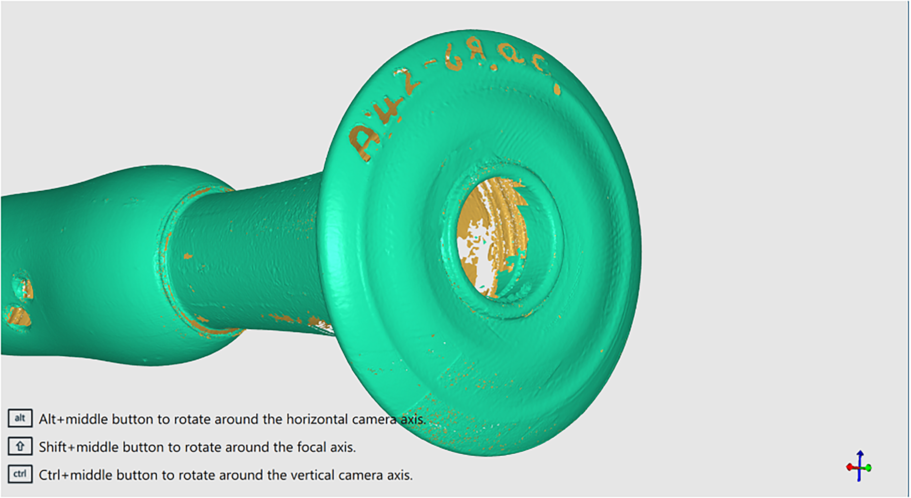
A scan from the FaroArm of a musette bell with accession numbers [MIMEd 2838].
In the case of ivory, this effect can cause the appearance of Schreger lines (the natural visual artifacts seen in ivory cross-sections) to be inaccurately recorded on the surface texture of the 3D model, even if these lines are not visible on the outer surface textually. Additionally, museum accession numbers coated in clear lacquer can absorb light, creating voids or “holes” in the scan data that distort the final model. While the FaroArm system remains proprietary, it offers flexibility through the ability to export point cloud data, which can be imported into third-party open-source software for further processing. This flexibility ensures that users are not entirely dependent on FARO's software ecosystem. Although the system's cost is currently high, prices are expected to decrease as the technology matures and becomes more widespread. The system also requires a significant investment in computing power, especially in terms of a high-performance graphics card, to handle the large data sets generated by the scans. Despite this, the learning curve for operating the FaroArm is relatively short, and the system's efficiency is further enhanced by the fact that it does not require consumables during the scanning process, making it cost-effective for long-term use. In conclusion, it is worth remarking that although such techniques show great promise in expanding the opportunities for the extremely detailed examination of woodwind instrument, further development will be necessary to make them fully useful.
The Role of Micro-CT Scanning in Instrument Analysis
Computed tomography (CT) scanning is a powerful tool for examining the internal and external structures of historical instruments. The application of micro-CT imaging in the examination of historical musical instruments necessitates a collaborative effort among museum curators, conservators, and imaging professionals. This interdisciplinary approach, while promising, presents challenges that merit critical examination, particularly in the context of the potential drawbacks associated with the technique. The reality of effective communication and shared understanding becomes paramount for aligning imaging goals with research objectives. Despite the interdisciplinary nature of these collaborations, the seamless integration of varied backgrounds remains a complex undertaking.

Two x-ray images of the Boîte and Pavillon of a Baroque musette [Private Collection, London].
Despite the remarkable high-resolution capabilities inherent in CT scans, the imaging process encounters several challenges, particularly when applied to the intricate composition of woodwind instruments. Woodwind instruments, distinguished by their composite structure comprising materials like tropical hardwood or local fruitwood as the main body, metal keys and ferrules, and ivory mounts, present a distinctive challenge during CT scanning. One complex challenge arises when dealing with mixed-density materials with automatic exposure levels (Plath, 2022). Such difficulties were encountered during an investigation of an ivory recorder as referenced below, in a project at the Pitt Rivers Museum, Oxford, the cedar block resulted in a convolution of data fibers. The pronounced disparity in absorption rates between ivory and cedar introduces complexities in capturing clear and distinct images (Walters et al., 2018).

The artifact of dark band and metal reflection from a metal ring of a flute foot joint [Private Collection, Norwich].
Metal components can generate reflections that interfere with the accuracy of the scans. These reflections manifest as bright streaks or noise, obscuring details and compromising the overall image quality (Chadwick et al., 2016).
Since high-density materials absorb and retain the energy of X-rays to a far greater degree than lower-density materials, this results in artifacts such as shadows or dark bands (Hammersberg & Mångård, 1998). Researchers address this challenge by employing dual-energy CT techniques and material-specific imaging algorithms. These strategies aim to effectively differentiate materials, mitigating artifacts, and enhancing the precision of 3D reconstructions.

A 3D model generated from CT scan data, showing artifacts [Private Collection, Norwich].
Throughout the scanning process, where images are captured in layers and subsequently stacked to form the 3D model, challenges arise in the form of layer artifacts. Misalignments or inconsistencies between adjacent layers introduce irregularities and discontinuities, compromising the overall smoothness and structural integrity of the 3D representation. To alleviate layer artifacts, precise calibration of the scanning equipment and meticulous alignment of images are essential. Although post-processing techniques, such as interpolation and smoothing algorithms, can be employed to reduce discrepancies, their application introduces interpretational challenges that may impact the accurate representation of the data.
The mechanical vibrations induced by the object rotating pose a significant challenge to the quality of CT scans, particularly when capturing the intricate details of historical woodwind instruments. Although the turntable is designed to be more steady and slower than the one previously mentioned in the Arago system, these vibrations can still manifest if the object is not firmly mounted. Such vibrations generate blurring effects in the captured images, particularly in fine details, thereby compromising the quality of the scan. Furthermore, dampening techniques and vibration isolation methods, such as the use of deli cups (a portioned disposable plastic container which is commonly used in commercial kitchens) with cotton wool for holding small pieces and 3D-printed mounts for larger instrument sections, are implemented. These bespoke solutions offer a softer and more secure support structure than standard sample holders, which are often too sharp or hard for historical instruments.

A comparison of the undercut on a Northumbrian small-pipes chanter between a 3D model generated from CT scan data and a CAD model developed from 2D technical drawings and measurements obtained by complementary methods. [Private Collection, London].
The operational constraints of standard micro-CT scanners, exemplified by models such as the Nikon system, present additional challenges. For instance, the scanning dimensions, typically confined to a 200 mm × 200 mm × 200 mm cubic volume, may prove insufficient for capturing the entirety of certain instruments like the Northumbrian small-pipes chanter, which may exceed these dimensions. Nevertheless, innovative scanning techniques have enabled successful scans of larger instruments, albeit with a significant dependency on the initial bounding box parameters for subsequent file generation and rendering. By elucidating the intricacies associated with different scanning methodologies and their applicability to historical instrument analysis, the subsequent section will undertake a comprehensive assessment of the inherent errors and limitations in these approaches. This contextualization serves to underscore the importance of methodological considerations in achieving accurate and reliable measurements within the domain of historical instrument research (Wood et al., 2018). Errors introduced at various stages of the micro-CT imaging process can propagate and impact the accuracy of post-processing. After images are captured, segmentation becomes crucial as it involves isolating the object of interest from the background. Human judgment plays a significant role, particularly during segmentation and interpretation, where researchers and technicians rely on their expertise to make decisions that shape the outcome.

Mixed-density materials (boxwood and ivory), streak, blooming and scatter artifacts [Private Collection, Norwich].
However, this reliance on subjective judgment can lead to inconsistencies, especially in segmentation masking. Additionally, variations in the brightness levels at the edges of TIFF images further complicate segmentation. Depending solely on visual inspection, rather than algorithmic methods, risks introducing inaccuracies that may affect the precision of the final 3D model. While automated algorithms are designed to minimize errors and standardize the segmentation process, they are not without limitations. Algorithms operate based on predefined parameters and assumptions, which may not always align seamlessly with the unique characteristics of the scanned object. Variations in material density, geometry, and other nuanced factors can challenge the algorithms, resulting in discrepancies in the reconstructed model. Continuous refinement and adaptation of algorithms are imperative to address these limitations and enhance accuracy. Striking a harmonious balance between automated algorithms and human expertise is crucial to minimize subjectivity, mitigate inconsistencies, and ensure a reliable 3D representation of the object (Simian, 2022). Variations in grayscale intensity, noise in the images, and subtle transitions between materials can all contribute to imprecise segmentation. One notable challenge arises from the pixelized nature of image slices during segmentation. While all the slices are pixel-based, the final mesh representation utilizes triangles and vectors. This transition can lead to data losses and inaccuracies, especially in capturing the fine details of the object. Variations in grayscale intensity, noise in the images, and subtle transitions between materials further compound the potential for imprecise segmentation. The inaccurate delineation of object boundaries during segmentation significantly affects the fidelity of the final 3D model.
The mainstream slicing applications, such as Prusa Slicer, UltiMaker Cura etc. utilized for processing CT scans predominantly export 3D models in stereolithography (STL) file format rather than 3D Manufacturing Format (3MF). While STL files are adept at representing the 3D geometry using triangular facets, they exhibit limitations concerning scale and unit accuracy. One notable challenge is the potential for discrepancies in real-life size representation, which can arise due to scaling issues during the conversion process. Additionally, the STL format does not inherently preserve the original units of measurement, leading to potential errors in the physical reproduction of the object. Conversely, the 3MF format offers distinct advantages in addressing these scale and unit problems. It provides a more comprehensive and accurate representation of the 3D model, ensuring that the real-life size points are faithfully preserved. Furthermore, the 3MF format facilitates the seamless integration of additional information such as colors, materials, and texture mapping, enhancing the fidelity and authenticity of the replicated object. Given these benefits, the 3MF format emerges as a more suitable choice for applications where precise scale, unit accuracy, and detailed visual and material information are paramount, particularly in the context of accurately replicating historical instruments.
The software ecosystem employed for the entire imaging workflow, encompassing scanning, data beaming, and rendering, is predominantly tailored to the specifications of the hardware manufacturer. This integration often manifests in a symbiotic relationship between proprietary rendering software and corresponding hardware components, with download links and introductory documentation conspicuously absent. For instance, VGStudio (Volume Graphics, 2022), a prominent software in this domain, epitomizes the proprietary nature of these tools, as evidenced by the absence of pricing information on its official website. Despite the dominance of proprietary solutions, certain commercial software options like Dragonfly offer viable alternatives such as educational licenses. However, the level of community support for these platforms pales in comparison to more prevalent software packages such as VGStudio. While open-source solutions like 3D Slicer enjoy robust community support, their compatibility with proprietary software and hardware configurations, particularly those manufactured by industry giants like Nikon, remains a significant challenge. Although these open-source platforms can reconstruct imaging data from DICOM slices, they are incapable of directly interfacing with VGL files, thereby restricting their applicability.
The disparity in community engagement underscores the inherent challenges associated with non-commercial software adoption within specialized domains like medical imaging. Interpreting raw image data accurately is a complex task. Even with sophisticated algorithms, the interpretation process can introduce errors. Subtle features, noise, and artifacts present in the raw images can be misinterpreted. Researchers must possess a deep understanding of the imaging technique and the characteristics of the materials being scanned to make informed decisions during the interpretation process. This is affected by two factors: human decisions and algorithm limitations. 3D models can be directly generated from CT scans, but the instruments are never in perfect condition, and CT scanning precludes the possibility of interpreting differences between original and damaged states. The approach in this research is not to directly use the CT scanned models for printing but as a reference.
Conclusion
CT scans and CMM scans have the capability to generate meshes directly within the rendering or scanning software. However, these meshes often contain artifacts and undesired components like hemp joints, cork plugs, and dust. Additionally, keys and pins are often difficult to remove even if permitted. Moreover, existing software tools are not optimized for repairing the geometry of musical instruments, often resulting in unintended modifications such as filling finger-holes. Furthermore, decimation (a process that reduces the quantity of the polygons) processes may diminish the resolution of crucial details, such as a tiny taper in the chokes (a localized bore narrowing section) at the foot, which is essential to the instrument's function. The integration of these measurement techniques enables researchers to overcome the limitations of individual methods. Each of these methodologies presents unique advantages and challenges in our pursuit of reconstructing historical instruments. To maximize accuracy and efficiency, it is imperative to integrate these techniques cooperatively, calibrating one method against another to validate measurements and mitigate errors.
Ideally, a workflow combining flatbed scanning for image acquisition, CT scanning for internal geometry, manual measuring for the scale factor/key data points from the tactile feedback and CMM for verification would offer the most comprehensive approach. By leveraging the strengths of each method, we can overcome their respective limitations and advance our understanding of these remarkable musical instruments.
The approach in this paper seeks to merge these methodologies by using scan data as a reference while also accounting for the majority of data that manual interpretation captures. By combining the precision of scanned models with the tactile insights gained from direct measurement, this hybrid approach ensures a more comprehensive and accurate representation of historical musical instruments, yet meets the rigorous standards of museum conservation but also contributes to the advancement of musical instrument research. While there is no direct standard for converting flatbed scans and manual measurements into 3D models, these types of data are more visually understandable, facilitating their modeling in Computer-aided design (CAD) software. I primarily utilize parametric CAD software, including Fusion 360 and openSCAD. Therefore, working from flatbed scans and manual measurements can often expedite the modeling process compared to importing 3D models and performing rework from that point. Through this multi-method approach, researchers can create detailed and interpretable models of historical instruments. These models are not merely digital replicas but represent the synthesis of historical artifacts, technological interpretation, and researcher expertise. By combining tactile feedback, computational precision, and visual analysis, this approach offers a comprehensive solution to the challenges of instrument documentation, 3D reproduction and visual rendering.
Footnotes
Acknowledgments
The authors would like to thank Queen’s University Belfast, University College London and the University of Edinburgh for their valuable contributions to this research. We are especially grateful to Gonçalo Cruz, Dr Sarah Deters, Bill Haneman, Anne Moore, Dr Jennifer Nex, Dr Miguel Ortiz, Dr Vincent Robin, Professor Gabriele Rossi Rognoni, Dr Christopher Thrasivoulou, Dr Simon Waters, and Francis Wood for their support and insights throughout the study.
Action Editor
Gabriele Ricchiardi, University of Turin, Department of Chemistry
Peer Review
Federico Xiccato, Independent Affiliation; Francesca Tansella, University of Turin, Department of Physics
Data Availability Statement
Data sharing not applicable to this article as no datasets were generated or analyzed during the current study.
Declaration of Conflicting Interests
The author declared no potential conflicts of interest with respect to the research, authorship, and/or publication of this article.
Ethical Approval and Informed Consent
The ethics committee of the Queen's University Belfast approved this study (Approval Date: 14/11/2023).
Funding
This research was funded by Arts and Humanities Research Council (AHRC). The project was conducted as part of Northern Bridge Consortium. The authors acknowledge the financial support provided, which was critical in facilitating this research.
.