
Abstract
Background
Material decomposition of dual-energy computed tomography (DECT) enables subtraction of calcified plaque.
Purpose
To evaluate the accuracy of lumen area measurement in calcified plaque by subtraction of DECT and to determine the effect of contrast material concentration, lumen diameter, density, and thickness of calcified plaque for the measurement.
Material and Methods
Vessel phantoms were made with six lumen diameters (5.7, 4.9, 3.9, 3.0, 1.9, and 1.3 mm) and six types of calcified plaques with three densities and two thicknesses were attached. CT scans were performed with three contrast material concentrations (62, 111, and 170 mg iodine/mL). Lumen area discrepancy (AD) was calculated by subtracting the measured lumen area from a reference value. The lumen area underestimation percentage (AU), defined as (AD/reference value) × 100, was calculated. General linear model analysis was used to test the effect of variables for log-transformed AU (ln_AU).
Results
The AD and AU was calculated to be 6.1 ± 4.8 mm2 and 69.8 ± 29.4%, respectively. Ln_AU was significantly affected by contrast material concentration (P < 0.001), calcium density (P = 0.001), plaque thickness (P = 0.010), and lumen diameter (P < 0.001). Ln_AU was significantly higher in 62 mg iodine/mL than in 111 or 170 mg iodine/mL (P < 0.001 for both). Ln_AU was significantly lower at a lumen diameter of 5.7 mm than 3.9 mm (P = 0.001) or 3.0 (P < 0.001).
Conclusion
Calcified plaque subtraction in DECT substantially underestimates measurements of lumen area. Higher enhancement in larger vessels ensures more accurate subtraction of calcified plaque.
Keywords
Introduction
Multidetector computed tomography angiography (CTA) is an accurate modality to assess the presence and extent of peripheral artery disease (1,2). This technique is an effective non-invasive alternative to conventional digital subtraction angiography (DSA) with advantages of lower complication rate, three-dimensional (3D) volumetric data reconstruction, visualization of mural plaque, lower dose of contrast medium, and shorter acquisition times (3,4). A major drawback of CTA is the difficulty in assessing vessel segments with extensively calcified plaque. High attenuation of artefacts caused by calcification such as a “blooming artefact” can lead to false-positive diagnoses for substantial stenosis or occlusion. In addition, continuous calcification of the vessel wall may lead to false-negative findings of luminal patency (5–7). With the use of dual-energy CT (DECT), extraction of calcified structures became possible (8,9). A limited number of studies evaluated the feasibility of DECT angiography. DE bone removal was feasible in carotid or peripheral arteries compared with conventional bone removal techniques (10,11). In addition, accuracy of bone and plaque removal using DECT was promising in carotid (12,13) and peripheral arteries (14). However, the performance of calcified plaque subtraction in peripheral arteries might be affected by variables such as vessel diameter or contrast material concentration. The purpose of this study was to evaluate the accuracy of lumen area measurement in virtual calcified plaque subtraction of DECT and investigate the effects of contrast material concentration, vessel diameter, density, and thickness of calcified plaque on the lumen area measurement in phantom vessels.
Material and Methods
This study was performed using phantom vessels, so there was no need to obtain approval of the Institutional Review Board.
Vessel phantom and artificial calcified plaque
Phantom vessels were made of polyethylene tubes with six different internal lumen diameters (5.7, 4.9, 3.9, 3.0, 1.9, and 1.3 mm) that were fixed in a plastic open-top box. The phantom vessels were filled with a mixture of contrast media and surrounded by tap water outside the tubes. To make artificial hard calcified plaque, calcium hydroxyapatite powder (CHA; Ca10(PO4)6(OH)2) was dissolved in altithermal liquid agar. A total of 60 mL of agar with 16 mg, 20 mg, and 24 mg of calcium hydroxyapatite were used to make three different densities of calcified mass. The solution was allowed to cool to room temperature to harden. Then, the hard, calcified masses were sharpened to make open tube-shaped calcified plaques of 1-cm length that fit into the outer wall of each phantom vessel. Six different types of tube-shaped, calcified plaques were made to show three different CT Hounsfield unit (HU) densities (309 HU, 334 HU, and 361 HU) and two thicknesses (wall thickness of the calcified plaque, 2.0 mm and 4.0 mm). The six types of calcified plaques were placed around each size of phantom vessel. A total of 36 calcified plaques were placed in the phantom vessel (Fig. 1). To prove the tissue characteristics of the artificial calcified plaque, DECT images of artificial calcified masses of the three different densities with pig vertebrae were obtained (Fig. 2).
Photograph of phantom vessel and CT image demonstrating six vessels without calcified plaque. (a) The phantom vessels were polyethylene tubes fixed in the open box. Vessels were filled with a mixture of contrast media and saline. (b) Maximum intensity projection CT image shows phantom vessels of six diameters (5.7, 4.9, 3.9, 3.0, 1.9, and 1.3 mm). CT images demonstrating hard calcium masses and bone fragment of pig vertebrae. (a) Axial image of DECT demonstrates agar and three calcium masses. Mixtures were placed in order of calcium concentration (60 mL agar with 0 mg, 16, 20, and 24 mg calcium hydroxyapatite, respectively). DECT scan was performed for three bone fragments of pig vertebrae, placed below calcium masses with the same CT protocol. (b) Automatic calcium subtraction image of DECT validated calcium masses by showing near-complete removal of both calcium masses and cortical bone fragments of pig vertebrae simultaneously.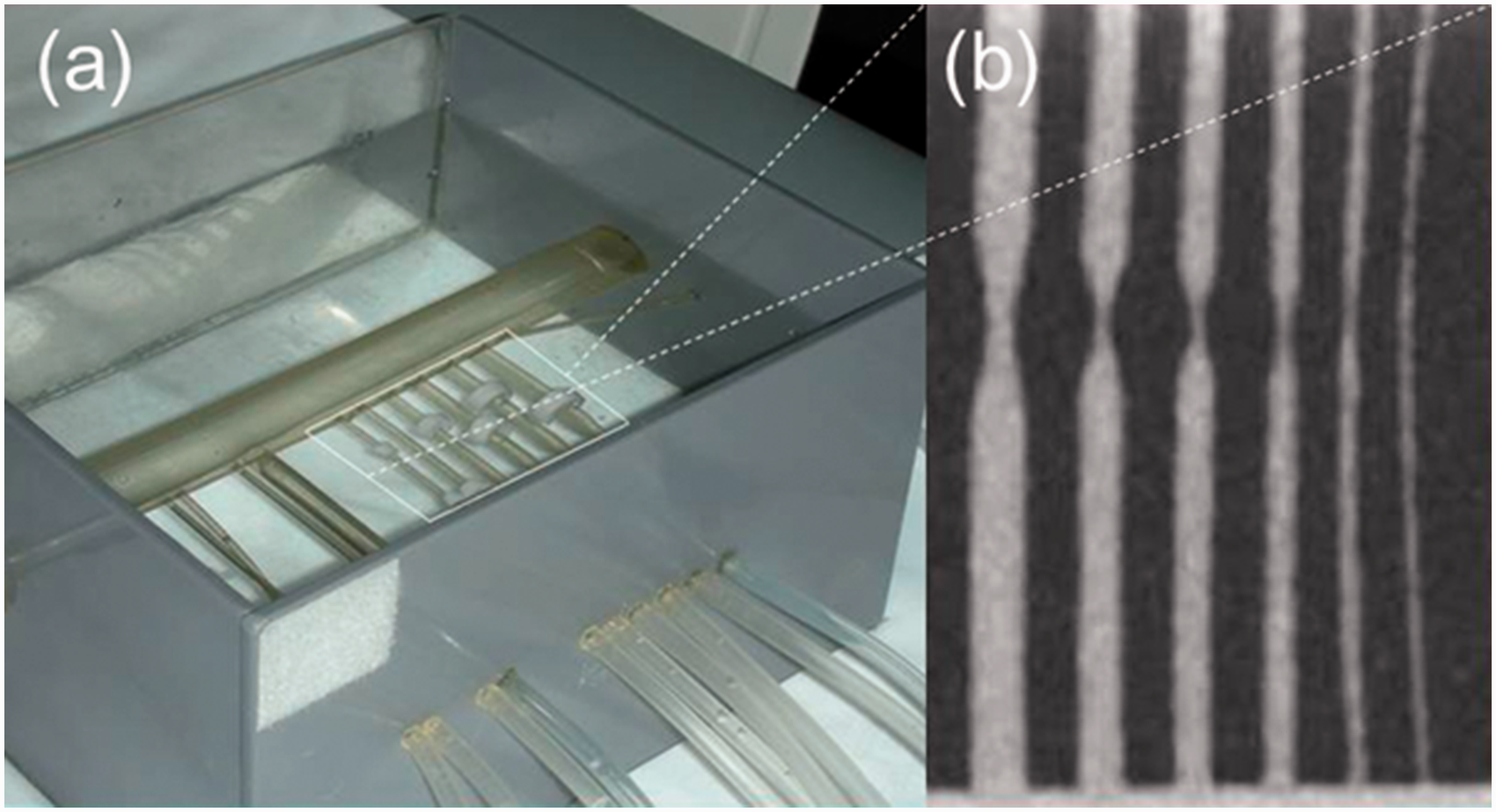

Concentration of contrast materials
Three different concentrations of contrast material (62, 111, and 170 mg iodine/mL) were made using contrast media (iopromide, Ultravist 370; Bayer Schering, Berlin, Germany) and normal saline. CT scans were performed to assess the attenuation of the contrast materials using 100 kVp and 192 mA. DECT scans were performed three times for the phantom vessels filled with the three different contrast materials by rotation. Finally, 108 vessel segments were included in this study.
DECT scans and post-processing for virtual calcified plaque subtraction
All CT scans were performed using a first-generation dual source CT, SOMATOM Definition Dual Source CT system (Siemens, Forchheim, Germany). The DECT datasets were acquired with one tube using 80 kV and the other tube using 140 kV. The tube parameter of the first tube was 425 mAs, while the second tube was operated at 100 mAs. The other parameters were the same for both tubes: collimation = 0.6, pitch = 0.7, rotation time = 1.0 s with reconstruction kernel of D30f, and field of view (FOV) = 25 × 25 cm. Merged DECT images were reconstructed with 1.5-mm thickness at 0.75-mm increments. Virtual calcified plaque subtraction CT images were generated using the “body bone removal” post-processing algorithm of the DECT application on a dedicated workstation (Leonardo, Siemens). Resultant images were transferred to a dedicated workstation (AquariusNET, version 1.8.0.3; TeraRecon, San Mateo, CA, USA) for the automatic measurement of phantom vessel lumen area.
Lumen area measurement
The lumen area (expressed as A0) of vessel segments, where each calcified plaque was subtracted and was automatically measured using a dedicated workstation. The minimum value of lumen area among the automatically measured values for each vessel segments was recorded, because the minimum lumen area represented stenosis degree of the vessel segment in CTA. Reference lumen area of vessel phantom (expressed as A1) was defined as the known value of each phantom vessel (25.5, 18.9, 12.0, 7.1, 2.8, and 1.3 mm2).
Evaluation of accuracy and effect of variables
To assess the accuracy of virtual calcified plaque subtraction images for vessel lumen area, discrepancies between the reference value of lumen area and measured lumen area (expressed as AD) were calculated. Lumen area underestimation percentage on virtual calcified plaque subtraction images (expressed as AU) were also calculated to avoid the effect of vessel diameter for measurement accuracy. AU was divided into four categories: <25%, 25–49%, 50–74%, and 75–100%. The effects of contrast material concentration, density and thickness of calcified plaque, and vessel diameter for lumen area underestimation were evaluated. Subgroup analysis was done by multiple comparisons to show the effect of variables to lumen area discrepancy or lumen area underestimation.
Statistical analysis
All data were expressed as the mean ± standard deviation (SD) unless otherwise stated. We used one-sample t tests to evaluate lumen area discrepancy. Because lumen area underestimation exhibited high skewness, normal distribution was approximated by logarithmic transformation. The Kolomogorov–Smirnov test was used to test whether Log (ln) transformation of lumen area underestimation (ln_AU) showed normal distribution. Univariate general linear model (GLM) analysis was performed to reveal the effect of contrast material concentration, calcified plaque density, calcified plaque thickness, and vessel diameter for ln_AU. Bonferroni adjusted P values were used for multiple comparisons. A P value of <0.05 was considered statistically significant. Statistical analysis was performed with commercially available statistical software, SPSS version 20.0 (SPSS, Inc., Chicago, IL, USA).
Results
Accuracy of calcified plaque subtraction
Of the 108 phantom vessel segments, 67 demonstrated measurable opacity in the lumen from calcified plaque subtraction CT images (Fig. 3). No measurable lumen was found in vessel segments of 1.9 mm and 1.3 mm. Measured lumen area was significantly smaller than reference lumen area (P < 0.001). Overall AD and AU was 6.1 ± 4.8 mm2 (range = 1.3–25.0 mm2) and 69.8 ± 29.4% (range = 18.5–100.0%), respectively. Table 1 shows lumen area measured on virtual calcified plaque subtraction images in each vessel diameter group, AD, and AU. AU of <25% was found in 12.5% (n = 9), 25–49% in 41.7% (n = 30), 50–74% in 22.2% (n = 16), and 75–100% in 23.6% (n = 17) of samples.
Maximum intensity projection (MIP) images of automatic calcified plaque subtraction DECT for vessel phantom. (a) Pre-subtraction (left) and calcified plaque subtraction (right) MIP images of vessel phantom filled with normal saline showed no luminal enhancement of vessels. For the vessels of 1.9 mm and 1.3 mm in lumen diameter, two calcified plaques (arrows) were added to replace two transformed plaques (arrowheads). Pre-subtraction (left) and calcified plaque subtraction (right) MIP images of vessel phantom filled with contrast material of (b) 62 mg iodine/mL, (c) 111 mg iodine/mL, and (d) 170 mg iodine/mL demonstrate variable vessel luminal enhancement. Measured lumen area in calcified plaque subtraction images of DECT, lumen area discrepancy, and lumen area underestimation. Data are presented as the mean ± standard deviation. Lumen area discrepancy = measured lumen area (A1) – reference value (A0). Lumen area underestimation = {(A1–A0)/A1} × 100.

Effect of variables for lumen area measurement
General linear model analysis showing the effect of contrast material concentration, calcified plaque density, calcified plaque thickness, and phantom vessel diameter for the lumen area underestimation in automatic calcified plaque subtraction images on DECT.

F value is the ratio of the model mean square to the error mean square.
Log transformation of lumen area underestimation was used for general linear model analysis.
df, degree of freedom.

Box plots showing distribution of log-transformed lumen area underestimation (ln_AU) in (a) contrast material concentration, (b) calcium plaque density, (c) calcium plaque thickness, and (d) vessel lumen diameter groups. Each P value represents to the result of post-host multiple comparison tests of general linear model analysis.
Discussion
The main findings of this study were that: (i) there was a substantial underestimation of lumen area on the calcified plaque subtraction DECT images; (ii) lumen area underestimation was lower in larger diameter lumen vessels; and (iii) lumen area underestimation was higher in lower concentrations of the contrast material. It has been reported that the accuracy of plaque subtraction in lower extremity DECT angiography was higher in larger vessels (>5 mm) such as pelvic and thigh vasculature (11,14,15); whereas the performance of this technique was inferior in smaller crural arteries in the calf (15–17). The inferior performance in smaller arteries corresponds to our result showing that lumen area underestimation was higher in smaller diameter of vessels. Regarding normal diameter of popliteal artery (9 ± 2 mm) or crural arteries (2–5 mm) (18,19), phantom vessels observed here might correspond to the size of crural arteries. Small phantom vessels limited accurate subtraction of calcified plaque in DECT images in this study. Our findings agree with a previous study showing that differentiation of calcified plaque from iodine on DECT was partially restricted by spatial resolution owing to the small size of phantom vessel (20).
Over-removal of calcified plaque resulting from apparent luminal narrowing was reported in a previous clinical study performing lower extremity CTA with DECT-based plaque removal tool (16). In that study, residual opacified lumen from calcified plaque subtraction images was better visualized in 43% of cases, but worse in 12% of cases. Another study demonstrated that a lower-extremity DECT angiographic dataset in cadaveric specimen with below-knee calcified plaques demonstrated inappropriate calcified plaque suppression in the small vessels (21). Similarly, our results showed that over-removal of calcified plaque made no residual luminal opacification on very small vessels of 1.9 mm and 1.3 mm in lumen diameter.
Although DECT has been known to enhance accuracy of calcified plaque quantification by reducing effects of tissue blooming and beam hardening beyond traditional single-energy MDCT (22), the artifacts in calcified plaque subtraction images still prevent exact differentiation between iodine contrast material and calcified plaque in small vessels (23). Specifically, calcified plaque subtraction in DECT images cannot effectively differentiate calcium from the iodine at the area of blooming artifacts (24). Thus, calcified plaque subtraction is more effective at higher contrast material concentrations or larger diameter of lumen of vessels, which compensates for blooming artefacts of calcified plaque for the vessel lumen.
This study revealed that lumen area measurement on calcified plaque subtraction DECT images was more accurate with higher concentrations of contrast material, which is in agreement with results from previous studies (21,25). Those studies showed that calcified plaque suppression in DECT was more accurate with higher concentrations of iodine within the vessels.
Calcified plaque density had a significant effect on lumen area measurement in DECT angiography in this study. Higher calcified plaque density resulted in increased lumen area underestimation. This was not in agreement with results from a previous experimental study where higher calcified plaque density ensured more accurate differentiation from the iodine in the vessel lumen (21). It is likely that the previous study did not consider interaction between iodine and calcium along the boundary of the two materials.
This study was the first phantom experiment showing the feasibility of calcified plaque subtraction of DECT using artificial calcified plaque for small sized vessels. The main strengths of this study include the control of variables that affected measurement accuracy such as iodine contrast material concentration, lumen diameter, calcified plaque density or thickness, and comparison to exact reference lumen area. Thus, the accuracy of the measurement and effect of variables, which is difficult to demonstrate in clinical studies, having various density or size of calcified plaque, were precisely evaluated in this study.
Virtual calcified plaque or bone subtraction in lower extremity DECT angiography has substantial advantages over conventional CTA, namely, straightforward interpretation and reduced need for further post-processing (15). In addition, this technique can effectively help to cope with the data load of CTA exams (16). With recent technical improvements in DE coronary CTA (26), subtraction of calcified plaque would be feasible even in the coronary arteries.
There were several limitations to our study. First, the experimental setup simulating lower extremity represented an idealized anatomic environment. The effect of another extremity in a real CT axial scan was not considered in this study. Second, artificial calcified plaques showed slightly different shapes and dimensions among each other. The effect of plaque shape for the over-removal of calcified plaque in virtual calcified plaque subtraction DECT images was not evaluated. Third, DECT scans were performed using a first-generation dual source CT scanner. Further study is necessary to assess the feasibility of calcified plaque subtraction images using recent DECT scanner and advanced technique such as iterative reconstruction or mono-energetic images.
In conclusion, calcified plaque subtraction in DECT makes substantial underestimation for the vessel lumen area measurement. Higher vascular enhancement in larger vessels ensures more accurate subtraction of calcified plaque. Cautious interpretation of virtual calcified plaque subtraction images in DECT are needed to avoid false diagnosis for vascular stenosis.
Footnotes
Declaration of conflicting interests
The author(s) declared no potential conflicts of interest with respect to the research, authorship, and/or publication of this article.
Funding
The author(s) disclosed receipt of the following financial support for the research, authorship, and/or publication of this article: This research was supported by a grant of the Korea Health Technology R&D Project through the Korea Health Industry Development Institute (KHIDI), funded by the Ministry of Health & Welfare, Republic of Korea (grant no. HI15C1532).