
Abstract
Background
Instrumented wheelchair wheels can be used to study the kinematics and kinetics of manual wheelchair propulsion. The objective of this study was to evaluate the impact of instrumented wheels on the inertial and frictional parameters of a wheelchair system.
Methods
This study compared mechanical parameters of an ultralightweight rigid frame wheelchair configured with pairs of SMARTwheels and spoke pneumatic wheels and loaded with an ISO 75 kg wheelchair dummy. Rectilinear and turning inertia of the occupied wheelchair and the rotational inertia of drive wheels were measured. A coast-down test measured frictional energy loss during straight and turning trajectories.
Findings
The addition of instrumented wheels increased occupied system mass by about 6% and turning inertia by about 16%. Frictional energy loss increased by over 40% in a straight trajectory and over 30% during turning.
Interpretation
Addition of instrumented increased the inertia and frictional energy loss of the wheelchair system. These relative effects will impact the wheelchair operator and increase the instantaneous propulsion torque during wheelchair maneuvers. The impacts will be less under conditions involving little or no change in velocity. Researchers should be encouraged to report changes in mass and weight distribution induced by addition of instrumented wheelchair wheels.
Introduction
To study the biomechanics of wheelchair propulsion, researchers and clinicians have used instrumented wheels with force-sensing push-rims.1–3 These instrumented wheels show accuracy in measuring forces,4,5 and recently demonstrated reliability while documenting the minimal detectable change. 6 Due to their design and measurement requirements, instrumented wheels have a greater mass compared with regular wheelchair wheels. From a mechanical design standpoint, the addition of instrumented drive wheels will influence a wheelchair system’s inertia and frictional energy loss. Changes in these parameters can potentially impact the measurement of propulsion forces. The objective of this study was to evaluate the impact of instrumented wheels on the inertial and frictional parameters of a wheelchair system.
Methods
This study compared mechanical parameters of an ultralightweight rigid frame wheelchair (TiLite Aero Z, Pasco, Washington) configured with pairs of 24″ SMARTwheels (Out-Front, Mesa, AZ) and spoke wheels with 1-3/8″ pneumatic tires, respectively. Drive wheel axles were configured in two positions to alter weight distribution. The positions differed by 3 cm and were positioned 4.5 and 6.5 cm forward of backrest canes. The wheelchair was loaded with an ISO 7176-11 75 kg dummy during testing (Figure 1).
7
TiLite wheelchair loaded with ISO dummy on iMachine.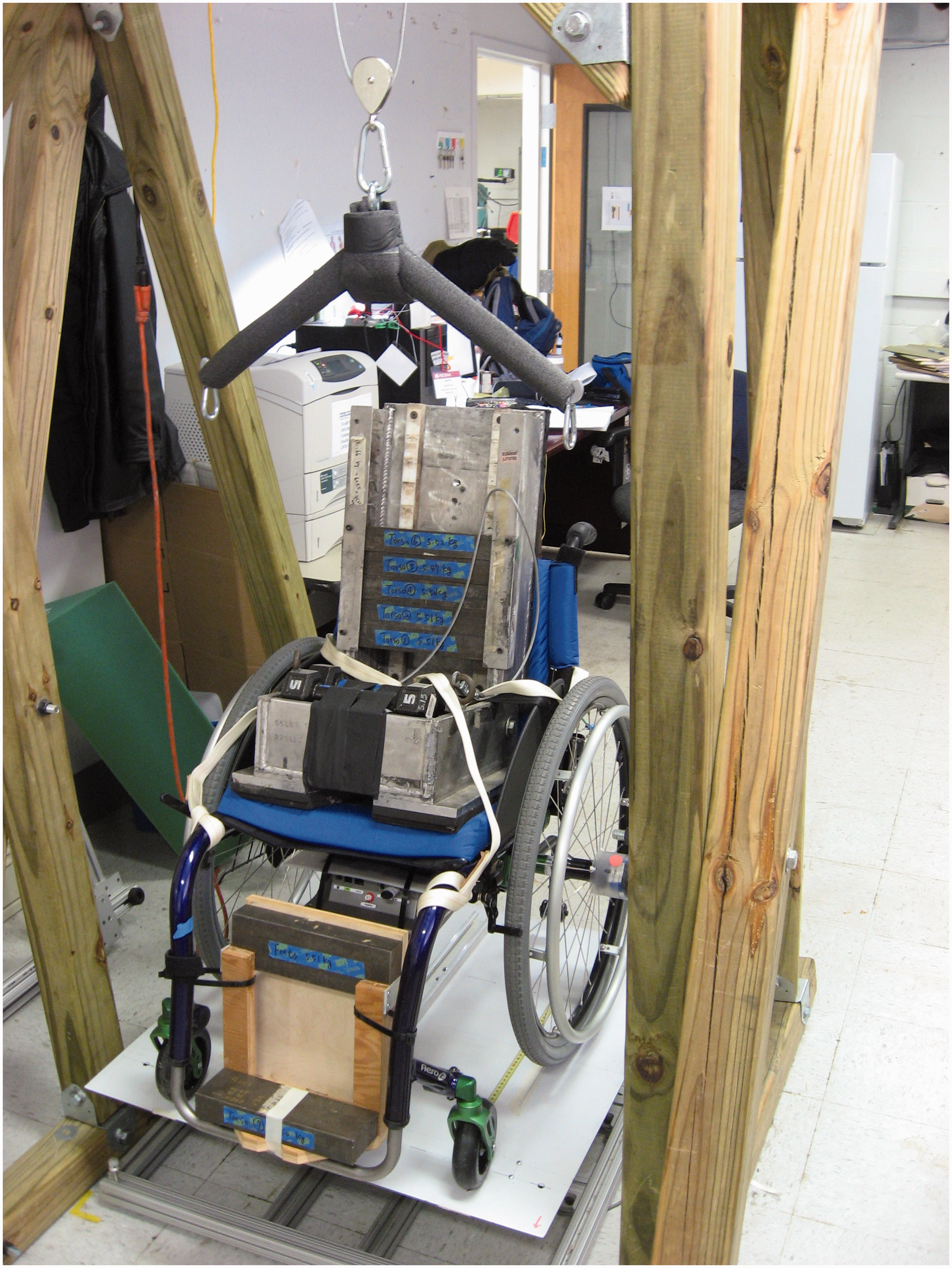
Other than the different drive wheels, no differences existed between the spoke and SMARTwheel configurations. Inertial parameters of the loaded wheelchair system, including mass, weight distribution, and yaw (or turning) inertia, were measured using the iMachine, 8 a device designed for this purpose. The iMachine is a damped, rotational platform that, when given an initial displacement, will oscillate about its yaw axis with the behavior of a damped simple harmonic system (Figure 1). Measurement of the loaded system’s natural frequency is then used to determine the yaw moment of inertia.The rotational inertia of the instrumented and spoke wheels were measured using a trifilar pendulum. 9 A coast-down protocol was deployed to measure frictional energy loss during straight trajectories and fixed-wheel turns. 10 This technique involved manually pushing the occupied wheelchair to a targeted speed and releasing it. Direct measurement of wheel velocities were used to calculate decelerations of the wheelchair’s center of mass using the average of three trials. Additional calculations were performed to estimate force and torque energy loss using free-body diagrams of the respective maneuvers based upon rolling resistance and resistive torque scrub.10,11 Measurements for left and right turns were averaged to provide a single value.
Results
Inertial parameters of SMARTwheel and spoke wheel.

Inertial Parameters of occupied wheelchair.

Resistive energy loss of occupied wheelchair.

Discussion
This analysis was undertaken to fully report the inertias of an instrumented wheel and to measure the frictional energy loss during straight and turning trajectories. To maneuver a manual wheelchair, users apply torque to the push-rims to overcome the inertial and frictional resistances of the wheelchair in order to impart changes in velocity (speed and/or direction).
From a mechanical perspective, an increase in rectilinear inertia (system mass) will have the greatest impact during changes in velocity because it is the dominant system inertia. 12 The SMARTwheels added about 6% to the system’s rectilinear (mass) inertia when occupied by a 75 kg dummy, but their addition resulted in much greater increases in rotational and yaw inertias and frictional energy losses. The addition of SMARTwheels increased yaw inertia by over 16%, which will increase the effort required while turning. Increased effort will be greater when accelerating or turning the chair rapidly rather than slowly. 13 Frictional energy loss was increased by 30–70% as manifested by rolling resistance and tire scrub. The greater energy loss is consistent with the additional mass of instrumented wheels and by their effect on weight distribution in addition to potential differences due to tire type and bearing friction compared with the wheelchair configured with spoke pneumatic wheels.
Frictional energy loss is ever-present, thus has an impact whenever tires are rolling or scrubbing on a surface. Increased energy loss will influence the wheelchair system in at least two manners. Firstly, the cyclic nature of propulsion involves a sequence of applying torque to the push-rims followed by a period of free-wheeling during which the wheelchair slows down. 12 An increase in resistive energy loss will induce greater deceleration during free-wheeling, which requires the user to impart more torque to accelerate the system in order to maintain a steady speed. This additional torque is due to both the need to overcome the greater reduction in speed and to overcome the additional inertias of the SMARTwheel-equipped wheelchair. Secondly, the increased energy loss must be overcome during each propulsion stroke. For example, propelling straight using a SMARTwheel-equipped chair requires the user to overcome resistive forces of 3–4 N depending on the axle position.
The heightened inertia and friction will result in instrumented wheels reporting forces and torques that are greater than those needed to propel a wheelchair without instrumented wheels. The overall effect on the operator will depend on the length and complexity of the maneuver, with the over-reporting of kinetic measurements being greatest during maneuvers with significant changes in velocity. For instance, initiating movement from a zero velocity state will be greatly impacted by the increased inertia, and the greater friction will add to the propulsion work. Similarly, maneuvers with tight turns or those that change grades (i.e. ramps) will also be impacted. Rapid and tight turns are impacted by system yaw inertia, drive wheel scrub and rolling resistance—all of which are increased when using instrumented wheels. Changes in grade require the user to impart potential energy in the system as well as overcoming greater friction; both factors will require greater work by the occupant. Conversely, instrumented wheels will have less impact on propulsion torque during straight steady-state velocities, during which the changes in velocity between propulsion strokes are minimized. The least impact, although still significant, will be realized during steady-state propulsion on a treadmill or dynamometer because the system is solely overcoming frictional resistance so the increased inertial parameters are not as influential.
The inertial and frictional impacts of instrumented wheels reported in this technical note are reflective of the wheelchair, dummy and maneuvers that were assessed. Changes in wheelchair or occupant mass, tire type, and rolling surfaces will alter the inertial and frictional parameters of the occupied wheelchair system. The selection of the wheelchair was based upon the prevalence of research using ultralightweight wheelchairs, and spoke pneumatic wheels were used as comparison because it represents the standard option when ordering these wheelchairs. Use of other components and situations may alter the relative differences between instrumented and non-instrumented wheels.
Conclusions
Instrumented wheels can be a useful measurement tool to evaluate propulsion kinematics and kinetics. However, kinetic variables are influenced by the wheelchair’s inertia and frictional parameters, both of which are increased with the addition of instrumented wheels. Moreover, these impacts differed across axle positions and cannot be considered linear. As a result, the addition of instrumented wheels may confound the comparison of propulsion effort across different wheelchairs or different configurations. Therefore, assigning causation of differences in propulsion kinetics to changes in configuration may not be possible due to these effects. Because of the importance of documenting wheelchair parameters used during testing and evaluation, researchers should be encouraged to report changes in mass and weight distribution induced by addition of instrumented wheelchair wheels. This will empower the reader with knowledge about the changes to the mechanical system being measured.
Footnotes
Acknowledgements
The authors thank Kessler Institute for Rehabilitation for loaning the instrumented wheels. This work was completed as part of the Mobility RERC, which is funded by the National Institute on Disability, Independent Living and Rehabilitation Research of the US Department of Health and Human Services under grant number 90RE5000-01-00. The opinions contained in this paper are those of the grantee and do not necessarily reflect those of the US Department of Health and Human Services.
Declaration of conflicting interests
The author(s) declared no potential conflicts of interest with respect to the research, authorship, and/or publication of this article.
Funding
The author(s) disclosed receipt of the following financial support for the research, authorship, and/or publication of this article: This work was completed as part of the Mobility RERC, which is funded by the National Institute on Disability, Independent Living and Rehabilitation Research of the US Department of Health and Human Services under grant number 90RE5000-01-00. The opinions contained in this paper are those of the grantee 4 Journal of Rehabilitation and Assistive Technologies Engineering 0(0) and do not necessarily reflect those of the US Department of Health and Human Services.