
Abstract
Objective
Initial stages of cartilage matrix calcification depend on the activity of matrix vesicles. The purpose of the study was to describe how calcified matrix vesicles join into larger structures, to present their up-to-date undescribed 3-dimensional image, and to observe how calcified matrix relates to chondrocyte lacunae.
Design
Calcified cartilage was obtained from the zone of provisional calcification of calf costochondral junctions, then enzymatically isolated and studied by microtomography, scanning electron microscopy, atomic force microscopy and X-ray diffraction, and Fourier transform infrared spectroscopy.
Results
Hyaluronidase digestion released packets of granules surrounded by the cartilage matrix. Further digestion, with collagenase and trypsin, removed matrix and exposed granules with dimensions within 50 to 150 nm range, which we consider as equivalent of calcified matrix vesicles. Granules joined into larger groups with dimensions of 0.5 to 2 μm, which we call globular units. Certain matrix vesicles appeared well connected but contained globular units that had spaces filled with electron lucent material, presumably matrix or chondrocyte remnants. Globular units were organized into massive structures taking the shape of oval plates. Comparison of these plates with lacunae containing isogenous groups of chondrocytes from proliferative zone of costochondral junction suggests that the cells from a single lacuna were responsible for the formation of one plate. The plates were connected with each other and extended over provisional calcification zone.
Conclusions
The outcome showed how particular calcified matrix vesicles associate into globular units, which organize into massive structures assuming the shape of oval plates and eventually cover large areas of cartilage matrix.
Introduction
Epiphyseal cartilage growth plate serves as the structural template for bone formation and growth. It is divided into a reserve, proliferative, and hypertrophic zone. Chondrocytes in the proliferative and hypertrophic zones are arranged in rows parallel to the long axis of the cartilage and separated by longitudinal septa. The calcifying area of the growth plate is surrounded by bone mantel (bone collar), which arises by intramembranous ossification and protects the growth plate against mechanical damage.1-3 Calcification of the cartilage matrix begins half-way into the middle of the zone of hypertrophic cells with the appearance of separate calcium deposits in or near calcifying globules of cellular origin, subsequently named matrix vesicles.4-7 Matrix vesicles contain enzymes that promote calcification.8-10 Calcium deposits accumulate within longitudinal septa and eventually fuse to large calcified areas in the bottom portion of the hypertrophic zone, a region frequently called the zone of provisional calcification. Then, in the bone metaphysis, calcium deposits serve as the substrate for early bone deposition.1-3 In earlier works, calcium deposits associated with matrix vesicles were described as hydroxyapatite (HAp) crystals, eventually forming plate-like structures. 2 Further studies demonstrated, however, that the calcium deposits represented poorly crystalline, carbonated apatite. 11 Transmission electron microscope observations indicated that the calcified matrix vesicles formed aggregates of electron dense structures, often called calcification nodules. 12 Calcium deposits observed by scanning electron microscopy (SEM) in cartilage from the rat rib costochondral growth plate (corresponding to epiphyseal plate of long bones) appeared, as structures with dimensions in the range of 0.4 to 1.5 µm, which we named globular units. In some areas, they fused with each other, but usually were separated from the neighbours by a slit measuring about 0.15 µm. 13 Thus, globular units seemed to be 3-dimensional structures representing an advanced stage of calcified matrix vesicle organization. Structures similar to globular units, named calcospherites, were previously described by Lester and Ash 14 in rat mandibular condyle.
Calcified deposits were, as far as we could establish, never isolated as the whole structure and studied by SEM and micro-computed tomography (µCT). Such visualization could show how particular calcified matrix vesicles associate into globular units and subsequently cover large areas of cartilage matrix in the zone of provisional calcification. Thus, in this work calcium deposits from costochondral junctions of calf cartilage were enzymatically isolated and observed by SEM, atomic force microscopy, and focused ion beam technology to observe calcified matrix vesicles’ aggregation into larger structures. The relationship between calcified matrix vesicle aggregates and cartilage matrix was also observed. Moreover, calcium deposits were analyzed by X-ray diffraction and Fourier transform infrared (FTIR) spectroscopy. Finally, calcium deposits were decalcified for histological observations on their organic components.
Materials and Methods
Calcified Cartilage Preparation
Rib cages from calves ranging in age from 4 to 20 weeks were purchased at the local butchery. Cartilage was dissected and secured for further processing within 24 hours after the death of the animal. The costochondral junction (an equivalent of the cartilage growth plate of long bones) was cleared from the adhering tissues and hand broken at the level of metaphysis—the provisional zone of calcification. The whole calcified cartilage layer of the rib was either cut off and fixed in 70% ethanol or calcified cartilage was scraped from the exposed surface with a knife, collected in a dry dish, frozen at −80°C, lyophilized, and pulverized in liquid nitrogen. On average, 400 mg of dried cartilage powder was obtained from one animal.
Hyaluronidase Digestion
A calcified cartilage layer cut off from the whole rib preserved in ethanol and a 400 mg pellet of pulverized cartilage were digested in 10 mL of 0.1% hyaluronidase (hyaluronidase from bovine testes, Sigma-Aldrich) dissolved in phosphate-buffered saline (PBS). 15 The progress of digestion was controlled by staining with 0.1 aqueous solution of toluidine blue (Sigma-Aldrich). Digestion lasting 4 to 5 hours was sufficient to remove all traces of stainable material.
Collagenase, DNase, Trypsin Digestion
The organic material attached to calcified cartilage after hyaluronidase digestion was removed with 0.25% collagenase and 0.05% DNase solution in PBS (Sigma-Aldrich) at 37°C for 2 hours, followed by 0.25% trypsin in 0.1 mM Tris buffer, pH 8.2 (Sigma-Aldrich) at 37°C, for 1 hour and again by 2 hour exposition to collagenase and DNase. Calcified cartilage was rinsed twice with dH2O for 15 minutes, and either left in water for µCT or spread on aluminum foil and lyophilized for SEM study. Digestion of the whole calcified cartilage layer of the rib yielded samples with dimension within micrometer to millimeter range, but they were mixed with fragments of bone collar and had to be hand-picked for further studies. Calcified cartilage fragments scrapped from the exposed rib surface were not contaminated by bone and after pulverization were considerably smaller than in the previous group. In some experiments, hyaluronidase digested material was left in a vertical position in 15-mL plastic tubes for 10 minutes to allow larger pieces of calcified cartilage to settle down and the supernatant was withdrawn leaving about 0.5 mL over the sediment. Then, the supernatant was spun down, the sediment was suspended in dH2O, and spread on the aluminum foil for SEM observations. Samples from supernatant obtained after first collagenase digestion of cartilage that were already treated with hyaluronidase were prepared in the same manner.
Micro-Computed Tomography
Samples of calcified cartilage were scanned using a microfocused X-ray tomographic system (MICRO XCT-400, Xradia, Zeiss), at 40 kV and 200 μA. For each sample, 1500 projection images were recorded with an exposure time of 10 seconds and a magnification objective of 20×. The volume 0.4 mm3 was reconstructed with the instrument software and was then exported to Avizo Fire (FEI Visualization Sciences Group) for further 3-dimensional image analysis. Voxel size was 0.5 × 0.5 × 0.5 μm.
Scanning Electron Microscopy and Focused Ion Beam Cutting
Microstructure examinations of calcified cartilage samples were done using SEM cold emission Hitachi SU-8000 operating under 5 kV and with the working distance of between 3 and 15 mm. The resolution of this microscope at 5 kV was 1.2 nm. The images were taken in secondary electron (SE) mode using upper and lower detectors. A thin Ni-Cu layer with a thickness smaller than 5 nm was deposited before SEM studies, to dissipate charging artifacts and any resultant heat buildup, and minimize beam damage. Several cross-sections images of globular units were taken using a dual beam focused ion microscope (FIB) Hitachi NB-5000. The accelerating FIB beam voltage was 40 keV and a beam current was 0.01 nA. Before cutting, each particle was deposited by ion beam with a local protective tungsten layer.
Atomic Force Microscopy (AFM)
Topography visualization of calcium deposits in calf costochondral junctions was performed using MFP 3D BIO microscope (Asylum Research/Oxford Instruments). Stable and controllable experiment conditions were ensured by closing AFM in a custom-made chamber that precludes temperature fluctuations. The microscope was operating in semi-contact mode. To register high-resolution topographical maps, a silicon AC160TS-R3 (Olympus) scanning probe was used. According to the producer, the probe is characterized with spring constant approximately 26 N/m. The radius of the tip (~9 nm) used for the imaging was estimated with calibration grating provided by the microscope’s producer. Samples were imaged over an area of 5 × 5 μm at 0.3 to 0.4 Hz. IgorPro (version 6.17), a professional, dedicated software provided by the microscope’s producer, was used for data analysis.
Fourier Transform Infrared Analysis
Calcified cartilage samples for infrared (IR) analysis were deposited on the aluminum foil. FTIR spectra were recorded on Nicolet 8700 spectrometer (Thermo Scientific) in attenuated total reflection–FTIR mode (ATR-FTIR) with diamond crystal. For each sample, 256 scans in the range of 400 to 4000 cm−1 and with resolution of 4 cm−1 were collected. For more detailed analysis, the peak resolve, preceded by the Fourier self-deconvolution (FSD), for ν4PO4 + HPO4 band was performed with the OMNIC software. The FSD procedure was done with a bandwidth of 22 cm−1 and sensitivity coefficient (enhancement) of 2. Spectral decomposition was done after linear base line subtraction and a Lorentzian shape of the bands was used.
X-Ray Diffraction
The crystalline phases of calcified cartilage samples were studied by X-ray diffractometry (XRD) using a Rigaku Miniflex II diffractometer and a Cu Kα radiation source. The diffractograms were recorded from 2θ = 3° to 55° with a step size of 0.02° and a scan time of 10 seconds per step. Peak identification for crystalline phases was achieved using the International Centre for Diffraction Data (ICDD).
Histological Staining
Fragments of the whole rib cartilage were fixed in 70% ethanol, dehydrated, embedded in paraffin, sectioned at 6 µm, and stained with hematoxylin-eosin. Fragments of the enzymatically treated calcified cartilage were rinsed in calf serum to inactivate trypsin and decalcified in 10% ethylenediaminetetraacetic acid in 4% formaldehyde to expose cartilage matrix masked by calcium deposits. After rinsing in dH2O, decalcified fragments of matrix were used for preparation of smears on Silane-Prep slides (Sigma-Aldrich). Smears were dried at 37°C and used for hematoxylin-eosin, glycosaminoglycans, and collagen type II staining. Glycosaminoglycans were stained with 1% Alcian blue 8GX (Sigma-Aldrich) solution in acetic acid, pH 2.5 for 60 minutes. Collagen type II was detected in smears and in sections of formalin-fixed and paraffin-embedded rib cartilage, used as a positive control. Mouse monoclonal anti
Results
Morphological Evaluation
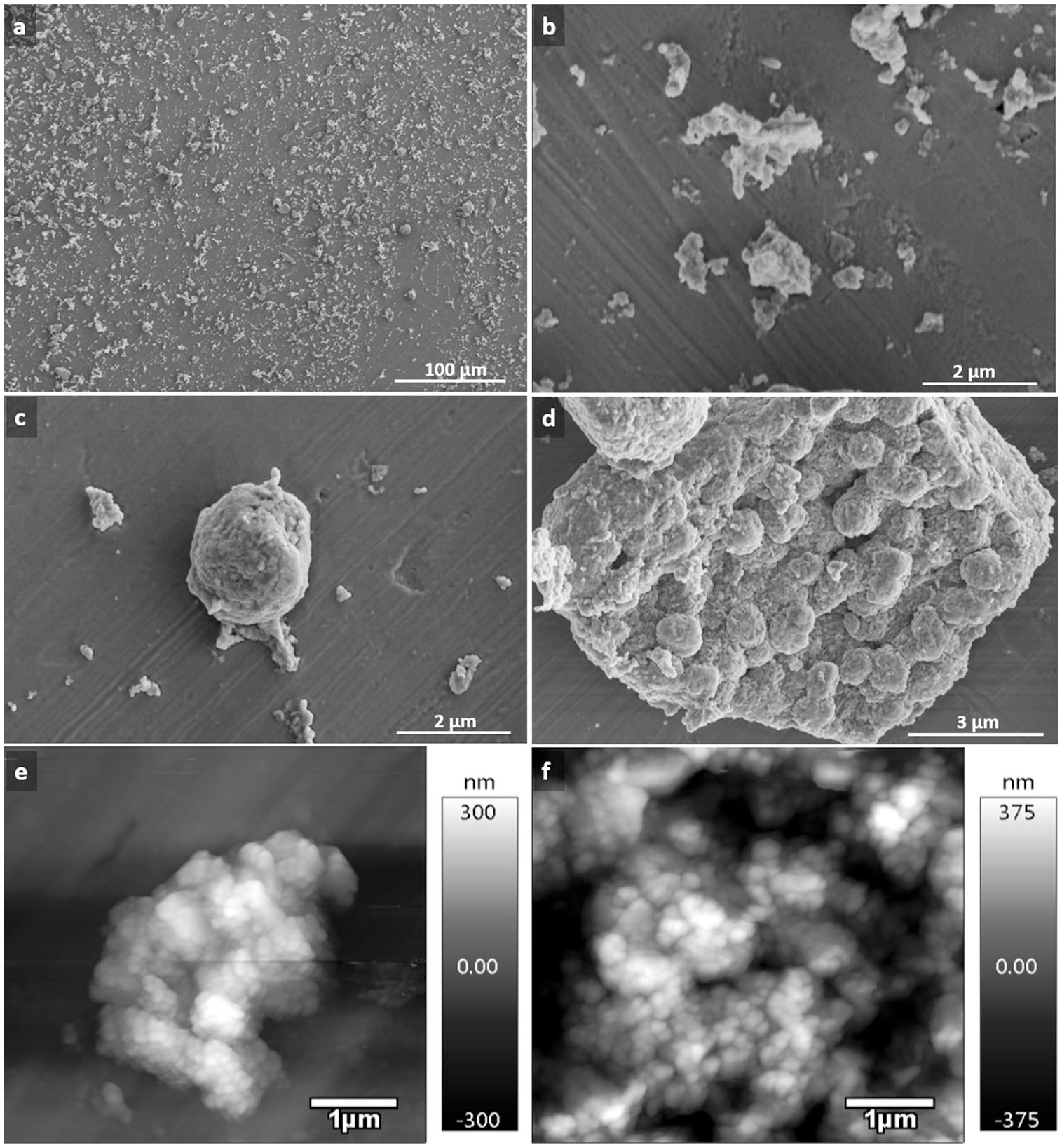
Hyaluronidase digestion released several groups of granules embedded in matrix proteins (
Scanning electron micrographs of calcium deposits released from matrix by enzymatic digestions. (
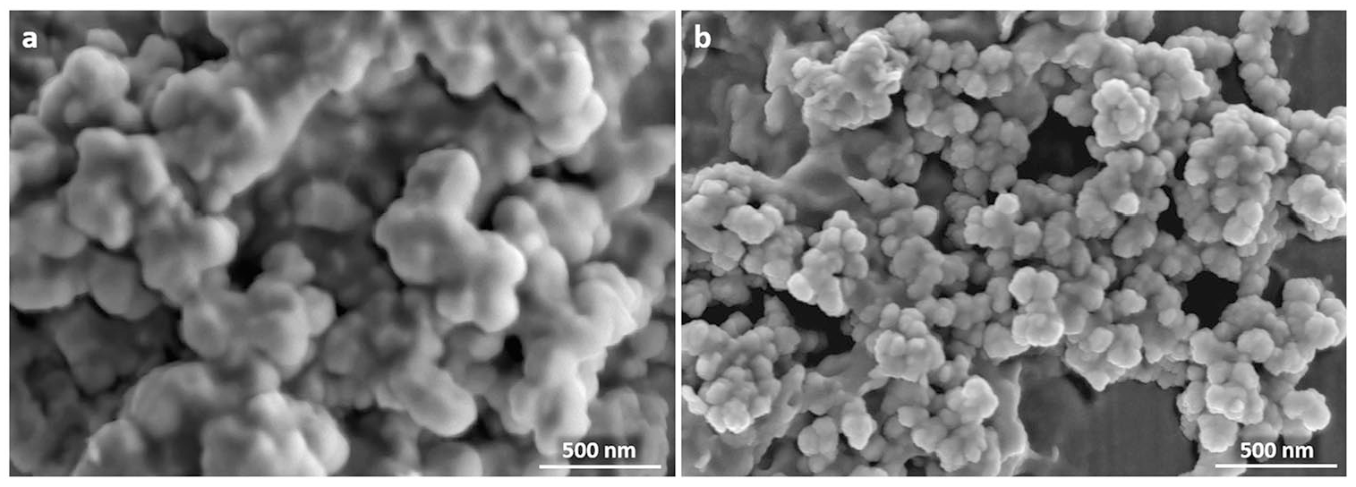
Calcium deposits released from matrix by enzymatic digestions displayed a variety of forms, from single mineralized matrix vesicles to large conglomerates, globular units (
Scanning electron micrographs showing examples of formation and arrangement of globular units: (
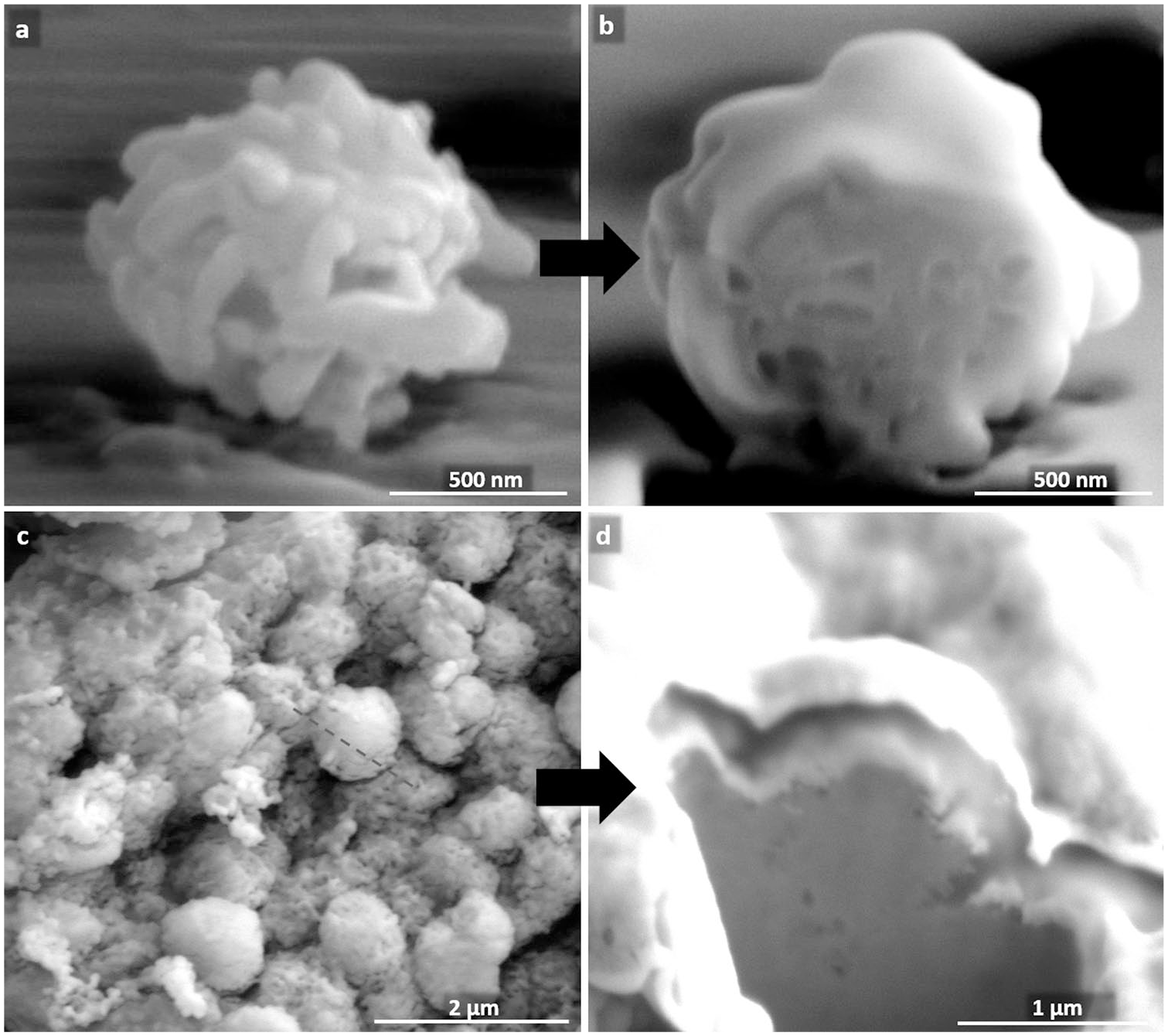
Demonstration of electron lucent spaces within globular units. (
Globular units, associated into massive agglomerates (
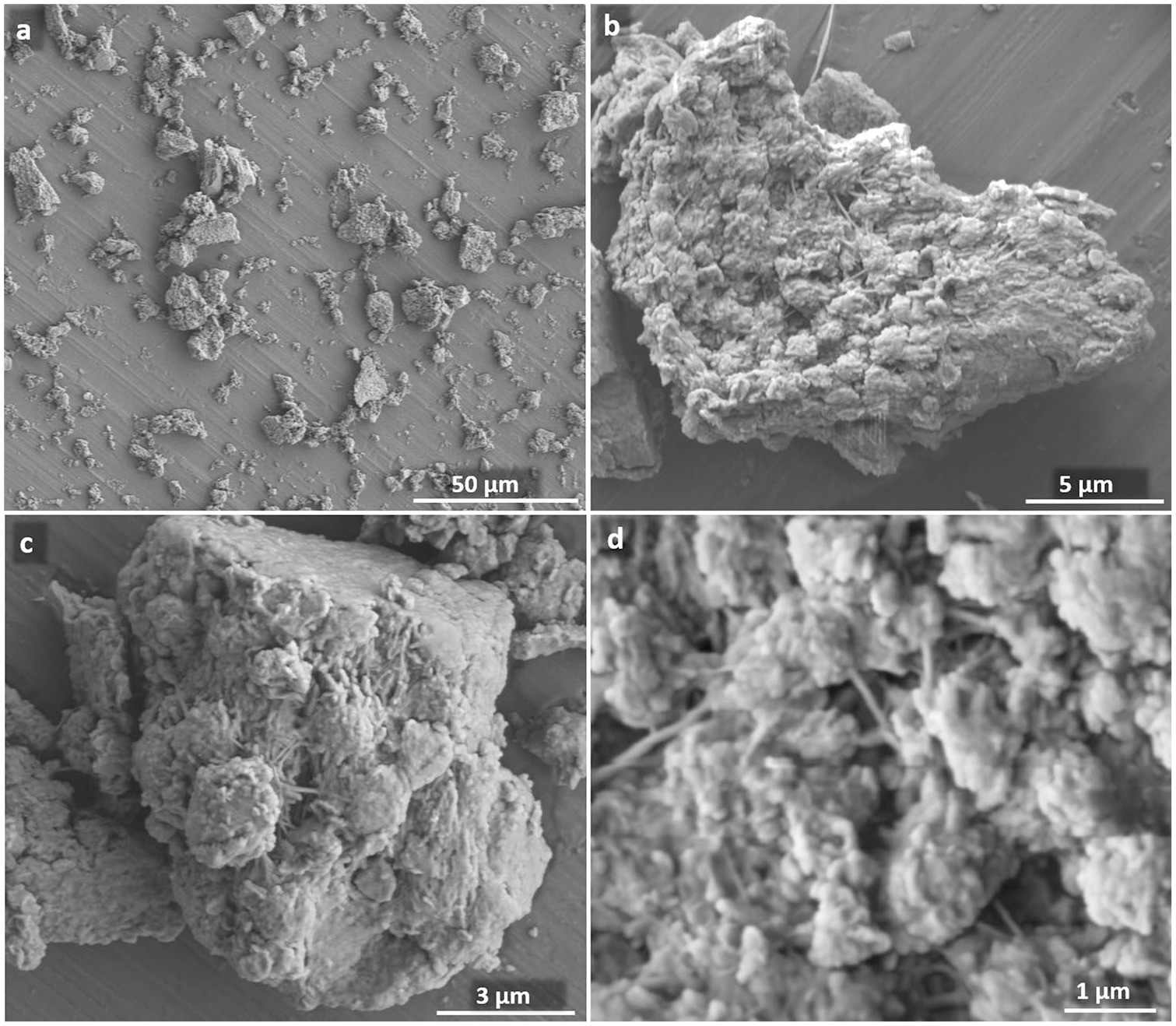
Scanning electron micrographs of architecture of clusters formed by globular units. (
Massive structures formed by globular units had an impressive appearance, but their real position was visible only in preparations made from nonpulverized cartilage. As shown in
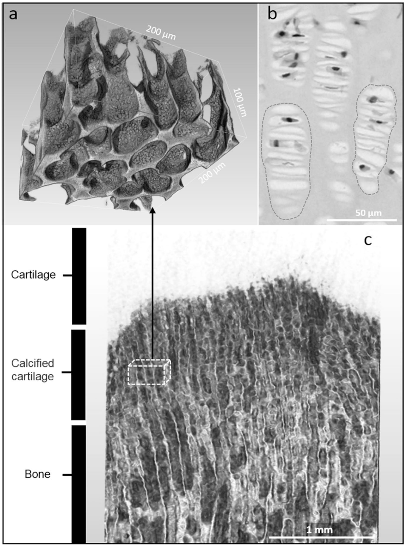
Localization of massive structures formed by globular units. (
Physicochemical Evaluation
Spectra obtained from FTIR analysis were typical for crystalline forms of calcium phosphate ceramics (
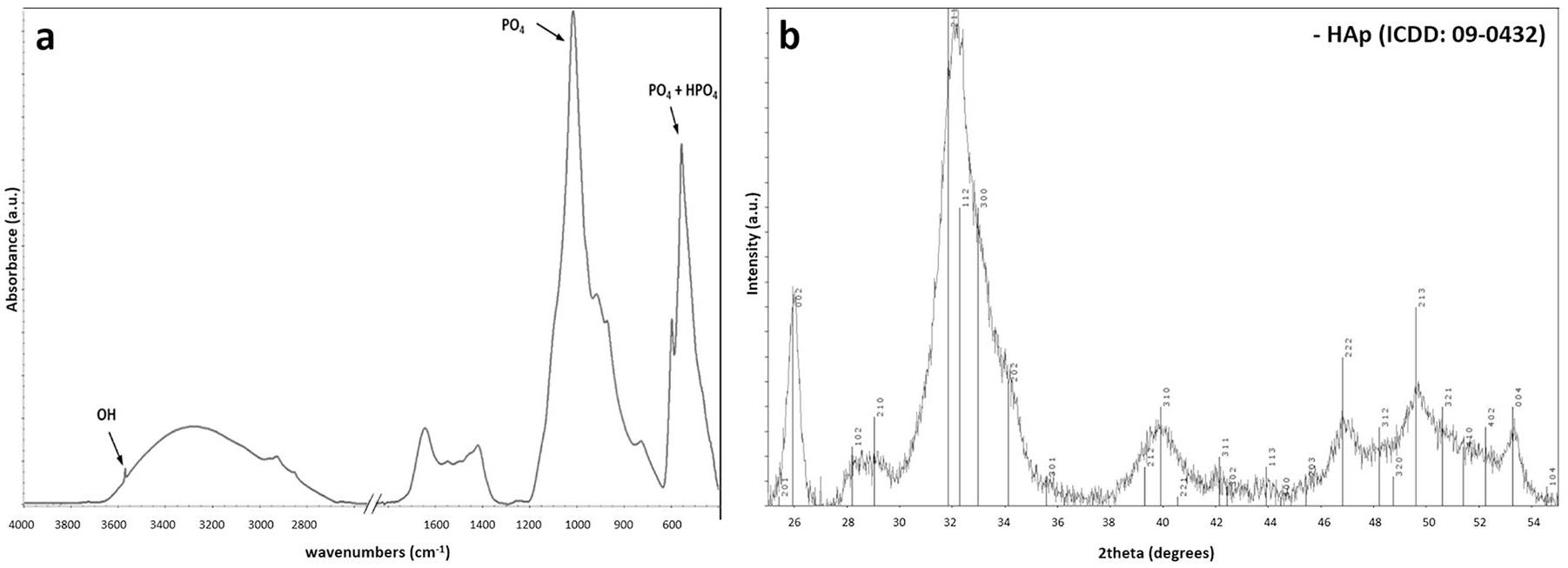
Crystal and chemical structure of calcified deposits from costochondral junction cleared of adhering organic matter by enzymatic digestion. (a) Fourier transform infrared (FTIR) spectra, with indicated characteristic bands OH, PO4, and HPO4. (b) X-ray diffractogram: broad peaks appeared only within the hydroxyapatite region.
Results of Peak Separation for ν4PO4 + HPO4 Band a .
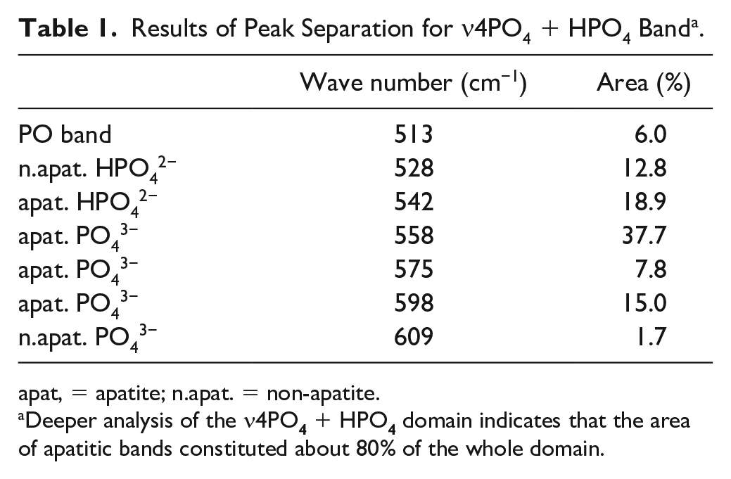
apat, = apatite; n.apat. = non-apatite.
Deeper analysis of the ν4PO
The XRD patterns obtained for calcified deposits are shown in
Histological Evaluation
Material left after decalcification of the pulverized, enzymatically purified calcium deposits was acellular and contained glycosaminoglycans and collagen type II. Clear demonstration of collagen was possible only after the removal of glycosaminoglycans by hyaluronidase (
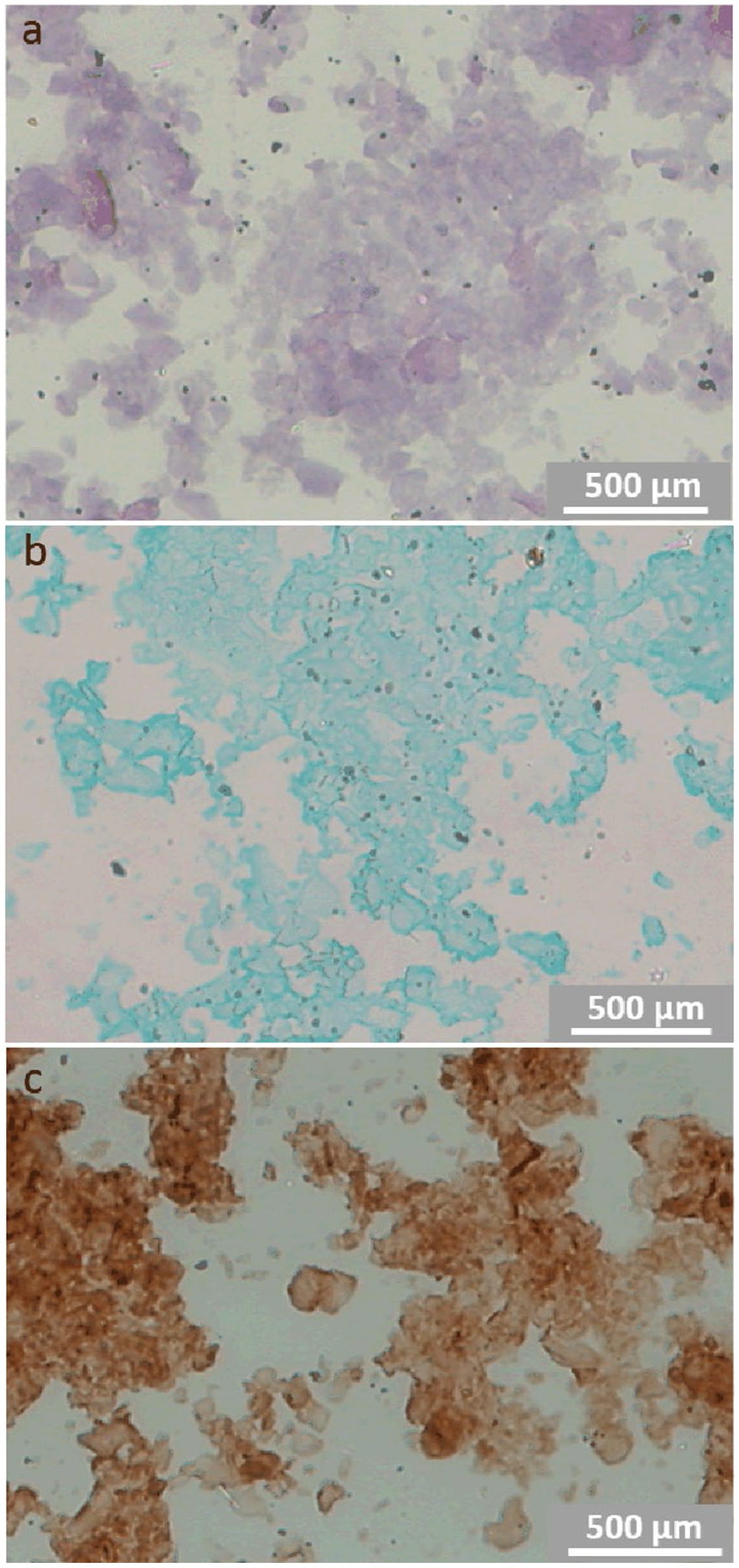
Smears of organic material left after ethylenediaminetetraacetic acid (EDTA) decalcification of calcium deposits. (
Discussion
Calcium deposits could be easily released from the adhering matrix by enzymatic treatment. This new approach enabled SEM demonstration of calcium accumulations occurring as single granules, doublets, triplets, and larger groups of granules, which eventually coalesced into globular units (
The comparison of oval plates (
Schenk et al. 22 observed that about two-thirds of the longitudinal septa in the tibial epiphyseal plate were partially or completely mineralized, while the remainder were essentially nonmineralized. Similarly, noncalcified matrix in close apposition to globular units was observed within costochondral junction of rat ribs. 13 Thus, it appears that the nonmineralized matrix remained in regions too remote from chondrocytes to deposit packets of matrix vesicles.
While in the earlier work, the character of calcium deposits in matrix vesicles was a matter of controversy,18,23 more recent studies shown that matrix vesicles isolated from chondrocyte formed hydroxyapatite-like crystals, demonstrated by XRD 20 and by FTIR with peaks at 960, 1025, 1102, 1065, and 1157 cm−1,24 reviewed in Kirsch. 25 Our material consisted of whole calcium deposits rather than isolated matrix vesicles and we observed similar patterns in FTIR and XRD spectra.
According to Kim et al., 11 apatite crystals isolated from epiphyseal plates assumed the form of wide, very thin rectangular plates gathered in small clusters. They had an average length of 103 ± 26 and average width of 68 ± 16 nm. Electron microscope observations of Bonucci and Gomez 26 indicated presence of crystals of a needle- or filament-like shape with the length of 40 to 160 nm and thickness from 2 to 5 nm. Therefore, each mature matrix vesicle contains considerable a number of crystals kept together by some components of cartilage matrix. Thus, matrix vesicles may be considered organic-inorganic hybrids, each consisting of an organic filament with attached calcium and phosphate ions.12,26 Recently, the specific role in matrix vesicles’ mineralization was ascribed to annexins, proteins present in the nucleational core of native matrix vesicles.9,25,27
The question arises how singular matrix vesicles are joined into globular units and how the latter form massive structures. All these structures resisted mechanical treatment during cartilage milling and enzymatic digestion removing the noncalcified matrix, thus connection between the particular calcified elements must be strong. Conceivably, their aggregation resulted from the activity of the tissue-nonspecific isozyme of alkaline phosphatase (TNAP). The role of this enzyme in cartilage and bone calcification is well established.9,28-30 Phosphatases catalyze the hydrolysis of phosphomonoesters with the release of inorganic phosphate. 31 In mineralizing tissues, TNAP may hydrolyze inorganic pyrophosphate or pyridoxal phosphate to generate inorganic phosphate promoting mineralization.30,32 TNAP is linked to the outside of the plasma membrane via glycosylphosphatidylinositol 32 and has the crown domain with the collagen binding loop. 33 Thus, TNAP still bound to cell membrane of chondrocytes or released from the membrane and attached to collagen could provide phosphate groups needed to bridge the particular matrix vesicles into globular units and larger structures present in the zone of provisional calcification. We have not been able to detect TNAP by histochemical staining, but, as quoted above, its activity in mineralizing tissues is well established and, in our material, could be lost or inactivated during preparatory procedures.
Suspension bridges, shown in
To summarize, while the beginning of cartilage calcification due to the activity of matrix vesicles is well documented, the further steps leading to the formation of massive plate-like structures in the zone of provisional calcification is less known. Enzymatic digestion of calcified cartilage may begin to help to clarify the unknowns. This method releases single calcified granules, allows the observation of their associations into larger structures, and may form the basis for studies on the molecular mechanism responsible for their formation.
Footnotes
Authors’ Note
The work reported was done in the Department of Histology and Embryology, Medical University of Warsaw and Faculty of Materials Science and Engineering, Warsaw University of Technology.
Acknowledgments and Funding
We are grateful to Ian Thomas Behnke Byrnes for his comments on the manuscript. The author(s) disclosed receipt of the following financial support for the research, authorship, and/or publication of this article: This research was supported by the National Science Centre (2016/21/B/NZ1/00289) and the National Centre for Research and Development (STRATEGMED3/306888/NCBR/2017).
Declaration of Conflicting Interests
The author(s) declared no potential conflicts of interest with respect to the research, authorship, and/or publication of this article.
Ethical Approval
Not applicable.
Animal Welfare
Not applicable.