
Abstract
The synthesis of CdS nanoparticles was developed based on the unconventional design of bioelectrochemical system (BES) inoculated with Shewanella sp. HN-41. The BES configuration included two bottle chambers separated by silicon membrane but directly connected by a graphite electrode perforating through silicon membrane, namely, non-external circuit bioelectrochemical system (nec_BES). Shewanella sp. HN-41 in the anode of nec_BES consumed lactate and transferred electrons to the graphite electrode end in the anode and, in its turn, the graphite electrode end in the cathode reduced directly thiosulfate to sulphide, forming CdS nanoparticles after 21 days. CdS nanoparticles with the average size of approximately 17 nm were synthesized in the cathode solution. The hollow, spherical, and void structure of particles was observed by transmission electron microscopy (TEM) and scanning electron microscopy (SEM) images. The energy dispersive X-ray spectroscopy (EDS) study confirmed the nanoparticles contained Cd and S elements, and X-ray diffraction (XRD) data showed a strong crystalline phase and mixed crystallites of CdS nanoparticles. The UV-Vis absorption spectra of CdS nanoparticles revealed the blue shift in excitonic transition with respect to CdS bulk material, suggesting its potential application in optical studies. The bioelectrochemical system can be applied for the removal and preparation of other sulphide heavy metals.
Introduction
In the last few years, cadmium sulphide nanoparticles (CdS-NPs) attracted lots of attention from researchers because of their extraordinary properties. A direct band gap of 2.48 eV at room temperature makes CdS an extraordinary II–VI semiconductor. 1 Owing to their optical, thermal, and electrical properties, nanometer-sized CdS materials had many outstanding applications in the different fields such as solar cells,2,3 photo-detectors (photo-sensors),4–6 optoelectronic devices,7,8 nonlinear optical materials, various luminescence devices, photochemical catalysis, and detectors for laser and infrared, metallic, delivery.9,10 Besides, the luminescent effect of CdS nanoparticles was found for their application as fluorescence probes in the quantitative analysis of nucleic acids. 11 Furthermore, CdS-NPs were applied in different electrochemical sensing systems such as glucose biosensor 12 and organophosphate biosensor. 13 For further applications, many routes for CdS-NP synthesis have been reported such as thermal evaporation, 14 chemical vapor deposition, 15 solvo-thermal synthesis, 16 and hydrothermal process, 17 but most of these routes are toxic, energy-consumed, or difficult to handle.
Recently, the bioelectrochemical systems have been viewed as a potential bioelectrochemical means of using organic chemical energy in the application of environmental sciences for both organic wastewater and metals removal or synthesis.18–20 Conventionally, BESs were designed with two chambers, anode and cathode separated by proton exchange membrane (PEM); and the two chambers were connected together by an external circuit. In principle, the electrons and protons are released in MFCs through microbial respiration at the anode, and then electrons are transported via an external circuit and finally react with protons transferred through the membrane and oxygen at the cathode. 21 Previous studies in dual-chamber MFCs demonstrated that Cu ions were removed from the cathodic solution to produce pure and aggregated Cu or CuO particles at the cathode.22,23 Wang et al. (2008) applied a dual-chamber MFC fed with acetate to treat chromate (K2Cr2O7) in the cathodic solution. The experiment was set up with different initial catholyte pH2–6 and Cr(VI) concentrations (25, 50, 100, and 200 mg/L Cr(VI)) and showed the complete removal of 100 mg/L Cr(VI) in 150 h with an initial pH of 2. 24 For gold recovery from an aqueous environment, the removal efficiencies of Au(III) reached 97.8% and 94.6% for initial concentrations of 50 and 100 mg/L Au(III), respectively, in 12 h. 25 The recovery of the other precious metal, silver, was studied in a dual-chamber MFC using acetate as the electron donor. 26 The authors reported the reduction of Ag(I) was over 99% in 8 h for initial concentrations ranging from 50 to 200 mg/L. Using another type of MFC (single chamber air cathode MFC), Catal et al. (2009) were able to remove 75 and 200 mg/L of selenite completely in 48 and 72 h, respectively. 27
However, due to the high cost of BES configuration (the high cost of proton exchange membrane), many recent studies have tended to develop the simple and inexpensive designs for wastewater treatment and electricity production. In this work, we investigated the synthesis of CdS-NPs from nec_BES inoculated with Shewanella sp. HN-41. With a simple and economic design consisting of two individual chambers (anode and cathode), the nec_BES used the graphite rod as electrode and wire connecting the two chambers. The electrons produced by Shewanella sp. HN-41 were loaded to one end of the electrode at the anode; and the electrons were finally transferred to the mixed solution of thiosulfate and Cd ion to create CdS-NPs at the other end of electrode at the cathode. The CdS products were characterized by SEM, TEM, XRD, and UV-VIS.
Materials and methods
Experimental operation of non-external circuit bioelectrochemical system
The nec_BESs were designed with anaerobic anode and aerobic cathode chambers. Anode and cathode chambers were made of Schott Duran laboratory bottles (length of 10.5 cm, 5.6 cm in diameter, and capacity of 100 mL), and the anode chamber was sealed with Duran red cap (GL45, Schott Duran), with silicon membrane (SL SEP 625, Scilab) to avoid contact with the outside environment. The membrane was perforated with a small hole for graphite rod pass through. The graphite electrode rode was 13.1 cm long and 0.7 cm diameter in all systems (ESI.Figure). The nec_BESs were operated by the batch mode: at every 7th day, the lactate was added into the anode chamber as feeding Shewanella sp. HN-41. The nec_BESs were applied triplicates after 21 days batch operation.
At anode chamber
Anaerobic mineral medium components used in the anode chamber were described previously 28 and buffered by N-(2-hydroxyethyl) piperazine-N′-2-ethanesulfonic acid (HEPES) to keep pH value constant at 7.7. Every 70 mL of the medium was dispensed into the 100 mL bottle of the anode, then was boiled and degassed by nitrogen flushing. After that, the bottles were sealed with the silicon membrane and red cap. The bottles of medium were sterilized by autoclaving at 121oC for 15 min. The dissolved oxygen in the N2-purged medium was at 0.24 ppm as reported by Lee et al. (2007). 29
Fresh cells of Shewanella sp. HN-41 were inoculated into anode chamber at a final optical density (OD) of 0.1, containing 10 mM sodium lactate as electron donor. For changes in the anode chamber, every 2 mL of samples were collected on the 0th, 2nd, 4th, and 6th days of the experiments to measure the concentration of lactate and pH values.
At cathode chamber
70 mL of the cathodic medium was prepared with 1 mM cadmium chloride (CdCl2) and 5 mM sodium thiosulfate (Na2S2O3) as electron acceptor. For non-interference of CdS-NP formation, 5 mL of cathodic sample was collected on the 0th, 7th, 14th, and 21st days at every batch of lactate addition for the Cd ion analysis. At the end of the experiment (21st day), the whole cathodic solution was collected for the CdS-NP characterization and thiosulfate analysis.
Analytical method
The pH of the bacterial culture medium was monitored by pH meter (Portable, Istek P15, Ecomet, Korea). The concentration of sodium lactate was analyzed by high-performance liquid chromatography (HPLC, Agilent Infinity 1260, USA) equipped with an SPD-10A UV detector (Shizuma, Tokyo, Japan) and a ShodexRSpack KC-811 (8.0 mm ID × 300 nm) column (Shodex, Tokyo, Japan). The mobile phase was 5 mM H2SO4 at a flow rate of 0.5 mL min−1.
The cathodic solution was centrifuged at 12,000 rpm for 5 min to separate CdS particles and the supernatant. The supernatant was collected for the analysis of dissolved Cd ions by AAS (Perkin Elmer 3300 instrument, Shelton, CT) and thiosulfate. The concentration of Cd ion was calculated based on the prepared standard curve of Cd in the AAS. Thiosulfate concentrations were evaluated by titration method.
Material characterization
Particles produced by nec_BESs were collected and washed with de-ionized water 3 times by centrifugation (Eppendorf, Hamburg, Germany) at 12,000 rpm for 3 min. UV-VIS Optizen spectrophotometer (Mecasys Co., Ltd. Daejeon, Korea) was used to measure the absorbance of washed particles in the wavelength range of 270–700 nm.
Scanning electron microscope (SEM) (S4800, Hitachi, Japan) was used to study the morphology of the CdS particles. The sample (100 μL) was dropped and dried on carbon tape in a specimen holder. Energy-dispersive X-ray spectroscopy (EDS) was also performed to analyze the elemental composition of the samples. For transmission electron microscopy (TEM) and high resolution transmission electron microscopy (HR-TEM) analysis, 10 μL of the washed CdS-NPs were dropped on the copper grid and dried at room temperature. TEM images were obtained at JEOL JEM-1010 (Tokyo, Japan), and HR-TEM images were obtained using a JEM-2100 (Tokyo, Japan). The particles size was calculated based on the analysis of TEM image in the software ImageJ. The X-ray diffraction (XRD) measurement was conducted using an X-ray diffractometer D8 ADVANCE (Bruker, Germany) with Cu-Kα radiation, λ = 1.5406 Å.
Results and discussion
Formation of cadmium sulphide particles at cathode
After 21 days of the experiment, the cathodic solution of the nec_BES inoculated with Shewanella sp. HN-41 (BES) turned to light yellow while the nec_BES without Shewanella sp. HN-41 (Control) showed no color change of the cathodic solution (ESI.Figure). The obtained particles were observed as a hollow and open spherical structure of aggregation in SEM image (Figure 1(A)). At the higher magnification of TEM, the obtained particles were still depicted as a hollow spherical structure of nanoparticles with the averaged size of 17 nm (Figures 1(B) and (D)). The TEM image demonstrated pale regions in the center of nanoparticles in contrast to dark ring edges. The size of nanoparticles ranged from 10 to 30 nm and followed the mono-disperse Gaussian distribution with the main size in the range of 15–20 nm (Figure 1(D)). The void spherical structure of aggregation with the averaged size of ca. 80 nm was observed in the TEM image. The inserted SAED image showed a strong crystallinity of the formed nanoparticles. To confirm elements in obtained nanoparticles, the line scanning of transmission electron microscopy was performed to check component of the nanoparticles, and the EDS data showed that they were composed of Cd and S (Figure 1(C)). CdS-NPs obtained in the cathodic solution of HN41 nec_BES: A) SEM image of CdS-NPs, B) TEM image inserted with SAED, C) the image of EDS analysis from a scanning transmission electron microscopy of a single aggregate, and D) a size distribution graph of CdS.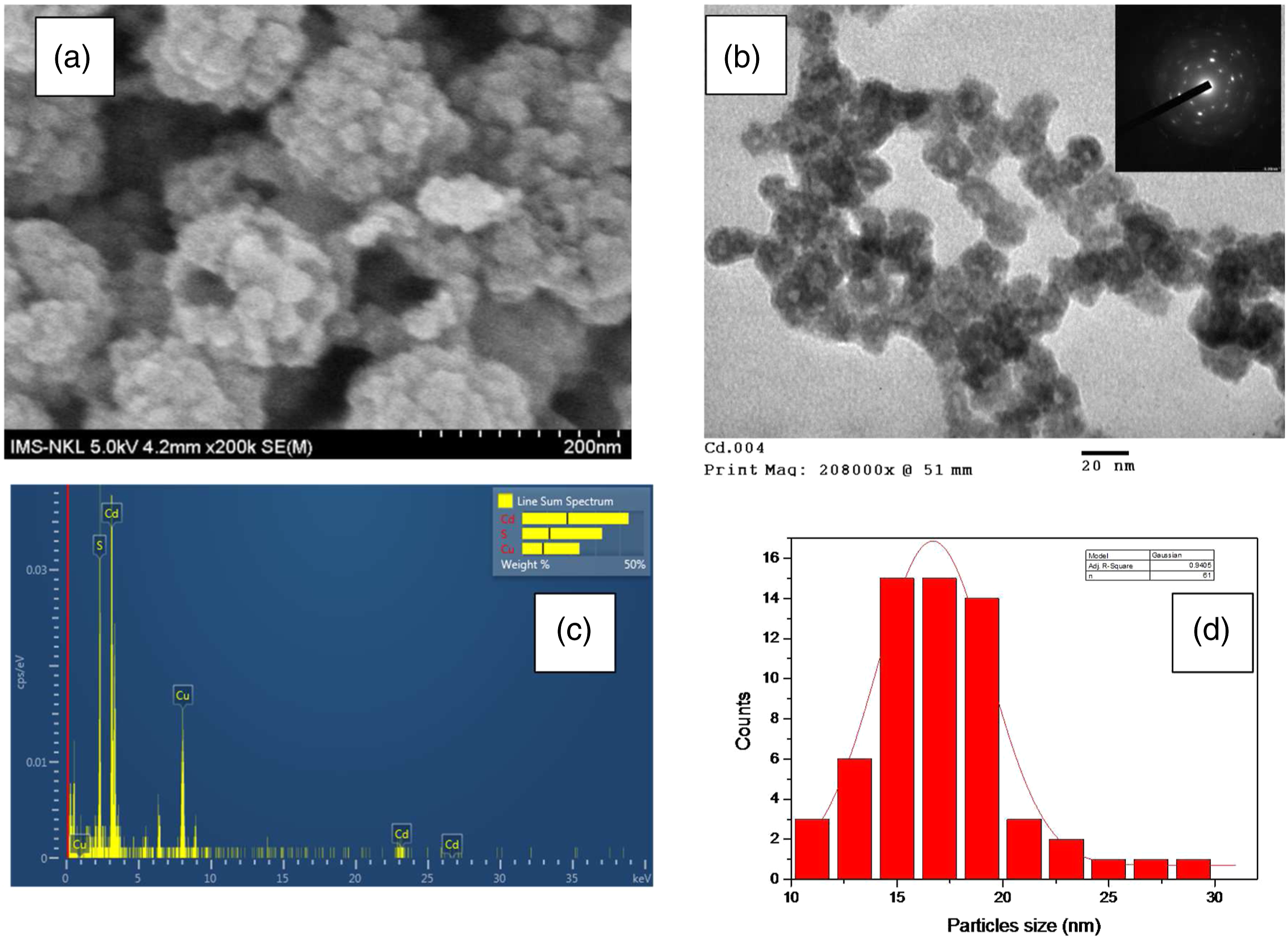
The kinetic of Cd ion removal confirmed the Cd loss during the reaction in the cathode of BES. After 21 days of experiment, the concentration of Cd ions in the supernatant of the cathodic solution reduced from 0.95 mM to 0.88 mM for BES and remained at 1.01 mM for Control (Figure 2). In addition, thiosulfate concentrations in the supernatant of the cathodic solution at the end of the experiment were 4.3 and 4.7 mM for BES and Control, respectively. Thus, the amount of thiosulfate removal exceeded the amount of Cd(II) removal, enhancing the precipitation of CdS in the cathode. The electron from electrode was donated to either oxygen or thiosulfate in the cathodic solution via the equations.1–3,30,31 The considerable amount of H2S gas was leaked into the headspace of the cathode and surrounding environment (H2S gas could be smelled when sampling the cathodic solution), and aqueous H2S was not able to be detected (ESI.table). The pH (7.09) and oxidation-redox potential (133.6) (ESI.table) were not favored for the aqueous phase of H2S in the solution according to the Pourbaix Diagram for sulphur–water
30
Cd ion concentrations in the supernatant of cathodic solution in the nec_BES without Shewanella sp. HN-41 (Control) and the nec_BES inoculated with Shewanella sp. HN-41 (BES).


Previously, investigations in the CdS precipitation by Cd(II) and Na2S/H2S confirmed the formation of hollow (void) CdS nanoparticles.32,33 The hollow sphere of CdS-NPs has been synthesized with the assistance of poly-glycol 32 or chloride anion. 33 With the presence of poly-glycol, CdS hollow spheres of approximately 25 nm average diameter and 5 nm shell thickness were formed by the precipitation method with CdSO4 and Na2S in benign conditions. The authors found that the poly-glycol had a significant influence on the formation of the CdS hollow spheres because without poly-glycol only solid particles were formed. When CdCl2 and H2S were used for the formation of CdS, Van Hövell et al. (1989) found chloride played an exceptional role in the precipitation of CdS. Authors found chloride present at the grain boundaries inside the particles, and during the formation of CdS crystallites, the chloride promoted the formation of particles as well as interfered in the aggregation of the crystallites into the single particle. 33 In our experiment, the chloride was at a low concentration (∼2 mM) but still influenced the formation of hollow nanoparticles of 17 nm and the open and void aggregates of spheres. The fact that chloride was not detected in the particles (or aggregates) was due to the washing step with de-ionized water three times before analyzing by EDS.
It was interesting that the crystallinity of CdS was complex and mixed as shown in Figure 3. The XRD pattern of CdS showed the sharp diffraction peaks in the range of 20o<2θ<120o can be indexed as cubic (zinc blend) CdS (200) and (220) and hexagonal CdS (102), (110), (103), and (202), which all are in good accordance with ICDD (International Centre for Diffraction Data) pdf card numbers: 10–454 and 41–1049, respectively. The results were insistent with the finding by Van Hövell et al,
33
in which chloride promoted the mixed crystallites between hexagonal hollow CdS and cubic CdS. The authors also proposed a precipitation model for the formation of hollow sphere structure of CdS as the following: (i) CdS molecules are homogeneously precipitated, (ii) the nuclei then grow to single-phase (hexagonal or cubic) crystallites, and finally (iii) the crystallites are aggregated or cemented by continuing crystal growth or recrystallization into polycrystalline (mostly mixed-phase particles).
33
XRD pattern of CdS hollow particles synthesized after 21 days incubation.
The hollow sphere of CdS has been reported to be an extraordinary photocatalytic activity
34
and electro-generated chemiluminescence H2O2 sensor
32
; therefore, we investigated the UV-Vis absorption spectrum of the CdS nanoparticles. The absorption spectrum of CdS-NPs shows a shoulder peak at ∼ 460 nm, equivalent to the band gap energy of 2.69 eV based on the energy equation of quantum mechanics (Figure 4). Previously, Lopez-Cabana et al. (2011) reported the absorption edge for the bulk CdS was at 530 nm (2.34 eV). The authors also confirmed the absorption spectra of the nanocomposites demonstrated various blue-shifted absorption edges depending on sulphur contents (in the range of 519 nm (2.39 eV) to 485 nm (2.56 eV)), and it was due to the confinement of electronic states of the semiconductor.
35
It was also notified that hexagonal CdS epilayers on CdTe substrates demonstrated the first intensive excitonic emission at 485 nm at low temperature.
36
Therefore, the blue-shifted absorption of the CdS-NPs may be due to the effect of cubic CdS nanocrystals that showed the intensive excitonic emission in the range of 400 to 460 nm.
37
UV-VIS spectrum of CdS-NPs formed in the cathodic solution of nec_BES inoculated with Shewanella sp. HN-41.
Electron donation at the anode
The anode compartment contained the sterilized mineral medium bubbled with nitrogen gas to remove oxygen and was inoculated with Shewanella sp. HN-41. Only lactate was supplied into the medium as a sole substrate for providing energy source. Bacterial cells quickly consumed lactate substrate in the BES, meanwhile there was no change of lactate in the anodic solution of the Control (Figure 5). The lactate concentration decreased from 10 mM to 3 and 1.5 mM in the BES after two and four days of the experiment, respectively. On day 6th, the lactate in the anodic solution was not detected by HPLC, confirming that bacterial cells consumed all the substrates, and thereby, the lactate was added into the anode upto 10 mM after every 6 days to supplement the substrate for the cells. In addition to lactate reduction, the pH of the medium in the anodic solution of BES was changed from 7.67 to 7.54 after 6 days of incubation (Figure 5). Then the pH remained stable at 7.5 in BES until the end of the experiment, while the pH value of anodic solution in the Control was slightly changed from approximately 7.7 to 7.6 from day 0th to 21st. It indirectly confirmed that bacterial cells consumed the lactate and produced acidic environment in the anode. Thus, in the BES, the produced electron and proton were donated to electrode of the anode (which works as a final electron acceptor) and HEPES buffer, respectively. The pH of the BES anodic solution was decreased and stabilized at pH 7.5 as a consequence of the lactate oxidation to release H+(equation (4)) and buffering of HEPES in the medium Changes of lactate concentration (top) and pH (bottom) in anodic solution of nec_BES inoculated with Shewanella sp. HN-41 (BES) and nec_BES without Shewanella sp. HN-41 (Control).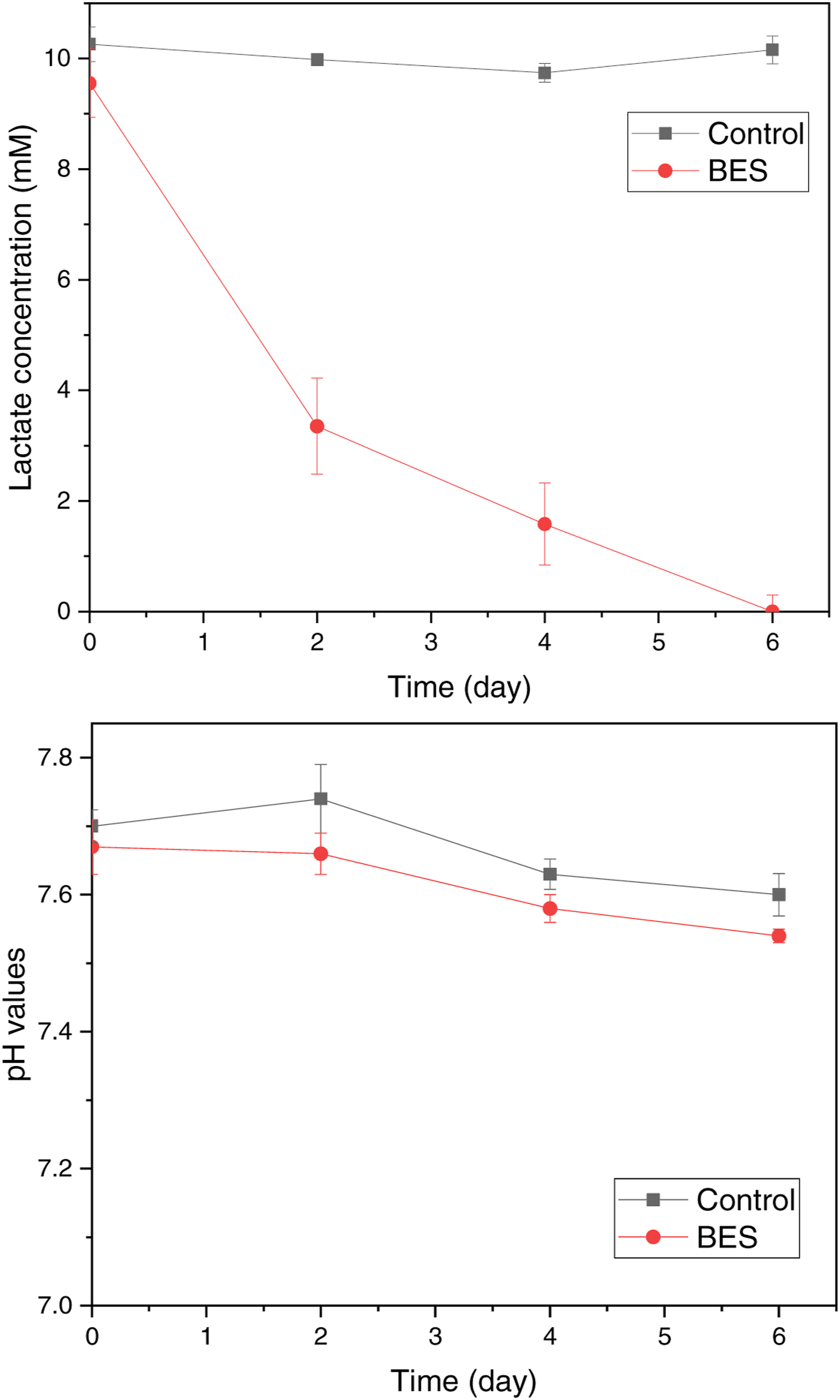

Several BESs operations were reported with Shewanella spp. as a model organism38,39 which was a facultative anaerobic bacteria. 40 In this study, the cells of the anaerobically grown Shewanella sp. HN-41 are electrochemically active and able to use lactate as an electron donor source as in the stoichiometric equation (4) and donating the electron to its terminal electron acceptor.28,29,41 A previous study reported Shewanella sp. strain HN-41 had the ability of extracellular electron transfer in microbial fuel cells (MFCs) fed with lactate or glucose. 42 In their conventional MFCs, the strain HN-41 used lactate as substrate to generate the maximum current density of 321.5 mA.m−2 in the single-chamber MFC and generated the maximum current density of 255.9 in the dual-chambers MFC. The strain HN41 secreted flavin mononucleotide (FMN), riboflavin, and traces of flavin adenine dinucleotide in MFCs, and it was proved that riboflavin and FMN played as electron mediators contributed to 25 folds increase in power density. The electron shutter carried electron produced from the cells to graphite electrode and, in its turn, the electrode transferred electron directly to the electron acceptors in the cathodic solution.
Conclusions
A new tool (nec_BES) for the synthesis of hollow sphere CdS-NPs was described in the investigation. Hollow CdS-NPs with the averaged size of 17 nm were formed in the cathodic solution and characterized with mixed crystallites of hexagonal and cubic phases. The formation of hollow nanoparticles and open void aggregates possibly resulted from the chloride and other anions in the cathodic solution. The blue shift in the absorption edge of produced CdS-NPs was possibly a potential property for the application in the optical and sensor technology. The synthesis of CdS-NPs via nec_BES proposed a facile and inexpensive tool for formation of other metals sulphide nanoparticles.
Footnotes
Acknowledgment
This research is funded by Vietnam National Foundation for Science and Technology Development (NAFOSTED) under grant number: 104.03-2016.45.
Authors contributions
For the experiment, authors (Thuong Thuong Lam, Canh Xuan Nguyen, and Cuong Tu Ho) were responsible for designing and constructing the system. Miss Lam was also operating and monitoring ion concentration in the system. Dr Youri Yang was responsible for analyzing lactate concentration in the media of anode. Mrs Hanh Thi Nguyen contributed to the analysis of SEM and TEM. Dr Quang LeDang was responsible for analyzing XRD data and revised the manuscript. Miss Thuong and Dr Cuong Tu Ho wrote the manuscript while Prof. Ji-hoon Lee and Prof. Hor-Gil Hur edited the manuscript.
Declaration of conflicting interests
The author(s) declared no potential conflicts of interest with respect to the research, authorship, and/or publication of this article.
Funding
The author(s) received no financial support for the research, authorship, and/or publication of this article.
Availability of data and material
The data and material for this work are available in my Google driver, if anyone is interested or concerned about the data, please feel free to contact with the corresponding author.