
Abstract
This study reports the performances of a single structured light-emitting diode (LED) devices based on polymer material poly(9,9-di-n-hexylfluorenyl-2,7-diyl) (PHF) mixed with various concentrations of perovskite oxide strontium titanate (SrTiO3) particles deposited as a composite PHF: SrTiO3 emitting layer. The performances of the single structured organic LED indium tin oxide (ITO)/PHF/aluminum (Al) device and the composite LED ITO/PHF: SrTiO3/Al devices were compared in terms of turn-on voltage and luminance intensity. By incorporating perovskite SrTiO3 particles into PHF emitting layer, the turn-on voltage of the device is significantly reduced from 11.25 V to 1.80 V and the luminance intensity increased from 57.7 cd/m2 to 609 cd/m2. The improvement of turn-on voltage and the electroluminescence spectrum of the composite devices were found to be dependent on the weight ratios of SrTiO3 content in the PHF emitting layer.
Introduction
In recent years, the development of organic light-emitting diodes (OLEDs) has been gaining great attention as researchers are searching for a novel approach to improve OLED performance in display systems and lighting sources. Although OLED performance has been stabilized and commercially developed, 1,2 the on-going research to discover new methods to enhance the OLED performance is still intense. OLED device performance is effectively determined by the organic emitting materials, such as photoluminescence (PL) polymers and small molecules. The choices of emitting materials in OLED’s device fabrication could provide the desired light-emitting color as well as the device’s efficiency and stability. 3 One of the approaches to improve OLED’s performance is to synthesize new materials, which requires advanced chemical skills. Alternatively, researchers use commercially accessible OLED material polymers and combine them to form composites with inorganic substances, thereby modifying their PL characteristics. In 2018, David’s group reported that improved poly[2-methoxy-5-(2-ethylhexyloxy)-1,4-phenylenevinylene](MEH-PPV)/zinc oxide composite device resulted in a luminance intensity of 2.9 × 10 5 cd/m 2 at 10 V, exhibiting higher electroluminescence (EL) intensity compared to pristine MEH-PPV. 4 Liu et al. 5 reported a maximum luminance of 9.7 × 10³ cd/m2 and external quantum efficiency of 4.4% of composite 3,5-bis(carbazol-9-yl)pyridine and copper iodide as an emissive layer in OLED. Nayak and Choudhary reported that the poly(methyl methacrylate), (PMMA)-zinc sulfide nanocomposites showed the increased pattern of PL spectra intensity of blue, green, and yellow bands with shorter decay time and improved color purity. 6
One of the potential inorganic materials that could be blended with polymer materials is perovskite. Perovskite-structured materials have been extensively studied due to their extraordinary optoelectronic characteristics, such as synthetic bandgap tunability, high absorption coefficient, good photoconductivity, and long charge carrier diffusion length with higher lifetimes, 7 –9 making perovskite materials great for diverse applications, including light-emitting diode (LED), 10 –12 solar cells, 13 –16 photocatalysis, 17 lasers, 18 and photodetectors. 19 According to recent research, the use of lead (Pb) halide perovskite structured materials in LED devices has been reported to deliver better LED performance. 20,21 However, the instability and toxicity of Pb-based perovskite are highly debated as risking human health and the ecosystem. Therefore, perovskite oxide, which has excellent photoluminescent properties, such as strontium titanate (SrTiO3) 22,23 and barium titanate (BaTiO3), 24,25 could be the derivatives to replace Pb-based perovskite in fabricating LED devices. It is an interesting alternative that incorporates perovskite oxide in the LED-emitting layer as a composite material.
In this study, we fabricate LEDs of composites poly(9,9-di-n-hexylfluorenyl-2,7-diyl) (PHF) with inorganic perovskite oxide SrTiO3 particles (Figure 1). PHF is a stable blue-emitting polyfluorene polymer but the efficiency of the OLED device using this organic material is low. Therefore, by incorporating perovskite SrTiO3 particles in the PHF-emitting layer, this study is expected to enhance the performance of composite polymer perovskite, PHF: SrTiO3 LED devices.
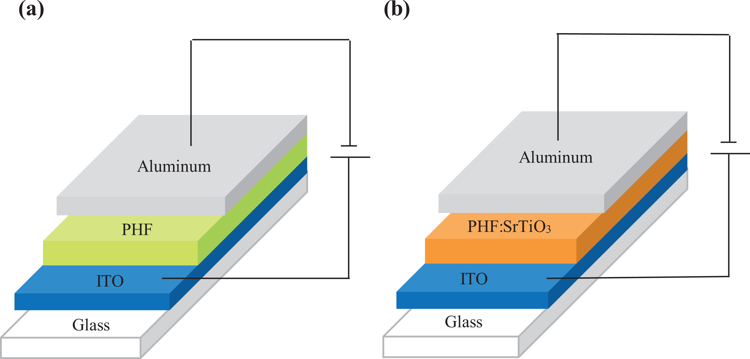
(a) OLED ITO/PHF/Al device and (b) composite ITO/PHF: SrTiO3/Al device. OLED: organic light-emitting device; ITO: indium tin oxide; PHF: poly(9,9-di-n-hexylfluorenyl-2,7-diyl); Al: aluminum; SrTiO3: strontium titanate.
Experimental
Materials and method
PHF as a host emissive material organic blend for the composite device was purchased from Sigma-Aldrich, United States. Perovskite oxide SrTiO3 powder was synthesized at 180°C temperature for 6 h using an alkali hydrothermal process. 26 The SrTiO3 solution was prepared by dissolving 14 mg of SrTiO3 powder into 1 mL of absolute ethanol and stirred for 6 h, which resulted in a milky colored solution. Meanwhile, 14 mg of PHF powder was dissolved in 1 mL chloroform to form the basic solution. To prepare the polymer-perovskite solution, five variations of the SrTiO3 weight ratio in percentages 10%, 20%, 30%, 40%, 50% to PHF weight were separately added into the basic solution. All of these solutions were stirred at room temperature for 20 h to ensure that the composite solution is completely dissolved and homogeneous.
OLED device fabrication
ITO substrates were ultrasonically washed, sequentially, in detergent solution, deionized water, isopropanol, acetone, and ethanol for 15 min each to clean and remove any impurities on the ITO surface. Twenty microliters of PHF solution was spin-coated onto the ITO substrate at 3000 r/min for 30 s in a fume hood. The process is repeated for each composite PHF:10–50% weight ratio of SrTiO3 content to PHF weight. The thin films were then heated at 70°C for 30 min in a vacuum oven to remove the residual solution. Subsequently, the thin films were loaded into the vacuum evaporation chamber for cathode aluminum deposition. The aluminum pellets in the molybdenum crucible were deposited at the chamber pressure of 2.5 × 10⁻⁶ Pa at a rate of 2 Å/min. The active area and thickness of the aluminum cathode prepared were 0.19625 cm2 and 150 nm, respectively. A single structure layer of LED devices has been fabricated, as shown in Figure 1, labeled as ITO/PHF/Al and ITO/PHF: SrTiO3/Al. The PHF-based OLED device acts as a controlled device while PHF: SrTiO3 composite devices are labeled according to the weight ratio of SrTiO3 content (10–50%) to PHF weight.
OLED characterization
The optical absorption and diffuse reflectance measurements were carried out using a Lambda 900 Perkin Elmer UV-Vis spectrophotometer to determine the bandgap of the PHF (Figures S1 and S2 in Supplemental Material) and SrTiO3 thin films (Figure S5 in Supplementary Material). A cyclic voltammetry experiment was performed to estimate the highest occupied molecular orbital (HOMO) and the lowest unoccupied molecular orbital (LUMO) of the PHF (Figure S3 in Supplementary Material). The PHF and PHF: SrTiO3 thin-film thickness were measured using the Veeco Surface Profiler DEKTAK 150 model. The PL spectra of the composite thin films were recorded using an Edinburgh Instrument FLSP920 spectrophotometer. The current density–voltage (J-V) curve was obtained using a Keithley 238 SMU (Source Measurement Unit) that is equipped with Interactive Characterization Software (Keithly). Meanwhile, EL spectra, luminance, and color measurements were obtained using the HR2000 Ocean Optic Spectrophotometer and fully controlled using the OOIIrrad-C software (SpectraSuite). All experiments were performed at room temperature as perovskite SrTiO3 cubic phase exists at room temperature.
Results and discussion
Current density–voltage (J-V) measurement
Figure 2 shows the curve of current density (J) versus voltage (V) of the OLED structure ITO/PHF/Al (inset) and composite device structure ITO/PHF: SrTiO3/Al. These J-V curves were represented in a log scale on the current density plane and created a tangent shortcut at J = 1 mA/m2 to determine the precise turn-on voltage, V on. 27
The PHF: SrTiO3 composite devices showed different J-V curve shape, as compared to the slow current rise of the ITO/PHF/Al device. The J-V curve of ITO/PHF/Al device is similar to the common J-V curve of polymer and small organic molecules OLED devices. It can be matched with the charge transport theory of space charge limited current. 28 In addition, when the applied voltage achieved at a certain turn-on voltage values, the J-V curve shape of ITO/PHF: SrTiO3 was seen to have increased abruptly in current density from 1 mA/m2 to more than 10 mA/m2. This is probably due to the assembly of PHF: SrTiO3 composite’s bulk heterostructure as well as the interface between the energy level of both materials, which promote the injection of charge carriers into the device.

Current density–voltage (J-V) curves of ITO/PHF: SrTiO3/Al composite devices with a variation of the weight ratio of SrTiO3 content (10–50%) to PHF weight. Inset is the J-V curves of OLED ITO/PHF/Al device. OLED: organic light-emitting device; ITO: indium tin oxide; PHF: poly(9,9-di-n-hexylfluorenyl-2,7-diyl); Al: aluminum; SrTiO3: strontium titanate.
Table 1 presents the relationship between thickness and turn-on voltage for all devices. As we increased the weight ratio of SrTiO3 into PHF, the thickness of the composite devices increased, leading to the turn-on voltage to increase. However, the turn-on voltage of all PHF: SrTiO3 composite devices was observed to have increased in performance as the V on was decreased to a minimum 1.80 V compared to the PHF device, 11.25 V. The discussion on energy level interface between PHF: SrTiO3 and the reduced turn-on voltage value of the composite devices are discussed in the latter part of this article.
The thickness of thin-film and turn-on voltage for composite ITO/PHF: SrTiO3/Al devices with a variation of the weight ratio of SrTiO3 content (10–50%) to PHF weight.

ITO: indium tin oxide; PHF: poly(9,9-di-n-hexylfluorenyl-2,7-diyl); Al: aluminum; SrTiO3: strontium titanate.
EL spectra measurement
EL spectra of PHF and PHF: SrTiO3 composite devices under maximum luminescence are compared in Figure 3. It is observed that all PHF: SrTiO3 composite devices have higher luminance intensity than the PHF spectrum and yielded broad EL spectra in a range of lower energy bandgap.

Electroluminescence spectra at the maximum luminance (L max) of ITO/PHF: SrTiO3/Al composite devices with a variation of the weight ratio of SrTiO3 content (10–50%) to PHF weight. ITO: indium tin oxide; PHF: poly(9,9-di-n-hexylfluorenyl-2,7-diyl); Al: aluminum; SrTiO3: strontium titanate.
By incorporating SrTiO3 particles into the PHF emitting layer, the recorded EL intensity was increased to a maximum luminance value of 609 cd/m2, as compared to the PHF device, 57.7 cd/m2 (Table 2). The increase in luminance intensity is caused by overlapping of molecular orbitals of PHF and SrTiO3, which assist charge carriers to be transferred in the composite devices. The recorded EL intensity was observed to have the same increased pattern of the PL spectra intensity of PHF: SrTiO3 thin films, 29 which is shown in Figure 4. The PL spectra of the PHF and PHF: SrTiO3 composite thin films have two distinct peaks at 428 and 447 nm, except PHF:50% SrTiO3, which only have one distinct peak at 449 nm. Meanwhile, the peak position of composite ITO/PHF: SrTiO3/Al EL spectra is different in between the wavelength range of 555–743 nm. The behavior of redshifting peak transition happened because the PHF localized state density is increased when PHF is blended with SrTiO3 particles making the bandgap of the PHF becomes smaller, thus leading to higher wavelength. When polymer PHF is mixed with perovskite SrTiO3, the bandgap of the PHF could change due to the formation of interfaces and interaction of energy band between PHF HOMO-LUMO and SrTiO3 valence band (VB)–conduction band (CB). The blending process will form new bonds between these two materials and overlapping of the molecular orbitals will be increased. 30 The process will either donate or accept the electrons and eventually will alter the Fermi level of polymer PHF. In the case of SrTiO3, the perovskite will donate electrons to replace the empty orbital space at LUMO of PHF. This situation could narrow the distance between the HOMO and LUMO of PHF, thus lowering the PHF bandgap. The other reason PHF bandgap becomes smaller is that the dopant size is larger than the host component. The size of the SrTiO3 particles used in the thin-film devices is ranging around 140–150 nm, while PHF particles are less than 50 nm. Supported by the quantum confinement theory, as the particle sizes reach a larger scale, every particle is made up of a high number of atoms and molecules, thus leading to an increased number of orbitals overlapping and the width of the energy band gets wider. 31 This will cause a decrease in the energy gap of the HOMO and LUMO of PHF, thus explaining why the PHF bandgap became smaller and the redshifting transition happened.
Electroluminescence peak wavelength, photoluminescence peak wavelength, maximum luminance, CIE coordinates and color at L max for ITO/PHF: SrTiO3/Al composite devices with a variation of the weight ratio of SrTiO3 content (10–50%) to PHF weight.

ITO: indium tin oxide; PHF: poly(9,9-di-n-hexylfluorenyl-2,7-diyl); Al: aluminum; SrTiO3: strontium titanate; PL: photoluminescence; EL: electroluminescence.
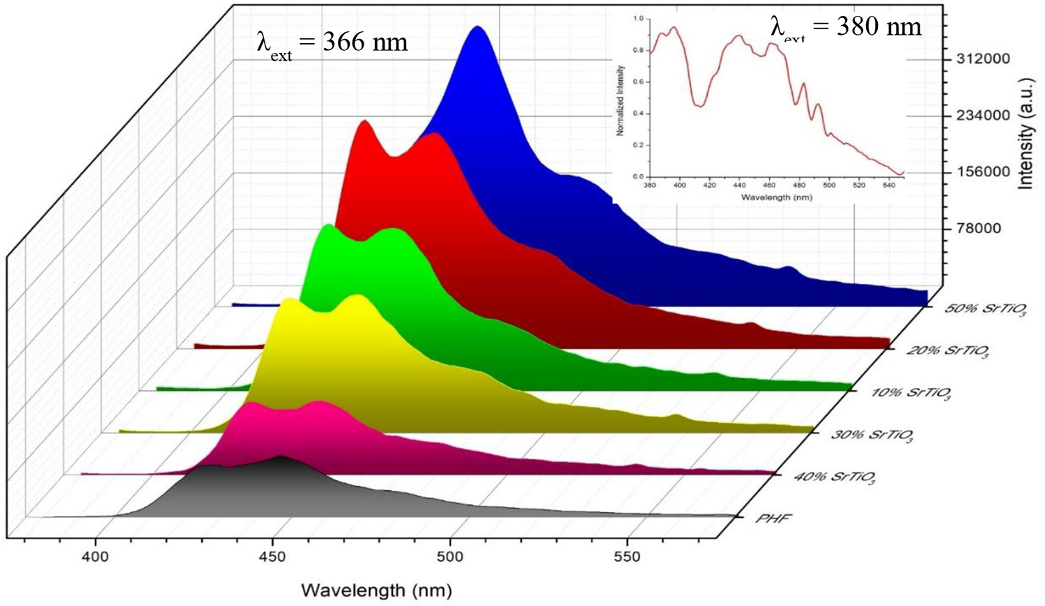
Photoluminescence spectra of the PHF and the PHF: SrTiO3 composite thin films with a variation of the weight ratio of SrTiO3 content (10–50%) to PHF weight. Inset is PL spectrum of the SrTiO3 thin film, reproduced with permission. 29 Copyright 2016, Elsevier.
The EL spectra are recorded at maximum brightness condition and matched with the standard CIE color coordinates, as plotted in Figure 5. All PHF: SrTiO3 composite devices have the color changed between a mixture of yellow-orange and yellow, as compared to green color emitted from the PHF device. This color change can be seen in the widening of the EL spectrum of these composite devices to a higher wavelength.

Coordination CIE at luminance maximum for ITO/PHF: SrTiO3/Al composite devices with a variation percentage of the weight ratio of SrTiO3 to PHF weight: (a) PHF, (b) PHF:10% SrTiO3, (c) PHF:20% SrTiO3, (d) PHF:30% SrTiO3, (e) PHF:40% SrTiO3, and (f) PHF:50% SrTiO3. ITO: indium tin oxide; PHF: poly(9,9-di-n-hexylfluorenyl-2,7-diyl); Al: aluminum; SrTiO3: strontium titanate.
Operation mechanism of composite ITO/PHF: SrTiO3/Al device
The discussion of composite ITO/PHF: SrTiO3/Al devices operating mechanism is closely associated with the energy level diagram. By referring the analysis method for obtaining HOMO-LUMO of PHF and SrTiO3 CB-VB from the previous study, 29 the energy level diagram of PHF and SrTiO3 thin films is schematically described in Figures S4 and S6 in Supplemental Material, respectively. Since PHF and SrTiO3 were blended in a layer, there are two possible configurations of the formation of the devices, including ITO/SrTiO3/PHF/Al and ITO/PHF/SrTiO3/Al. Figure 6 shows the process of charge carrier injection, the formation of exciton and emission of light when the device is applied with forward bias voltage, V > Vbi. Vbi is known as built-in voltage and is created by depletion of the interfacial area of electrons and holes in n and p regions.
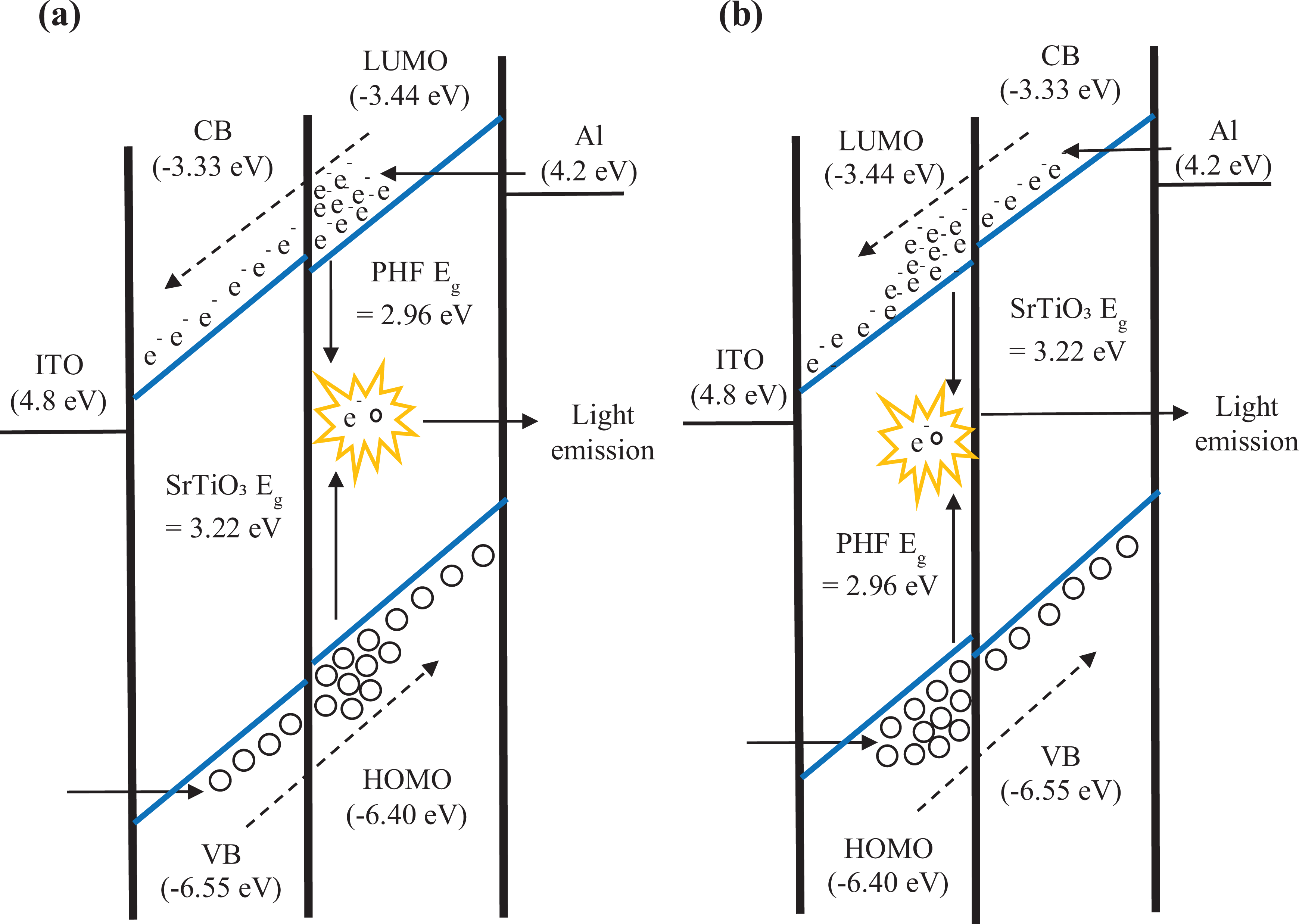
The energy levels in composite device structure given forward bias voltage, V > Vbi, with the configuration (a) ITO/SrTiO3/PHF/Al and (b) ITO/PHF/SrTiO3/Al. ITO: indium tin oxide; PHF: poly(9,9-di-n-hexylfluorenyl-2,7-diyl); Al: aluminum; SrTiO3: strontium titanate.
Figure 6(a) shows the first configuration of the composite device, where electrons are injected into the PHF and subsequently transport the electrons throughout the layer to SrTiO3. The movement of electrons experienced some sanction at the PHF-SrTiO3 interface because the CB of SrTiO3 is slightly higher than the LUMO level of PHF. As a result, the electrons are accumulated in the PHF layer at the PHF-SrTiO3 interface. At the same time, holes are injected through the SrTiO3 layer and are moving in the opposite direction. The movement of holes in the SrTiO3 layer is unblocked due to the VB of SrTiO3 being slightly lower than the HOMO level of PHF. Electrons that gathered at the interface of these two materials will combine with holes to form excitons and then turn decays back to emit the energy in the form of a light beam. Exciton formation can also occur throughout the PHF layer as well.
In the second configuration as in Figure 6(b), electrons are injected into SrTiO3 and easily surpassed the energy barrier at the LUMO level of PHF as it is lower than the CB of SrTiO3. Subsequently, holes are injected into the HOMO level of PHF and drift to the interface area of PHF-SrTiO3. In this instance, the movement of holes is blocked due to the energy barrier in the VB of SrTiO3 is low. The holes will be accumulated at the interface between these two materials, which then forming excitons with the electrons that were injected from SrTiO3. In addition, the emission will occur within the materials.
Based on Table 1, we have observed that the value of V on is much dependent on the percentage weight ratio of SrTiO3 content and PHF that in turn affecting the layer thickness of the devices. The increasing weight ratio percentage of SrTiO3 leads to thicker layer devices that eventually contribute to higher turn-on voltage. This is attributed to the injection of charge carriers into the device that is affected by external electric fields E = V/d, which is highly dependent on the thickness d of the emitter layer. 32 The abrupt increase in current density at the J-V curve of the composite devices could be ascribed by the assembly of the PHF: SrTiO3 composite, whereby the interface of both material’s energy level facilitates the injection of charge carriers into the device. Based on the first configuration of the energy level diagram in Figure 6(a), holes in SrTiO3 are easily transferred into PHF as VB of SrTiO3 is slightly lower than HOMO of PHF. Meanwhile, in the second configuration of the energy level diagram, Figure 6(b), electrons that are injected through SrTiO3 are easily transferred into PHF as CB of SrTiO3 is slightly higher than LUMO of PHF. Both of these configurations contribute to the mobility of charge carriers in the devices. With higher mobility of charge carriers, faster radiative recombination process would likely to occur to release energy by the emission of excitons. Thus, accumulative electrons and holes at the interface of both energy materials will contribute to faster excitons recombination, which could lower the V on. In comparison to the PHF device, electrons from the cathode are injected through the PHF layer and need to overcome the high resistance of PHF thick layer to reach the anode. Higher energy is needed to cross the interface barrier of PHF, therefore leading to a higher V on of the PHF device.
The presence of the perovskite oxide, SrTiO3, in the PHF has improved the luminance of the original device. The PL spectrum shows that the light emission is expected to occur in PHF materials. Exciton formation increased at the interface area of PHF: SrTiO3, where there are many overlaps of molecular orbitals of PHF and SrTiO3, which can facilitate electron transfer from semiconducting SrTiO3 to PHF polymer. The increased overlapping of these orbitals at the interface resulted in more excitons being formed, which indirectly increases the luminance of the composite devices. For the PHF:50% SrTiO3 device, surface interaction between these two materials is likely to be the highest. As SrTiO3 has high energy level, part of the excited electrons in SrTiO3 has transferred the energy to PHF, making this composition with the highest intensity of luminance. Yet, there are still PHF: SrTiO3 composite devices that contained a high percentage of SrTiO3 but demonstrated a rather low luminance. This matter is closely related to the homogeneity of the PHF: SrTiO3 composition in the emitting layer. In the process of mixing these two materials, distribution of the polymer and perovskite materials on the thin film is randomly dispersed. Since the SrTiO3 particles used for the thin films are ranging between 140 and 150 nm in size, particles at this nanometer range tend to aggregate more because of their interparticle distances. 33 Moreover, at a certain ratio of the perovskite composition, the strong van der Waals force attracted the polymer and perovskite nanoparticles to each other, which resulted in inhomogeneous aggregation and dispersion, thus could reduce the interface area between these two materials.
By comparing the PL and EL spectrum, all the radiation peaks shown are mainly taken by PHF material. However, we observed that the EL spectrum of the PHF: SrTiO3 composite devices experienced a widening spectrum toward red wavelengths, thereby causing changes in color. The redshifting occurred because the energy level and the energy gap of the PHF material become smaller from the original when blending with SrTiO3. In the composite material, the SrTiO3 atom will come in contact with PHF atom. As SrTiO3 ratio composition in the PHF is increasing, SrTiO3 atom side induced strain to the PHF atom and lead to changes in the interatomic distance between SrTiO3 and PHF. These adjacent molecules are likely to interact with each other through electronic orbital overlapping. When overlapping molecular orbital happens, the distance between the HOMO and LUMO of PHF will be narrower. Therefore, the narrow energy level makes electrons’ movement from the lowest state of PHF LUMO to the highest state of PHF HOMO faster, so that the composite device exhibits higher electrical conductivity than the control PHF device. So, there will be a change in the spectrum of absorption toward a higher wavelength or red region.
Conclusions
This study demonstrates that the incorporation of perovskite oxide SrTiO3 particles into the OLED-based polymer PHF increases the performance of the device by reducing the turn-on voltage and increasing the luminance intensity. However, the EL spectrum is shifted to a higher wavelength that causes color changes.
Supplemental material
Supplemental Material, sj-pdf-1-nax-10.1177_1847980420987774 - On the performance of polymer-inorganic perovskite oxide composite light-emitting diodes: The effect of perovskite SrTiO3 additives
Supplemental Material, sj-pdf-1-nax-10.1177_1847980420987774 for On the performance of polymer-inorganic perovskite oxide composite light-emitting diodes: The effect of perovskite SrTiO3 additives by Ummi Kalsom Noor Din, Muhamad Mat Salleh, Tengku Hasnan Tengku Aziz, Ahmad Rifqi Md Zain, Mohd. Ambri Mohamed and Akrajas Ali Umar in Nanomaterials and Nanotechnology
Footnotes
Declaration of conflicting interests
The author(s) declared no potential conflicts of interest with respect to the research, authorship, and/or publication of this article.
Funding
The author(s) disclosed receipt of the following financial support for the research, authorship, and/or publication of this article: This work was supported by the Malaysian Ministry of Education (MOE) and Universiti Kebangsaan Malaysia under the research grant no. LRGS/2015/UKM-UKM/NanoMiTe/04/04 and GGPM-2018-017.
Supplemental material
Supplemental material for this article is available online.
References
Supplementary Material
Please find the following supplemental material available below.
For Open Access articles published under a Creative Commons License, all supplemental material carries the same license as the article it is associated with.
For non-Open Access articles published, all supplemental material carries a non-exclusive license, and permission requests for re-use of supplemental material or any part of supplemental material shall be sent directly to the copyright owner as specified in the copyright notice associated with the article.