Anomalous scattering effects (invisibility, superscattering, Fano resonances, etc) enabled by complex media and metamaterials have been the subject of intense efforts in the past couple of decades. In this article, we present a full analysis of the unusual and extreme scattering properties of an important class of complex scatterers, namely, gyrotropic cylindrical bodies, including both homogeneous and core–shell configurations. Our study unveils a number of interesting effects, including Zeeman splitting of plasmonic scattering resonances, tunable gyrotropy-induced rotation of dipolar radiation patterns as well as extreme Fano resonances and non-radiating eigenmodes (embedded eigenstates) of the gyrotropic scatterer. We believe that these theoretical findings may enable new opportunities to control and tailor scattered fields beyond what is achievable with isotropic reciprocal objects, being of large significance for different applications, from tunable directive nano-antennas to selective chiral sensors and scattering switches, as well as in the context of nonreciprocal and topological metamaterials.
The emerging area of topological electromagnetics and photonics is stimulating renewed interest in natural and artificial gyrotropic (meta)materials to achieve anomalous propagation effects,1,2 including unidirectional, defect-immune, wave-guiding structures, and robust radiating systems.3–6 Relatively less attention has instead been devoted to gyrotropic scattering systems and their unusual scattering effects.7,8 Indeed, several of the conventional symmetries of scattering systems (time-reversal symmetry, angular symmetries of the radiation pattern, etc) are broken when certain materials are biased by a static magnetic field (or other quantities, e.g. angular momentum,9,10 that mimic the effect of a magnetic bias). For example, in a biased plasma, magneto-optic effects are due to the interaction of a harmonic electric field with free electrons in circular motion due to the applied static magnetic bias, which alters the usual plasma-like response of a gas of free electrons. As a result, the electric permittivity becomes a non-symmetric non-diagonal tensor, whose off-diagonal elements (proportional to the applied magnetic bias) are responsible for several important nonreciprocal effects, including the well-known Faraday rotation.11 The properties of gyrotropic media may open novel and unexplored possibilities to control and tailor the scattering response of material bodies for several applications, including cloaking, sensing, tagging, filtering, and so on.
Within this context, this work offers a complete analysis of scattering from individual gyrotropic wires and core–shell configurations. In particular, our goal is to elucidate the different resonant effects that arise when a nonzero bias is applied to the scatterer, with particular focus on the spectral splitting of resonances (Zeeman effect),12,13 the ability to modify and rotate the dipolar scattering pattern, and the connection of these results with recent investigations on Fano resonances14 and embedded eigenstates.15–18 The designed scatterers may also serve as meta atoms for nonreciprocal and topological metasurfaces and metamaterials, tunable and reconfigurable by varying the biasing field.
Single gyrotropic rod
Mathematical formulation
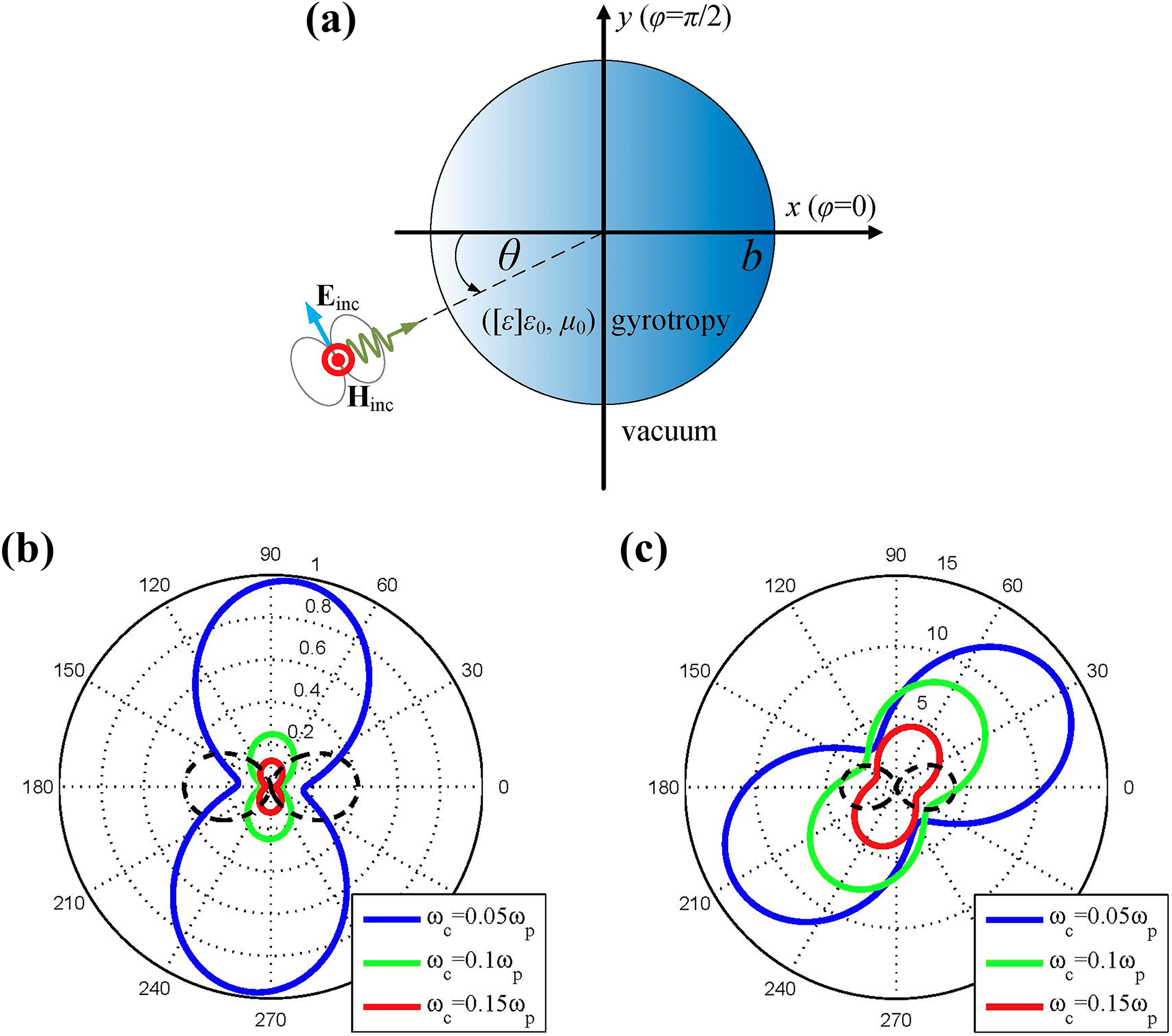
Consider an infinite wire with circular cross section of radius b filled with a generic gyrotropic material. In Cartesian coordinates (x, y, z), defined in Figure 1(a), the relative permittivity tensor of the gyrotropic medium is11
(a) A gyrotropic rod of radius b is excited by an incident TEz plane wave propagating along the direction defined by the angle θ. (b and c) Scattering patterns p(ϕ) of the rod (θ = 0°) for several cyclotron frequencies , at the frequency of maximum pattern rotation given by equation (7), for (b) and (c) . Black dashed lines indicate the corresponding scattering patterns in the unbiased case (). All results are obtained by exact Mie-theory calculations.
The scatterer is illuminated by a plane wave traveling in the x − y plane, forming an angle θ with the +x axis, with transverse-electric polarization with respect to the cylinder axis (TEz wave, with unitary amplitude 1 A/m), so that the wave “feels” the dielectric anisotropy of equation (1). A time-harmonic dependence is assumed for all field quantities and suppressed. While our derivation is general, we will focus our analysis on scatterers that are electrically thin, namely, . In this article, the symbols k0, η0, and c denote the free-space wavenumber, wave impedance, and speed of light, respectively, and ω is the oscillation frequency. The ideal permittivity model (1) can be realized as a cold plasma magnetized by a static magnetic field along the z axis. In this case, the elements of the permittivity tensor are frequency-dispersive and, in the lossless limit, are given by Bittencourt19
where ωp is the plasma frequency and ωc the cyclotron frequency proportional to the magnetic bias.
For a given material, the quantities can be controlled by two variables: the operational frequency and the cyclotron frequency normalized by the plasma frequency ωp of that material. The rod exhibits plasmonic features () for , which is the frequency range of interest for our analysis. For typical gyrotropic materials (e.g. bismuth iron garnet or n-doped indium antimonide under magnetic bias), the amplitude of the off-diagonal permittivity elements εg (strength of nonreciprocity) is typically two orders of magnitude smaller than the diagonal elements εt (e.g. see Fang’s work20), which is however sufficient to observe relevant magneto-optic effects in suitably designed configurations.
Despite the anisotropic properties of the cylinder, for a TEz normally-incident plane wave, Maxwell equations can be decoupled; therefore, the radial profile of the canonical Helmholtz-equation solutions, inside the gyrotropic medium, is a linear combination of , where are the Bessel and second-kind Hankel function of u th order ( azimuthal dependence),7 and the effective permittivity of the gyrotropic material is defined as . The corresponding cylindrical coordinate variables are denoted by . As usually done, the scattered field by the wire into free space can be represented as a discrete sum of cylindrical harmonics, and, after imposing the necessary boundary conditions, we obtain the scattering coefficients Su as follows
where .
The simplicity of this solution is partially related to the invariance of the permittivity tensor with respect to Cartesian/cylindrical transformations, which would not be the case if the two diagonal elements of equation (1) were not equal.21 The power scattered by the rod, normalized by the incident power (per unit length of the z-axis) , corresponding to the aperture of width 2b (equal to the cylinder diameter), is found to be equal to . We can also define the radiation pattern p(ϕ) of this scatterer as .
Thin-wire approximation
Since we are mainly interested in the role of a gyrotropic rod as a small scatterer or meta-atom, we assume and apply the well-known quasi-static dipole approximation.22,23 In this regime, we retain only the monopolar (omnidirectional) term (u = 0) and the dipolar terms () of the cylindrical harmonic expansion of the scattered field (corresponding to two circularly polarized dipoles of opposite helicity), which are the dominant scattering contributions in most cases of interest. Then, for observation points in the far-field region (), one can write , using a large-argument approximation of the Hankel function.24
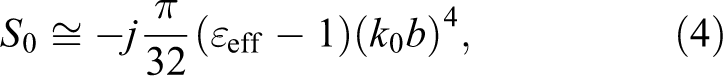
By approximating the monopololar and dipolar scattering coefficients, given by equation (3), for small electrical size , we obtain
Note that, in this regime, the dipolar coefficients are significantly larger than the monopolar term S0, due to the different dependence on the scatterer electrical size . Physically, such a difference is attributed to the electric nature of the obstacle (it constitutes a spatial discontinuity for the permittivity) combined with the magnetic nature of the excitation ( parallel to the axis of the infinite cylinder). It should also be stressed that S0 is almost purely imaginary and almost purely real (for a lossless medium, , the residual imaginary part is purely due to radiation loss). Most importantly, we notice that the magnetic bias makes the dipolar coefficients and different, whereas in the reciprocal case with no bias, that is , they are equal in magnitude and opposite . The fact that this degeneracy is lifted by breaking reciprocity (by biasing the system with a quantity that is odd under time reversal) is responsible for a number of interesting scattering effects as discussed in the next sections.
Maximal rotation of the scattering pattern
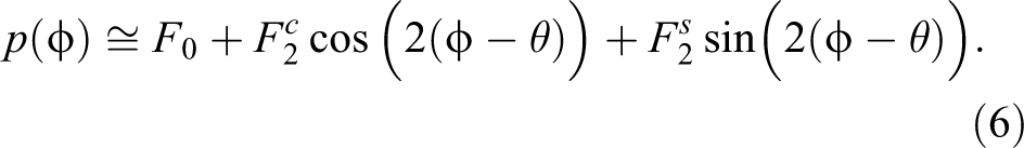
Under the aforementioned thin-wire assumption, it is possible to show that the radiation pattern , as defined above, takes the following form with real coefficients
The first term gives the omnidirectional monopolar response, and the second term is the conventional dipolar radiation pattern corresponding to an electric dipole normal to the direction of the incident wave (parallel to the y-axis for ), determined by the separation of charges in the scatterer by the incident electric field. Interestingly, the third term, which is absent in the unbiased (reciprocal) case, corresponds to the radiation from an electric dipole parallel to the incidence direction (parallel to the x-axis for ). This term arises as a result of the electrons’ circular motion (cyclotron motion) due to the static magnetic bias, which, combined with the harmonic electric field, forces the electron to accumulate and oscillate on an axis tilted to the right/left with respect to the y axis (for ), creating a horizontal (x-oriented) component of the induced dipole. In other words, such a term expresses the influence of the gyrotropy on the scatterer’s response, which leads to a rotation of the radiation pattern as further discussed below.
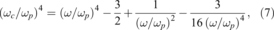
Maximizing such a pattern rotation, making the effect of the third term in equation (6) substantial, is rather counterintuitive since the dipolar response of the structure would become orthogonal to the one expected from its excitation. A suitable metric for this effect is the ratio of the (squared) amplitude of the odd function in equation (6) over the sum of the (squared) amplitudes of the even functions, that is, . For a given , the condition to maximize this quantity with respect to reads
which can be satisfied only for . As an aside, we note that, at the frequency , the permittivity of the gyrotropic material is in the unbiased case, which corresponds to the condition for localized surface-plasmon resonance in a subwavelength cylinder.25,26
In Figure 1(b) and 1(c), we show the radiation patterns (for incidence angle ) of a gyrotropic cylinder for various cyclotron frequencies , at operational frequencies that give maximal rotation according to equation (7). In Figure 1(b), we consider an ultrathin wire with (λp is the free-space wavelength at the plasma frequency ωp). Rather remarkably, as the cyclotron frequency is increased, the scattering pattern indeed tends to the pattern of a horizontal (parallel to the x-axis) electric dipole. This fact implies suppression of the conventional dipolar term in equation (6), which becomes much smaller than (a small monopolar term may still be present). As far as the scattered power is concerned, the overall scattering is weak since , and it decreases as the induced dipole becomes more and more tilted with respect to the unbiased case (denoted with black dashed lines). In this context, we would like to note that an incident electric field cannot induce a perfectly orthogonal electric dipole in the scatterer, otherwise the forward scattering would be identically zero (corresponding to the null of the dipole radiation pattern) even though the total scattered power is nonzero, which would directly violate the optical theorem for passive scatterers27 (this general theorem of scattering theory, which is a consequence of energy conservation, dictates that the total power scattered by a lossless object is identically zero if the forward scattering is zero, namely, if the object casts no shadow). Finally, in Figure 1(c), we show the scattering pattern, under maximum-rotation condition (7), of a thicker cylindrical rod (), which gives higher . However, due to the increased size, the terms are larger, and the dipole rotation is less extreme than in the case of the thinner cylinder.
Resonant scattering and Zeeman effect
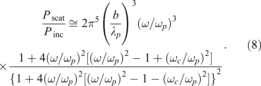
In order to obtain maximal scattering from the subwavelength gyrotropic cylinder, the operational frequency needs to correspond to a resonance of the object. In other words, we aim at maximizing the quantity , which, for small and after dropping the negligible term, takes the form
The scattering resonance of this cylinder occurs when the denominator of equation (8) vanishes (in reality, due to the presence of radiation loss, the scattered power never actually diverges, as extensively discussed, e.g. in the study by Monticone et al.28; quasi-static expressions, such as equation (8) typically neglects radiation loss). From equation (8), we obtain the quasi-static dipolar resonance condition
Contrary to equation (7), the condition (9) can be satisfied for any . Most importantly, it possesses two branches of solutions, associated with the individual resonances of the dipolar terms and , with a degenerate solution at and , corresponding to the conventional dipolar resonance of an unbiased isotropic cylinder. Also note that ωc, unlike ω, can be negative since the sign simply indicates the direction of the magnetic bias.
To confirm these quasi-static results, we report in Figure 2 the normalized scattered power of a gyrotropic cylinder (), on the plane, obtained by exact Mie-theory calculations. The solid black line corresponds to condition (7) for maximal scattering pattern rotation, and the dashed white lines to the resonant condition (9) for maximal scattering. The exact calculations are in good agreement with the quasi-static analytical predictions. In particular, we indeed observe a bifurcated pattern for the scattered power in this parameter space, associated with the effect of the static bias that lifts the degeneracy of the dipolar resonances of and . This can be considered as a scattering manifestation of the well-known Zeeman effect,12,13 which occurs when an external magnetic field results in the splitting of spectral lines. Indeed, a magnetic bias gives “rotational preference” to the system and makes the moving electrons behave differently depending on their sense of direction. Such a splitting is relatively well captured by the predictions of equation (9); the differences are attributed to the non-negligible size of the cylinder () and the presence of radiation loss, which is neglected by equation (9). The estimation given by equation (9) of the left resonant branch () is more accurate compared to the right resonant branch (), because the former corresponds to lower frequencies, hence the rod is electrically thinner. However, both branches overestimate the operational frequencies supporting the maximal scattering for a given . Furthermore, the decrease of as the cyclotron frequency is increased (which is also observed in Figure 1(b) and (c)), is clearly confirmed by the results of Figure 2.
Normalized scattered power , as a function of operating frequency and cyclotron frequency for an infinite cylinder with and (obtained by exact Mie-theory calculations). The solid black line corresponds to condition (7) for maximal rotation of dipolar radiation pattern, and the dashed white lines indicate the condition (9) for maximal resonant scattering. The four insets show the spatial distributions (time-snapshot) of the normalized scattered magnetic field for four characteristic designs indicated by different points on the contour plot.
To offer more physical insight, four characteristic designs, indicated by different points in Figure 2, have been numerically simulated (full-wave finite-element simulations using a commercial software COMSOL (5.3)).29 The spatial distributions of the scattered magnetic field (z-component) are shown in the corresponding insets, under TEz plane-wave incidence propagating toward the positive x-axis. For an unbiased cylinder (), we select the frequency giving maximum , and obtain the conventional dipolar resonance of a plasmonic cylinder, associated with the excitation of a localized surface-plasmon polariton.30,31 The resulting scattering pattern (bottom left inset) is that of a y-oriented induced dipole, as dictated by the incident electric field. The other three considered cases have the same bias, , but different frequency. The two resonant branches of the split surface-plasmon resonance correspond to circularly polarized induced dipoles with opposite sense of rotation, which yield a helical distribution of scattered field (two upper insets) with different angular momentum, similar to the response observed by Eskin et al.8 This unusual scattering response is attributed to the fact that one of the two coefficients becomes much larger than the other according to equation (5). Indeed, when practically only one of is present, the response is dominated by a circularly polarized dipole of certain helicity or, equivalently, two orthogonal linear dipoles oscillating out-of-phase (). Conversely, when both of the coefficients are non-negligible—but unequal—more complicated scattering field distributions are obtained. For example, by operating near the black line in Figure 2, corresponding to the condition for maximally rotated radiation pattern (7) (bottom right inset), we can clearly see the tilt in the induced dipole, which produces a skewed bipolar pattern; such a near-field distribution corresponds to far-field signatures of the type in Figure 1(c).
We also note that the monopolar term S0 may also diverge according to equation (4), yielding an additional scattering peak. In fact, by inspection of equation (4), we have . This resonance condition is analogous to the so-called volume-plasmon resonances for ε = 0,32 and it occurs in our case for . This resonance is absent for an unbiased cylinder where , whereas, in the presence of nonzero bias, a vanishing εt gives an unbounded εeff. However, this resonance has very high quality factor, hence it is completely damped in the presence of very small losses, as in the case considered in Figure 2 with .
Core–shell gyrotropic cylinder
Quasi-static analysis
The same mathematical formulation used above can be applied to the relevant case of core–shell gyrotropic cylinders. The scatterer is composed of a core cylinder of radius a and permittivity tensor with parameters (), as in equation (1), and cyclotron frequency , which is covered by a gyrotropic cladding of thickness () and respective parameters (). For simplicity, we assume a common plasma frequency ωp for both core and cladding materials and consider the two cases in which only one of the two bias fields () is nonzero, namely, either the cladding or the core is gyrotropic.
When only the internal cylinder is biased ( and ), the dominant scattering coefficients (dipolar terms, ) of an electrically small particle () take the form
Instead, when only the coating layer is magnetically biased ( and ), the corresponding quasi-static expressions can be written as
As in the previous section, the poles of equations (10), (11) give the scattering resonances of the core–shell particles. The analysis of the anomalous behavior of these resonances is the main goal of this study. As expected, when for equation (10) (isotropic shell vanishes) or for equation (11) (isotropic core vanishes), both equations become identical to equation (5) for a single gyrotropic cylinder, and the scatterer respects condition (9) for Zeeman-split localized surface–plasmon resonances.
The extra parameter a/b in the core–shell case not only provides more flexibility in controlling these plasmonic resonances, but it also leads to the emergence of additional resonances. Indeed, its presence makes the denominators of equations (10) and (11) a fourth-order polynomial with respect to , unlike the denominator of equation (8), which is a second-order polynomial. In the next section, we elucidate the properties of these scattering resonances of core–shell gyrotropic scatterers and discuss their relation with so-called Fano resonances and embedded eigenstates.
Gyrotropy-induced plasmonic resonances and Fano resonances
In Figure 3, we consider a cylindrical core–shell scatterer () with biased core, and plot the “regions of existence” of a scattering resonance in the parameter space defined by . The lighter regions (label: YES) correspond to frequencies at which a dipolar resonance can exist for a physical scatterer with (for which in equation (10) diverges), whereas the darker regions (label: NO) correspond to frequencies at which scattering resonances are not attainable for any physical value of a/b. We note that for very low bias (low ), scattering resonances occur at two discrete frequencies. These frequencies are: (i) , corresponding to a conventional surface-plasmon resonance (), and (ii) , corresponding to a vanishing volume-plasmon resonance (). As further discussed in the following, while the former resonance has a nonzero linewidth even in the unbiased case, the latter exhibits a diverging quality factor, and it corresponds to a non-radiating eigenmode, or embedded eigenstate, of the scatterer, an extreme scattering effect extensively studied in recent years.15–18
Regions of existence of a dipolar scattering resonance in the parameter space defined by for a core–shell cylinder with biased core. The light (dark) regions indicate that at least one physical value (none) of aspect ratio a/b exists that makes equation (10) singular (corresponding to a dipolar scattering resonance). For , the normalized scattered power is shown in the two bottom insets with respect to frequency and aspect ratio, obtained by quasi-static calculations (lighter colors indicate larger values). The outer radius is fixed, .
As we increase ωc, we see in Figure 3 that resonant scattering can be attained over a wider region of the parameter space for a suitably chosen aspect ratio a/b. We also note that if ωc increases beyond a certain value, resonant scattering is attainable over a very wide frequency range by properly choosing the size of the core.
Fixing ωc to a specific value (, indicated by a dashed line in Figure 3), we plot the normalized scattering power in the insets of Figure 3 across two different frequency bands, as a function of the aspect ratio a/b. In the lower left inset, we examine the range centered at . For , namely, when the entire particle is biased, we observe a substantial Zeeman split of the resonances, which is reduced when the core size is decreased. This result is expected since the bias is applied to a smaller portion of the cylinder and, therefore, the imposed rotational asymmetry diminishes. In the lower right inset, we consider the second resonance band, , centered at . Interestingly, the resonant branches in this range are very different compared to the conventional surface–plasmon resonances in the left inset. Both bright resonant bands are accompanied by a dark zero-scattering band nearby, producing an asymmetric resonant lineshape that reveals the Fano-resonant nature of these additional scattering features. Remarkably, as the geometry tends to the extreme cases, and , the scattering zeros and resonances perfectly merge, determining a resonance with diverging quality factor in the lossless limit, which corresponds again to a non-radiating eigenmode of the cylindrical scatterer. Of particular relevance is the region close to , where two asymmetric Fano resonances collapse into a doubly degenerate embedded eigenstate. This analysis therefore reveals new examples of extreme Fano resonances and embedded eigenstates, tunable by varying the applied bias.
In Figure 4, we consider the same cylindrical particle as in Figure 3 (), but with a biased shell and an unbiased core. For this case, equation (11) determines the resonances of the system. Similar considerations regarding the regions of existence for scattering resonances apply to this case. The logical contour is the same to that of Figure 3 with the difference that increasing bias does not always lead to more resonances at bands around a central frequency; in fact for , it seems that one cannot reach resonance for any ωc within the considered range. By observing the lower left inset of Figure 4, we note that Zeeman splitting increases now for decreasing a/b, which is expected because, if , the device is completely unbiased and a single degenerate plasmonic resonance is obtained. Remarkably, however, the second resonance (lower right inset) splits in the same way as in the biased-core case in 3, namely, the two branches get separated as a/b is decreased. This shows that what counts for the “shape” of the second resonance is mostly the interaction between the two different layers of various size, rather than the fact that either one or the other is biased.
Similar to Figure 3 but for a core–shell cylinder with biased shell. The poles of equation (11) determine the dipolar scattering resonances.
To further elucidate the behavior of this second pair of scattering resonances, we show in Figure 5 the scattering spectrum for a core–shell cylinder with and the same bias as in the insets of Figure 3, as a function of in a very narrow frequency range in the vicinity of . As mentioned above, for a large aspect ratio (almost the entire cylinder is biased with a thin unbiased shell around it), the object exhibits an extreme scattering signature: two ultrasharp asymmetric Fano resonances on the verge of merging into a doubly degenerate embedded eigenstates. As a result, we observe two resonant peaks at very close wavelengths, each one of them accompanied by a scattering dip at slightly lower frequencies. By changing ω by a fraction (0.2%) of the common plasma frequency, the scattering response varies dramatically as seen in the bottom insets of Figure 5, which shows the spatial distribution of . At the minimum of this curve, extremely weak dipolar scattering is obtained; conversely, at the maximum, the scattered power is orders of magnitude larger, and the scattered field is associated with a circularly polarized induced dipole, as in the upper insets of Figure 2 (opposite handedness is obtained at the other peak of Figure 5). Such a substantial change in the behavior of a small scatterer in a very narrow frequency range—from high scattering, to zero scattering, to high scattering again but with opposite angular momentum—may be employed in highly selective (chiral) sensors and switching applications.
Scattered power normalized by the incident power as a function of the operational frequency in a very narrow region around the plasma frequency (obtained by exact Mie-theory calculations). Spatial distributions (time-snapshots) of are shown in the insets for two extreme cases: invisible scatterer (left) and resonant scatterer (right), at two neighboring frequencies, with the same colorscale. Plot parameters: , .
Conclusion
In summary, we have studied the scattering properties of homogeneous and core–shell gyrotropic cylinders, an important class of complex scatterers of large relevance in the context of novel nonreciprocal and topological metamaterials. We have showed that the presence of an external bias splits the dipolar scattering resonances into distinct resonances for circularly polarized dipoles of opposite helicity, an effect analogous to the Zeeman splitting of atomic spectral lines. We have also discussed the possibility of using the external bias to rotate the orientation of the dipolar scattering pattern of the gyrotropic cylinder, until it becomes almost orthogonal to the incident electric field. This effect may be useful to tune and direct the scattered field in desired directions. Finally, we have also studied the presence of multiple ultrasharp Fano resonances in the spectrum of core–shell gyrotropic cylinders, which can also be merged into doubly degenerate embedded eigenstates. These sharp scattering signatures may find applications in tunable scattering switches and sensors.
We believe that all these intriguing effects may enable a new degree of freedom in the design of anomalous and extreme scatterers, with large potential implications in different practical scenarios.
Footnotes
Declaration of conflicting interests
The author(s) declared no potential conflicts of interest with respect to the research, authorship, and/or publication of this article.
Funding
The author(s) disclosed receipt of the following financial support for the research, authorship, and/or publication of this article: This work was supported by the Nazarbayev University Small grant no. 090118FD5349; Nazarbayev University ORAU grant no. 20162031; MES RK state-targeted program BR0523 6454 to CV; and National Science Foundation (NSF) with grant no. 1741694 to SAHG and FM.
ORCID iD
Francesco Monticone
References
1.
WangZChongYJoannopoulosJD. Observation of unidirectional backscattering-immune topological electromagnetic states. Nature2009; 461: 772–775.
GangarajSAHMonticoneF. Topological wave-guiding near an exceptional point: defect-immune, slow-light, loss-immune propagation. Phys Rev Lett2018; 121: 093901.
5.
GangarajSAHNemilentsauAHansonGW. The effects of three-dimensional defects on one-way surface plasmon propagation for photonic topological insulators comprised of continuum media. Sci Rep2016; 6: 30055.
6.
GangarajSAHSilveirinhaMGHansonGW. Berry phase, berry connection, and chern number for a continuum bianisotropic material from a classical electromagnetics perspective. IEEE J Multiscale Multiphys Comput Techn2017; 2: 3–17.
7.
Kort-KampWJMRosaFSSPinheiroFA. Molding the flow of light with a magnetic field: plasmonic cloaking and directional scattering. J Opt Soc Am A2014; 31: 1969–1976.
8.
EskinVAIvoninskyAVKudrinAV. Poynting vector behaviour during the resonance scattering of a plane electromagnetic wave by a gyrotropic cylinder. Phys Scr2015; 91(1): 015502.
9.
KoderaTSounasDLCalozC. Artificial Faraday rotation using a ring metamaterial structure without static magnetic field. Appl Phys Lett2011; 99: 31114.
10.
SounasDLCalozCAlùA. Giant non-reciprocity at the subwavelength scale using angular momentum-biased metamaterials. Nat Commun2013; 4: 2407.
AronovAGHikamiSLarkinAI. Zeeman effect on magnetoresistance in high-temperature superconductors. Phys Rev Lett1989; 62: 965–968.
13.
LeeEJHJiangXHouzetM. Spin-resolved andreev levels and parity crossings in hybrid superconductor–semiconductor nanostructures. Nature Nano2014; 9: 79–84.
14.
Luk’yanchukBZheludevNIMaierSA. The Fano resonance in plasmonic nanostructures and metamaterials. Nat Mater2010; 9: 707–715.
15.
SilveirinhaMG. Trapping light in open plasmonic nanostructures. Phys Rev A2014; 89: 23813.
16.
MonticoneFAlùA. Embedded photonic eigenvalues in 3D nanostructures. Phys Rev Lett2014; 112: 213903.
17.
HsuCWZhenBStoneAD. Bound states in the continuum. Nat Rev Mater2016; 1: 16048.
18.
MonticoneFDoelemanHMDen HollanderW. Trapping light in plain sight: embedded photonic eigenstates in zero-index metamaterials. Laser Photon Rev2018; 12: 1700220.
19.
BittencourtJA. Fundamentals of Plasma Physics. Berlin: Springer, 2010, pp. 375–386.
20.
FangKYuZLiuV. Ultracompact nonreciprocal optical isolator based on guided resonance in a magneto-optical photonic crystal slab. Opt Lett2011; 36(21): 4254–4256.
21.
ValagiannopoulosCA. Study of an electrically anisotropic cylinder excited magnetically by a straight strip line. Prog Electromagn Res2007; 73: 297–325.
22.
TretyakovSAViitanenAJMaslovskiSI. Impedance boundary conditions for regular dense arrays of dipole scatterers. IEEE Trans Antennas Propag2003; 51: 2073–2078.
23.
AmendolaVBakrOMStellacciF. A study of the surface plasmon resonance of silver nanoparticles by the discrete dipole approximation method: effect of shape, size, structure, and assembly. Plasmonics2010; 5: 85–97.
24.
AbramowitzMStegunIA. Handbook of Mathematical Functions. Gaithersburg: National Institute of Standards and Technology, 1964, pp. 358–364.
25.
NovotnyLHechtB.Principles of Nano-Optics. Cambridge: Cambridge University Press, 2006.
BohrenCFHuffmanDR. Absorption and Scattering of Light by Small Particles. Hoboken: John Wiley & Sons, 2008.
28.
MonticoneFAlùA. Scattering at the extreme with metamaterials and plasmonics. In: MaierS (ed.), World scientific handbook of metamaterials and plasmonics. Vol. 1. Singapore: World Scientific, 2017, pp. 295–335.
29.
COMSOL Multiphysics ver. 5.3, COMSOL AB, Stockholm, Sweden, http://www.comsol.com (accessed 23 June 2018).
30.
LukyanchukBSTernovskyV. Light scattering by a thin wire with a surface-plasmon resonance: Bifurcations of the Poynting vector field. Phys Rev B2006; 73: 235432.