
Abstract
The history of ocean renewable energy developments in Australia is reviewed. A layperson’s description of the physical operating principle is given for the main classes of technology that have been tested in Australian waters. The Australian marine domain possesses among the world’s most energetic wave-energy resources, driven by powerful mid-latitude westerly winds. The northern coast of Western Australia has tidal ranges significant on a global scale, and some geographical features around the continent have local tidal resonances. The East Australian Current, one of the world’s major western boundary currents, runs along the eastern Australian seaboard, offering potential for ocean-current energy. Sea-water temperatures in the tropical north-east of Australia may permit ocean thermal energy conversion. While this abundance of resources makes Australia an ideal location for technology development, the population is highly concentrated in a few large cities, and transmission infrastructure has developed over a century to supply cities from traditional power plants. Several wave-power developments have resulted in demonstration of deployments in Australian waters, three of which have been grid connected. Trials of tidal devices have also occurred, while other classes of ocean renewable energy have not yet been trialled. The prospects for marine renewable energy in Australia are discussed including non-traditional applications such as coastal protection and energy export.
Introduction
Over the past 10 years, Australia has been the setting for an increasing number of marine renewable energy developments, with several new developments reaching ocean trials in the last 5 years. Concepts for extracting power from the seas are not new, with energy having been extracted from tidal mills since at least the 6th century (Murphy, 2006), the first wave-power patent filed in France in 1799 (Falcão, 2010) and the first trial occurring in Australia in 1909 (Hemer and Griffith, 2011). However, the 21st century has seen significant government investment added to what has hitherto been largely private venture capital–funded developments. Most notably, the establishment of the Australian Renewable Energy Agency (ARENA) by the Australian Federal Government in 2012, plus significant support from some of the State Governments, has accelerated development as well as research. In a major review and analysis, the status and economic potential of Australian marine renewable energy was reviewed by Behrens et al. (2012a); they covered preliminary-level assessments of the available resource, including wave energy, tidal energy, ocean-current energy and ocean-thermal energy conversion (OTEC). Major examples of technologies developed overseas were reviewed, and an up-to-date survey of all marine renewable energy developments in Australia at the time was presented. Environmental and multiple-use issues associated with Australia’s marine domain were also canvassed. In a study specific to wave power, Behrens et al. (2012b) also combined an assessment of the wave resource with models of generic classes of ocean wave-energy converters (WECs) to predict the levelised cost of electricity around Australia. Hemer et al. (2016) updated the wave resource assessment.
The fundamental differences between wave energy, tidal energy, ocean-current energy and OTEC are detailed in a companion article (Manasseh et al., 2017). Wave energy is fundamentally a concentrated and averaged form of wind energy, generated by winds blowing over the World’s ocean basins, and hence, wave energy is large in oceans subjected to strong, steady winds. Winds are created by differences in the sun’s heat between the tropics and poles. Ocean-current energy is also due to the action of the winds, modified by the earth’s rotation. Meanwhile, ocean-thermal energy is more directly due to solar heating of the sea surface. All the above-mentioned forms of ocean renewable energy thus derive ultimately from the sun’s heat. In contrast, tidal energy is due to the gravity of celestial bodies, mostly the moon, and varies geographically due to the size and shape of continents, bays and inlets.
Compared with better-known forms of renewable energy such as wind and solar power, marine renewable energy demonstrates great diversity, complexity and, once installed in the water, the operating principles are largely invisible to the layperson. There has been no clear, detailed description of the operating principles of the marine renewable energy technologies used in Australia (and indeed no such description anywhere, to the best of our knowledge) that would be comprehensible to a lay readership. For example, it is not unusual to hear laypersons confusing wave and tidal power, despite their operating principles being vastly different and their geographic and economic opportunities being complementary rather than competitive. Thus, there is a need to review Australian developments in the context of the resource they tap and the specific principle they exploit.
The aim of this review is to describe in detail developments since the last review in 2012. We aim at a lay readership and include explanations of the operating principles such that the success, failure or potential of each development can be judged from an informed perspective. However, we do not review all proposed or trialled technologies, focusing on a selection that is representative of the major classes of device that have been trialled in the ocean. We also speculate on the prospects for the technologies and on the true advantages Australia may offer in this area of renewable energy. Examples of levelised costs of electricity for some resources are given in Table 5 (section ‘Engineering and economic efficiencies’) of a companion article (Manasseh et al., 2017), which focuses on the integration of marine renewable energy with the needs of coastal communities and includes a detailed system for decision-making on appropriate technologies.
The remainder of this article is structured as follows: In section ‘Geographical and climatic factors’, we discuss the geographic and climatic factors that determine the marine renewable energy resource in Australia. The resources and technologies related to wave energy, along with an historical account of device deployments in Australia, are reviewed in section ‘Australian wave energy’, while those related to tidal energy are discussed in section ‘Australian tidal energy’. Ocean-current power and OTEC are discussed briefly in section ‘Other marine renewables’, while a concluding discussion is presented in section ‘Discussion and conclusion’.
Geographical and climatic factors
Australia’s 34,000 km of coastline extends from a tropical climate in the north through a subtropical to a mid-latitude climate in the south (McInnes et al., 2016). Thus, the coastline north of approximately 20°S (Figure 1) experiences a wet monsoon season with winds mainly from the north-west from about October to March and a dry season where south-east trade winds prevail from about April to September. The seasons in the south of the continent are influenced by the movement of the subtropical ridge, a zone of atmospheric high pressure which delineates the trade easterly winds to its north and the mid-latitude westerlies to its south. The subtropical ridge reaches its maximum northward extent at around 30°S during the summer months (December to February) and around 40°S during the winter months (June to August) (McInnes et al., 2016). South of the subtropical ridge, mid-latitude low-pressure systems and their associated fronts bring powerful westerly to south-westerly winds and associated wave climate to the region.
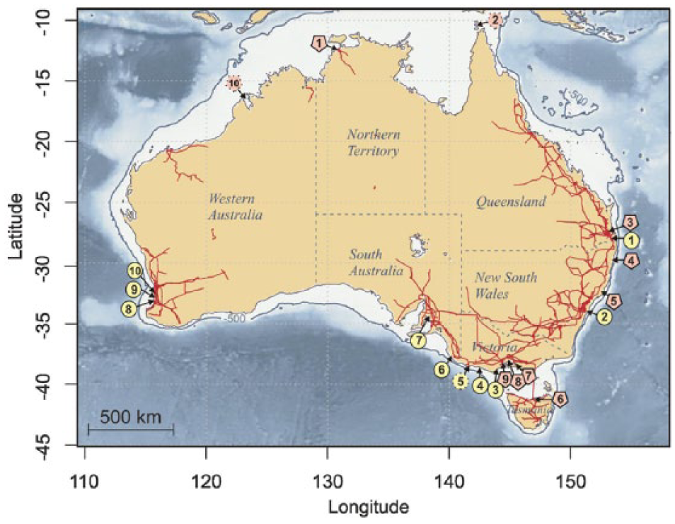
Map of Australia showing the electricity transmission lines and offshore bathymetry with the continental shelf indicated by the 500 m isobath. Locations of marine-energy trials in Australia are also indicated. Solid surrounded circles represent wave-energy trials, and pentagons represent tidal-energy trials, while symbols with dotted surrounds indicate locations where pre-trial feasibility assessments have been undertaken. Further details are provided in Table 1.
Due to Australia’s arid interior, approximately 80% of the population of 23 million people live at or near the coast. The majority (approximately 80%) of the total population live along the eastern and south-eastern seaboard from Queensland to South Australia including Tasmania (Figure 1). This is reflected in the connectivity of Australia’s electricity grid in the east of the continent as compared to the west (Figure 1).
Australia’s vast coastline gives rise to a large potential marine-energy resource. In particular, its extensive Southern Ocean exposure means it has one of the richest wave-energy resources of any country (Lewis et al., 2011). The nature of the marine-energy resource in a given location is influenced by attributes such as continental shelf width, bathymetric depth and coastline orientation in relation to prevailing weather conditions. For example, large tidal amplitudes coincide with relatively wide and shallow continental shelf regions where bottom friction amplifies the maximum water levels. The north-west shelf of Australia has the largest tidal range in the country with a maximum tidal range at King Sound (Figure 1 and Table 1) of up to 11.8 m. A large tidal range of around 5 m also occurs on the Queensland coast between 20 and 24°S (Behrens et al., 2012a). Conversely, the wave-energy resource near to shore on the north-west shelf and Northern Territory is limited (Hemer et al., 2016). This is in part due to coral reefs, found along these coastlines, which enhance wave dissipation offshore (McInnes et al., 2016).
Attributes of wave- and tidal-energy devices considered or sea trialled around Australia.
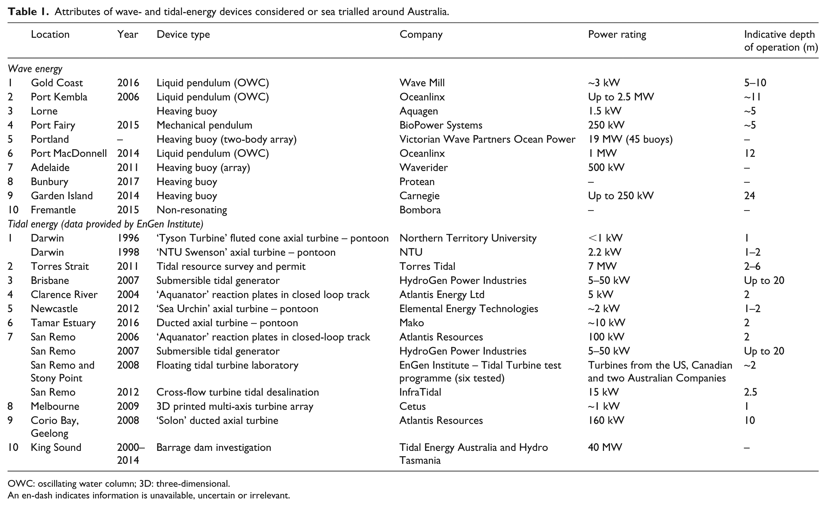
OWC: oscillating water column; 3D: three-dimensional.
An en-dash indicates information is unavailable, uncertain or irrelevant.
Australia’s east coast also features a major southward flowing boundary current – The East Australian Current (EAC) – which is the western extent of the South Pacific tropical gyre circulation. A comprehensive assessment of the resource potential of the EAC has not been undertaken (Behrens et al., 2012a); however, Griffin and Hemer (2010) indicate that this resource (of order tens of terawatt-hours/year) is probably much less than Australia’s electricity needs. Ocean thermal and salinity gradients also offer a potential marine-energy resource in Australian waters. Although detailed assessments of this resource have not been made yet, Behrens et al. (2012a) identified that the most promising Australian OTEC sites are located at distances of >100 km off the North Queensland coast.
Australian wave energy
Resources
Based on a comprehensive assessment of wave-energy resource in Australia, Hemer et al. (2016) estimate the total wave-energy flux across the depths of 25, 50 and 200 m to be 1796, 2652 and 2730 TW h/year, respectively. This available energy is an order of magnitude larger than the 248 TW h electricity generated in Australia in 2013–2014 (Department of Industry and Science, 2015), confirming the magnitude of the wave resource is not a constraint to its future uptake. The vast majority of this resource is available to the southern coastal region with 1455 TW h/year estimated at the 25 m-deep contour from 29°S on the Western Australian coast to 148°E on the southern tip of Tasmania including western Victoria. By contrast, the wave-energy resource over northern Western Australia (north of 23.5°S) and Northern Territory at the 25 m contour is only 61 TW h/year.
Wave variability is also an important consideration for wave-energy extraction. At the 25 m isobath (the depth around which many wave devices are presently being tested), much of the southern, mid-latitude coastal region is also favourable because it displays relatively low variability in wave energy with respect to the total available wave energy. Large waves are generally not much greater than the wave height at which most energy is received, and episodes of minimum wave heights and energy (significant wave height, Hs, of <1 m) are relatively short-lived (durations typically <1 day) and relatively uncommon (typically >100 days between events). Conversely, in the tropical north, the lower available wave resource is also characterised by a larger ratio of large waves to mean wave height due to the occurrence of tropical cyclones. This region also experiences periods of minimal wave energy that are more frequent and of longer duration (Hemer et al., 2016).
Reasons for the diversity of WEC designs
Fundamental factors of physics and engineering have led to the development of a great diversity of WEC designs worldwide. Significant research and development began in the 1970s (Salter, 1974) and accelerated in the late 20th century (Falcão, 2010). In the present day, there are over 250 wave-energy companies (The European Marine Energy Centre, 2016), mostly with technologically distinct devices. On first glance, many of these devices appear totally different. The facile conclusion would be that the ideal technology has not yet emerged, and that investors and governments should wait for clarity before serious investment. However, this conclusion would be incorrect since, as explained in Manasseh et al. (2017), there is much greater similarity than first appears. Most, though not all, WECs are designed to have a natural frequency with which they will oscillate if disturbed from a state of rest. This natural frequency is designed by the engineer to match the frequency of the prevailing ocean waves; when the frequencies match, resonance occurs, corresponding to a large motion of the machine relative to the water and consequently a large extraction of power from ocean waves (Manasseh et al., 2017). The enormous advantage of resonance is that the WEC is able to remove power from waves over an area of ocean larger than the machine’s physical size. The maximum theoretical length of wave crest that a resonating point-absorber WEC can absorb,
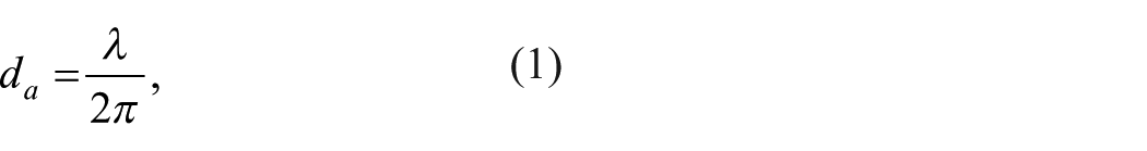
where λ is the wavelength of the ocean waves (the length from crest to crest). However, there are very many types of mechanisms that have a natural frequency. Indeed, all the Australian WECs that have been ocean-tested, apart from one (see section ‘Non-resonating developments’), are resonators. The reason for the diversity in WEC designs is the unfortunate – and interesting – combination of two very simple issues, as detailed below.
First, the simplest way to generate electricity is by mechanically rotating a shaft in one direction only. Once there is a rotating shaft, via gears and an electrical machine, electricity can be generated, transmitted and sold. However, the physics of wave action dictates that the motive fluid, water, is inherently reciprocating: The water reverses its motion every cycle, going in one direction on the wave crest and the opposite direction on the trough. Thus, the momentum available for conversion into torque and useful power is constantly changing from positive to negative, no matter which direction one chooses. Contrast this with the water exiting a dam, which flows solely down-hill, or with the wind, which is air flowing solely from atmospheric high- to low-pressure systems; in these cases, the motive fluid flows in one direction.
If the motive fluid, be it air or water, is moving in one direction, or even mostly in one direction, the technology necessary to extract useful power from this unidirectional flow is simple. All that is required is a single moving part, the turbine. A turbine is a rotating shaft with fixed blades attached to it. Whether in the form of a medieval water wheel or modern hydroelectric turbine, an ancient windmill or modern wind turbine, the concept is the same: a rotating shaft, with blades fixed to it. However, for reciprocating motion such as that due to waves, an efficient transformation to rotating-shaft motion is not possible with a single moving part. For example, the efficient reciprocating-to-rotary transformation inside the classical internal combustion engine requires three parts: the piston, the crank and the crankshaft, connected by two joints and a sliding interface. Meanwhile, the cup anemometer is an example of single-moving-part mechanism that turns in one direction irrespective of the direction of airflow; it is fine for measuring the speed of wind flow but very inefficient if one tried to extract useful power from it.
The second issue is that machines in the ocean must be engineered to minimise the number of moving joints in the water. The tripartite mechanism of the internal combustion engine functions perfectly in a sealed, lubricated housing. In the ocean, however, biofouling, sediments and salt water make joints problematic. Moreover, for reasons explained in section ‘Pitching developments’, the machines must be very large, implying very large forces are applied to large joints subjected to biofouling, sediment ingress and saline attack.
While some WECs have been designed to generate electricity directly from a reversing linear motion, this entails its own issues of electrical engineering. Thus, the majority of WEC designs achieve some form of reciprocating-to-rotary transformation. There are very many ways of doing this, and due to the concomitant need to minimise underwater joints and sliders, none of the designs is perfect. Consequently, WEC design is an appealing challenge for inventors. Moreover, mechanical devices can be conceived without a formal engineering education, and thus, more WECs are being invented every year. Some can be shown by a back-of-the-envelope calculation to be unrealistic, but many others are genuinely innovative concepts not readily disproven.
Furthermore, the ease with which new inventions can be created means that many new patents can be filed. This, in turn, makes many small start-up companies possible, each based on unique intellectual property (IP). Despite the relative ease of filing IP, the ability of a company to demonstrate its idea is dependent on being able to attract significant amounts of capital.
This diversity means that even the task of classifying WECs is not simple. Classifications are discussed in detail in a companion article (Manasseh et al., 2017). For the purposes of this article, it is sufficient to note that Australian WEC designs have covered many WEC types, possibly due to the ease of patenting inherent to WEC concepts rather to an intent to match the WEC type to the application. The operating-principle classification proposed in Manasseh et al. (2017) is adopted.
Technologies
Liquid-pendulum (oscillating water column) developments
The oscillating water column (OWC) was the first concept for extracting power from ocean waves to be implemented in practice and has led to the longest-surviving installations (Falcão, 2010; Heath, 2012). It is also the first WEC concept to be implemented in Australia. The survivability of the OWC can be understood once its operating principle is appreciated. In its most elementary form, it is simply a tube open at both ends, with its top in the air and immersed in water by a length L. It is easy to show that its natural frequency f0 (s−1) is given by
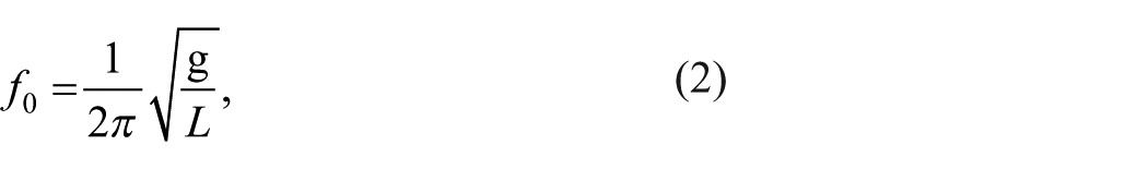
where g is the acceleration due to gravity (Figure 2(a)). This is the equation of a pendulum of length L; hence, it is a natural oscillator. Indeed, it is possible to observe one or two natural oscillation cycles using a large drinking straw dipped at depth L into a glass of water, sucking up a column of water and then letting the water fall back into the glass. Like any natural oscillator, it will resonate when driven by frequencies close to f0. Thus, L is ‘tuned’ during the machine’s design to match the prevailing frequency of ocean waves where the machine is to operate (Manasseh et al., 2017). There are no moving parts in the water, a major contributor to the simplicity and survivability of the OWC concept. However, the need to transform oscillatory motion into rotary motion, as noted in section ‘Reasons for the diversity of WEC designs’, is nonetheless still an issue. To generate electricity, most OWC designs use a bi-directional turbine mounted the air above the water column. The turbine rotates in the same direction irrespective of the direction of airflow alternately pushed and pulled by the water surface. The bi-directional turbine may be of a type with fixed blades, which is inevitably less effective than conventional unidirectional turbines. Alternatively, it may be a turbine whose blades can be rotated to vary their pitch, which introduces very many moving parts, albeit only in the air (Falcão, 2010).
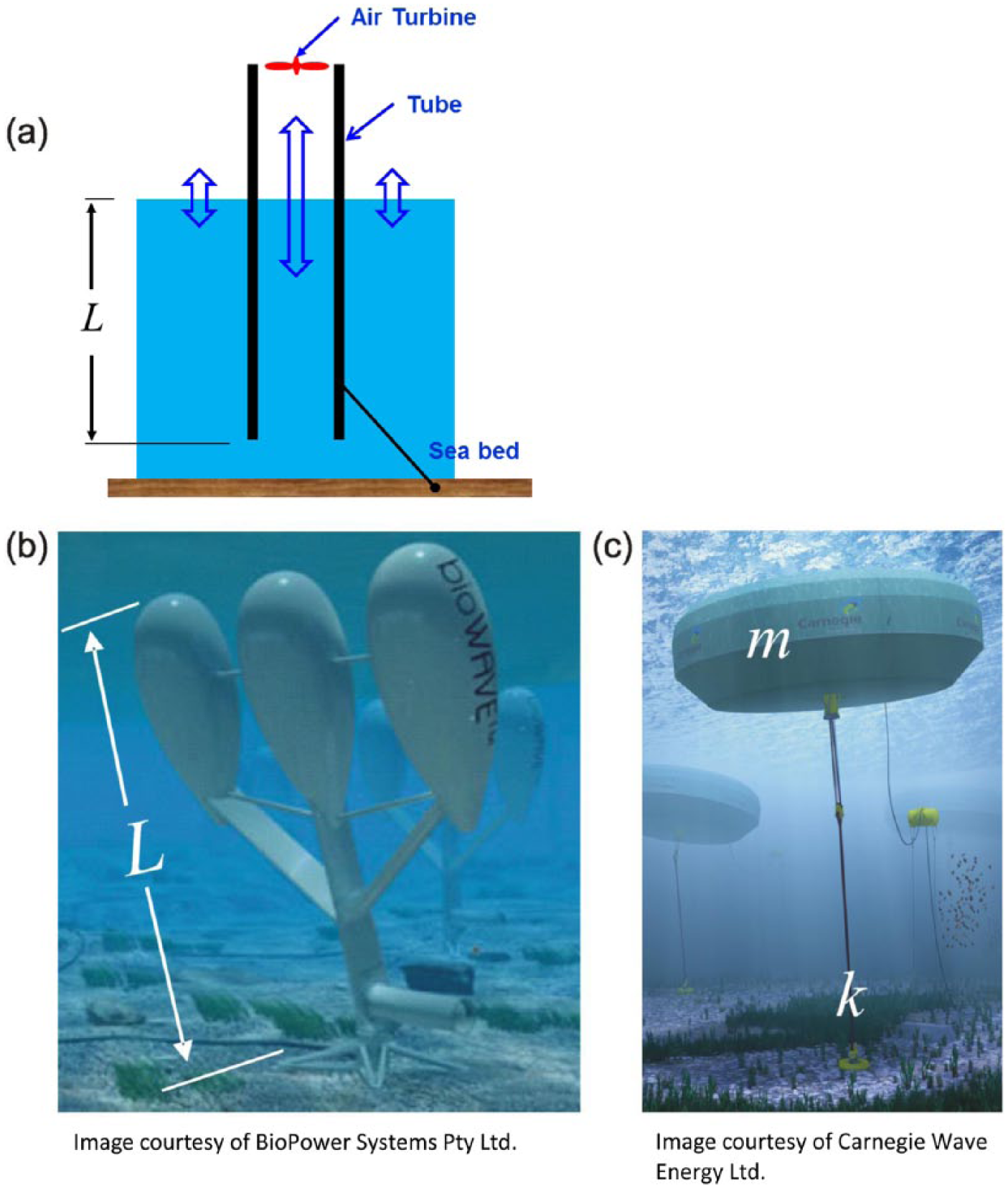
Illustration of the operating principles for (a) liquid pendulum, (b) mechanical pendulum and (c) heaving-buoy devices. In (a) and (b), the natural oscillating frequency is given by equation (2), and in (c), the natural oscillating frequency is given by equation (3).
A ‘back-of-the-envelope’ calculation using equation (2) immediately explains the issue mentioned in section ‘Reasons for the diversity of WEC designs’: The machines must be very large. Ocean swell, which contains the highest energy, has a low frequency. On the coasts of Australia exposed to Southern Ocean swell, this frequency is typically below
A further advantage of the OWC, partially mitigating the need for installation in great depth, is that its theoretical natural frequency given by equation (2) is maintained irrespective of the geometry of the underwater part of the ‘tube’. As long as there is a total length L of enclosed duct, chamber or pipe, this length can theoretically be any shape at all, not simply a tube pointing straight down. Indeed, many OWC designs have a ‘bent duct’, such that the length L is literally L-shaped, with the base of the ‘L’ horizontal and thus water flowing horizontally into and out of the underwater opening. This means the device can be situated in water that is shallower than L, opening up a wider range of sites. The larger the diameter (width) of the duct, the greater the power that may be extracted; power in the order of 1 MW requires a width approaching 10 m or more.
Furthermore, the pressure exerted by passing waves can vary with depth, which has consequences for the design of all WECs. Classical theory due to Airy in 1841 (e.g. Gill, 1982) shows that in ‘deep’ water, defined as deeper than about 1/2 of the wavelength, the pressure and velocity decrease exponentially with depth. The wavelength can be over 100 m on the Southern Ocean and southern Indian Ocean coasts of Australia (Behrens et al., 2012b). In ‘shallow’ water, defined as water shallower than 1/20 of the wavelength, the pressure and velocity (the ‘wave action’) are invariant with depth. Water depths between 1/2 and 1/20 of the wavelength are called intermediate, and the wave motion decreases with depth, though not as rapidly as in deep water. Thus, in all but shallow-water regimes, having a bent duct enables the entrance to the duct to be closer to the surface and to be subjected to a greater forcing, permitting greater energy extraction from waves. Nonetheless, to benefit from the maximum in wave motion at the surface, the required water column length would have to be shaped into a ‘U’, not a ‘L’, and indeed, U-shaped OWCs have been constructed overseas (Arena et al., 2013). It is also worth noting that at every bend in the water column, energy is lost to vortices formed at the bends (Fleming et al., 2012) and thus is unavailable for electricity generation.
The first OWCs were installed in the 19th century off the US East coast, not to generate electricity but to power navigation-warning whistles, and there were 34 such OWCs operating by 1885 (Heath, 2012). Electricity-generating OWCs were developed in 1910, when Mr Bochaix-Praceique supplied his house with 1 kW of electricity using an OWC concept (Palme, 1920). Several further examples were installed in Japan, Europe and India over the 20th century (Falcão, 2010; Heath, 2012). A 150 kW OWC was installed at Vizhinjam, Kerala, India, in 1990 (Manasseh et al., 2017; Sundar et al., 2010); it was grid connected and operated for about 20 years while subjected to several improvements. The grid-connected 500 kW LIMPET OWC at Islay, Scotland, United Kingdom, commenced operations in 2000, following a grid-connected trial of a smaller machine that lasted 9 years (Heath, 2012). The LIMPET plant was closed in 2013 following a strategic-direction change by the operating company (US Department of Energy, 2016). Significantly, the long-lived installations in India and the United Kingdom were shore mounted and thus unsinkable and easily accessible for maintenance.
The first Australian OWC developments were made by the company Energetech, founded in 1997 in Sydney by Tom Denniss; it changed its name to Oceanlinx (2016) in 2007. It was initially funded by venture capital and eventually by Australian government grants. The company’s first installation, denoted MK1, was a bent-duct OWC that sat on the seabed in shallow water at Port Kembla, New South Wales. It should be noted that on the eastern coast of Australia, unlike the southern coast, peak wave frequencies are generally higher, between 0.1 and
A larger, grid-connected, machine, the MK3, was installed at Port Kembla in March 2010. Similar to some of the earliest OWC designs, the MK3 was designed to float and was moored to the seabed. It was designed to house a number of OWCs on a common platform, giving a total generation capacity of 2.5 MW and operated successfully (Oceanlinx, 2016). However, it was wrecked in May 2010 when it broke its moorings in rough seas (Hasham, 2010). The Port Kembla machines were of steel construction.
Oceanlinx received funding from ARENA (2014), permitting design and construction of a further prototype, ‘GreenWave’. By this stage, the company’s key IP appeared to be the design of its bi-directional turbine (Carley and Denniss, 2000), although the internal structure of the ducting had also been subjected to significant research (Fleming et al., 2012). This machine’s structure was made of concrete and intended to sit on the seabed. A single turbine was rated at 1 MW. It was constructed in Port Adelaide, South Australia (Figure 3), where there is a submersible construction facility capable of handling the 3000 t structure. The intended location was Port MacDonnell, South Australia, approximately 450 km south-east of Adelaide.
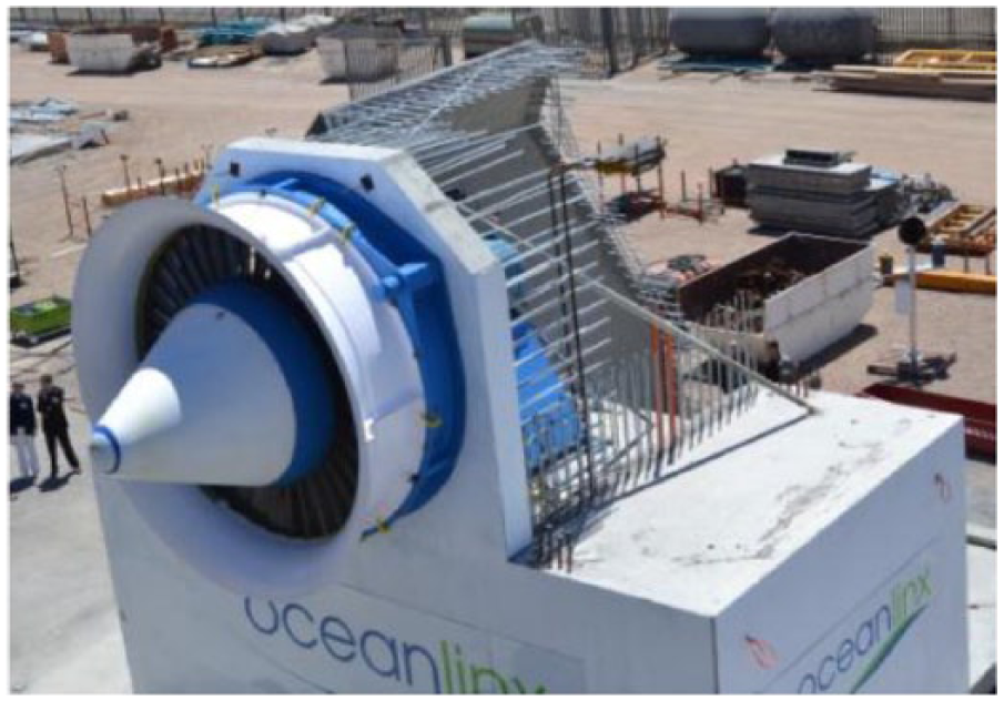
The Oceanlinx 1 MW bottom-mounted bent-duct OWC, showing the turbine, under construction in Port Adelaide, South Australia, in October 2013.
In March 2014, the concrete machine was successfully rendered buoyant with air bags and towing to Port MacDonnell commenced. However, rough seas damaged the air bags during the tow (Australian Broadcasting Corporation, 2014), and it was damaged beyond repair (England, 2014). Thus, the firm was unable to meet contractual obligations imposed by investors and went into liquidation (England, 2014). However, the IP was transferred to a new corporate structure, and the company has emerged as a Hong Kong-based concern with plans to deploy OWC technology in Taiwan (Oceanlinx, 2016).
These Australian developments remain the most ambitious developments of the OWC concept to date. They went beyond the secure, shore-based OWCs or the temporary trials of floating OWCs undertaken previously. Machines were deployed that were the outcome of a long series of incremental trials and re-developments.
In general, due to the lack of moving parts in the water and thus easy integration into a wall, OWCs that are bottom mounted are well suited to protection of the coast from waves, an application that has been implemented in Europe (e.g. Arena et al., 2013; Torre-Enciso et al., 2010) but has not yet been planned in Australia. Coastal protection is discussed in section ‘Discussion and conclusion’ and in Manasseh et al. (2017).
A new OWC concept, the ‘Wave Mill’, was tested at the Gold Coast, Queensland (Voropaev, 2016). This concept (Figure 4) realises an ingenious idea to avoid the need for a bi-directional turbine. A row of OWCs is arranged at right angles to the incoming wave crests. The row is at least as long as a wavelength of the incoming swell. When air is pushed out of each OWC, it passes through a one-way valve which is a simple flexible plate hinged at the top, rather like a ‘cat flap’; the air exhausts into a common exhaust plenum chamber running parallel to the row. Air is sucked in from a one-way valve on the opposite side of each OWC, coming from a common inlet plenum chamber. Because the row of OWCs is longer than a wavelength, one OWC is always maximally exhausting air and another is maximally intaking air at any given time. The exhaust and inlet chambers communicate via a turbine that thus turns in one direction only. Moreover, the turbine turns at a steady speed as long as the incoming swell is steady and not changing in amplitude along the row. In contrast, the bi-directional turbines of other OWC concepts are constantly speeding up and slowing down, with maximum speeds on the crest and trough. While one-way valves are used to rectify oscillatory flow to unidirectional flow in a few other OWC designs (Heath, 2012), the Wave Mill appears to be the only concept that could achieve a constant turbine speed, at least for incoming waves that do not vary from wave to wave. One possible drawback is the power lost as the air passes through the valve; as noted below, this issue inevitably affects several technologies that have been deployed.
The Wave Mill set of OWCs, under trial at the Gold Coast, Queensland.
Mechanical-pendulum developments
While the OWC’s operating principle can be simplified to that of a liquid pendulum, a rigid mechanical pendulum inherently operates with a natural frequency given by the pendulum equation (2), as illustrated in Figure 2(b). Several concepts have been developed and installed around the world (e.g. Henry et al., 2014), taking the form of underwater flaps or cylinders hinged at the bottom. The advantage of a bottom-hinged pendulum is that its maximum motion is close to the surface, where (as noted in section ‘Reasons for the diversity of WEC designs’) the velocity and pressure induced by waves are also maximum, permitting efficient transfer of energy to the motion of the machine. This offers an advantage over the bent-duct OWC, which has an entrance below the surface. Since the length of the pendulum is determined by equation (2), and, unlike the OWC, the length L must be straight, a mechanical-pendulum WEC must be deployed in water no shallower than L. Furthermore, as just noted, the maximum in wave action is at the surface; to take advantage of this, the water in which it is deployed should not be much deeper than L. Therefore, there are more constraints on the siting of mechanical pendulums.
A machine called ‘BioWAVE’ (Finnigan and Caska, 2006) was developed by BioPower Systems (BPS, 2016a), a company founded by Tim Finnigan in Sydney in 2006 (Figure 5(a)). While this machine is described in this section as a mechanical pendulum, it has elements of the heaving buoy described in section ‘Heaving-buoy developments’. The machine consists of three cylindrical chambers, arranged rather like the tines of a fork, which branch from a stem hinged at the bottom. The design in the form of parallel cylinders with gaps between them, rather than the continuous solid flaps of similar mechanical pendulum trialled elsewhere, was thought to create beneficial interactions between the cylinders. Each cylinder was thought to act as an individual device in an array (Caska and Finnigan, 2007); it is known that array interactions of devices can increase device output due to surface-wave radiative coupling (Budal, 1977; De Chowdhury et al., 2015). Although it is not stated by the authors representing BPS, it is also possible that the design may allow it to benefit from an additional resonance due to vortex-induced vibration (VIV; Gabbai and Benaroya, 2005).
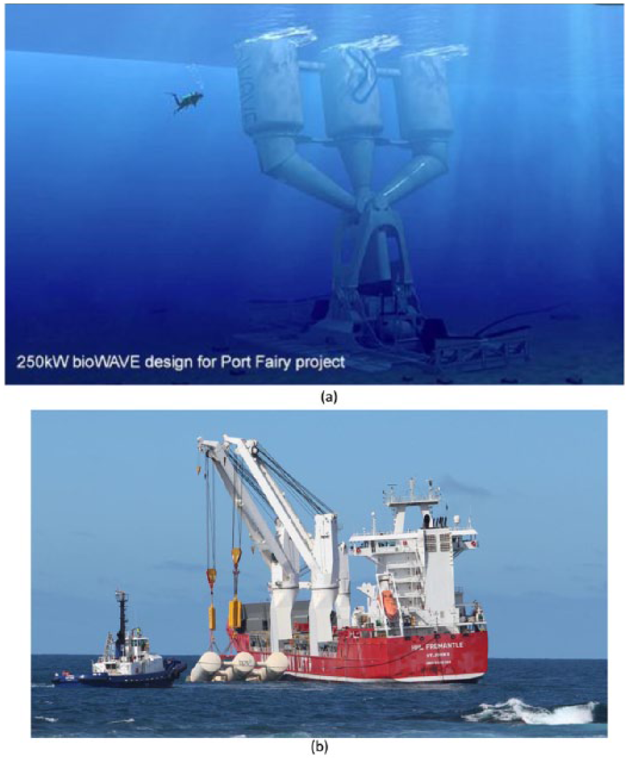
The BioPower Systems 250 kW machine, installed at Port Fairy, Victoria, in December 2015: (a) artist’s impression of installation and (b) deployment from heavy-list ship.
Each cylinder is a buoyant chamber. The buoyancy can be altered by flooding or purging the chambers as needed, improving performance (Flocard and Finnigan, 2010, 2012); this effectively changes L by shifting the centre of buoyancy. If necessary, by flooding the chambers, the pendulum can be temporarily ‘sunk’, laying it horizontally on the seabed to avoid storm damage.
As with all WECs, the issue of transforming the reciprocating motion into rotary motion needs to be addressed. The BPS machine achieves this with hydraulic cylinders that pressurise hydraulic fluid on both forward and backward strokes via one-way valves. The high-pressure fluid is accumulated on-board and released to drive a conventional unidirectional generator. The on-board hydraulic accumulators and generator are promoted as a separate technology under the name ‘O-drive’. As in any system involving valves, energy will be lost as fluid passes through the valves.
The hydraulic fluid could also provide some stiffness restoring the pendulum to the vertical. This stiffness, plus the variable-buoyancy spars (Flocard and Finnigan, 2012), offers the opportunity to ‘tune’ the natural frequency of the machine differently to the simple prediction of equation (2). Nonetheless, the length of the pendulum chosen by BPS of about 26 m is well predicted by equation (2) for the Southern Ocean site it is intended for (
The 250 kW BPS machine was funded in part by the ARENA (2016a) and was successfully deployed in December 2015, in the Southern Ocean just west of the town of Port Fairy, Victoria (BPS, 2016b). It was constructed in a shipyard in Vietnam, where all final fit-out was completed and transported to site by a heavy-lift ship (Figure 5(b)), precluding the need for a towing operation. Its grid connection is via a local aquaculture business. The deployment process damaged the prior-laid cable to shore, requiring a new cable that is being installed at the time of writing.
Heaving-buoy developments
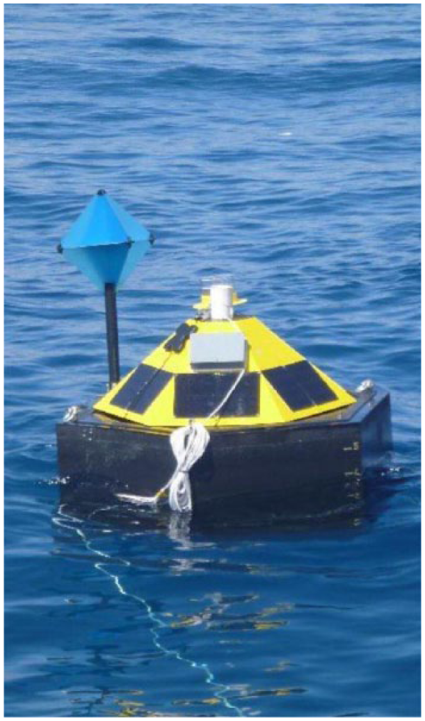
The heaving-buoy concept is another natural oscillator, similar to the pendulum concepts, the OWC and the mechanical pendulum. A buoy that is held entirely underwater or allowed to pierce the surface like a ship provides an upward buoyancy force. According to Archimedes’ principle, this force is equal to the weight of displaced seawater minus the weight of the shell of the buoy and any attached objects. The buoy is tethered to the seabed by a cable, or in one concept trialled in Australia, held from the top by a link connected to an independent frame. The cable must be connected to a moving part, such as a hydraulic cylinder or pinion that either directly or indirectly transduces the reciprocating motion to rotary motion to generate electricity. Furthermore, whatever system the cable or link connects to must possess appropriate stiffness, so that there is a restoring force returning the buoy to equilibrium after a wave displaces it; a mechanical spring is the simplest example of a restoring-force system. The natural frequency of the most elementary example of a completely submerged heaving buoy can be written as
where k is the ‘stiffness’ of the restoring-force system and m is the net mass (inertia) of displaced seawater (Figure 2(c)). The inertia m depends essentially on the size of the buoy and is reduced by any pre-tension in the restoring-force system. The power delivered increases with the stiffness, among other factors. It is clear by comparing equations (2) and (3) that the heaving-buoy concept offers more opportunities for design than the pure-pendulum concepts. Both m and k can be designed by the engineer such that
If the buoy is allowed to pierce the surface, the expression for
As noted in earlier sections, devices near to or piercing the surface generally benefit from the maximum in wave action at the surface. However, this exposes them to a greater risk of damage from storms, unless their buoyancy can be temporarily negated to ‘sink’ them to the bottom for safety, as with the BPS machine described in section ‘Mechanical-pendulum developments’.
Carnegie Wave Energy (CWE) (2015), based in Fremantle, Western Australia, began testing a heaving-buoy concept in 1999 (Figure 2(c)). The company’s original capital base was derived from the Western Australian mining industry, and it is listed on the Australian Securities Exchange (ASX), enabling capital raising from share-market investors. The company’s first design, denoted CETO1, was subjected to trials in 2006. The CETO concept is a spherical or spheroidal float, with the most recent designs constructed of steel.
The last-tested CWE design, CETO5 (detailed in Fievez and Sawyer, 2015), was funded in part by ARENA (CWE, 2015). It was tethered to the seabed by a cable, and mounted at the seabed joint was a hydraulic cylinder. Hydraulic fluid is pressurised on the upstroke as the buoy rises, flowing via a one-way valve into a pipeline to shore. As for the other technologies noted above employing valves, energy will be lost as fluid passes through the valves. The high-pressure fluid was stored in accumulator tanks from which it could be released to drive a conventional unidirectional hydraulic generator, which was grid connected. Low-pressure fluid exhausted from the generator was returned to the offshore cylinder via a second pipeline and second one-way valve, where it still had sufficient pressure to provide the restoring force returning the buoy to its lowest displacement.
The hydraulic cylinder with its buoy can be attached to and removed from a housing on the seabed, permitting recovery and maintenance. The hydraulic fluid was originally planned to be seawater, thus enabling an alternative use of the high-pressure water in a desalination facility; however, the properties of seawater were not optimal for the performance of the hydraulic system, so that desalination was delivered simply by sending the electricity generated to a conventional desalination plant. The buoy is 11 m in diameter, and a single device had an estimated peak output of 240 kW (CWE, 2015).
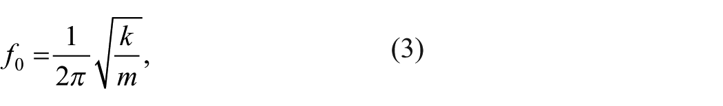
Three CETO5 units were built, and over 2015 progressively deployed in the ocean off Garden Island, Western Australia, about 40 km south of Perth (Figure 6(a)). The buoys were manufactured in a shipyard in Vietnam and transported to Perth for final fit-out, from which they could be towed the short distance to site. This array performed as planned, including a programmed removal and re-deployment of one of the units, demonstrating that routine maintenance was possible. At the end of the trial, all the units were removed as planned. This trial represents one of the longest-lived demonstrations of an array of WECs anywhere in the world (ARENA, 2016b).
(a) Carnegie Wave Energy CETO5 array in operation off Garden Island, Western Australia, in 2015; each 240 kW buoy is 11 m in diameter. (b) Artist’s impression of the Carnegie Wave Energy 1 MW CETO6 system.
The next machine in CWE’s programme, CETO6 (Figure 6(b)), has an estimated power output of 1 MW and is 22 m in diameter (CWE, 2015). Unlike its predecessor, the hydraulic system and electrical machine generating electricity will be inside the buoy, which like its predecessors is constructed using shipbuilding techniques. The on-board hydraulic generator will make the machines independent of onshore facilities (apart from a grid connection) but will require the internal systems to be resilient since access for maintenance will be infrequent.
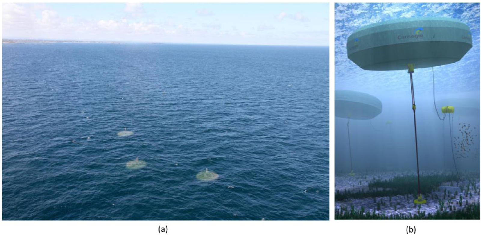
Aquagen Technologies, a Melbourne-based start-up company, tested a prototype heaving buoy in 2010 from the pier at Lorne, Victoria (AquaGen Technologies, 2014). In this concept, the buoys are surface piercing, and the cable is connected via an underwater pulley to a generator on a platform above the water (Figure 7); in the trial, the generator was on the pier. The buoy was 2.2 m in diameter and generated 1.5 kW. The advantage is that the only moving parts in the water are the cable and pulley, with no electromechanical systems or control on-board. The concept relies on a large array of small devices to generate economically significant power. At the time of writing, the company was seeking investment for further development.
Artist’s impression of the Aquagen Technologies concept; a single 1.5 kW buoy was trialled in Lorne, Victoria, in 2014.
Waverider Energy, an Adelaide-based company, was founded by Christian Gerlach. The company’s technology is an array of buoys held in a floating frame 111 m long, 13 m wide and 4 m high (McCaskill, 2014). Since there is a rigid frame, the buoys can be held from the top, rather than from below in other concepts. Since the frame is longer than the shorter wavelengths of swell, there is a relative movement between the frame and the buoys. The relative movement of the buoys turns a shaft via a mechanism. A machine rated at 500 kW was trialled in November 2011 off Adelaide (McCaskill, 2014). A clear advantage is that the joints converting reciprocating to rotary motion are not in the water, and thus a more complex and efficient mechanism is possible, although the mechanism is still in the saline-spray environment and potentially exposed to large forces. The company states that a larger prototype with a nominal 2 MW output is being developed (Waverider Energy, 2015).
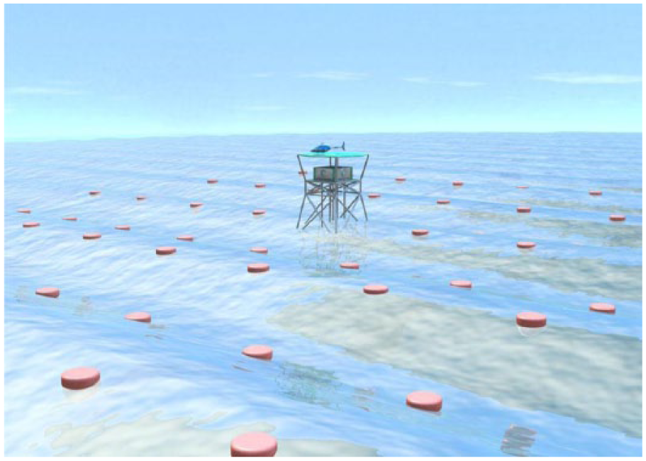
Protean Wave Energy, a Perth-based company, such as CWE, benefitted from the capital accumulated from mining in Western Australia. It is listed on the ASX. The Protean concept was invented by Sean Moore in 2004 (Griffith, 2015). The buoy, which appears to be roughly 1.5 m in diameter (Figure 8), is surface piercing and connected to a base on the seabed by multiple cables, which the company states offer the potential to extract power from >1 degree of freedom of motion (Proactive Investors, 2016). The cables turn pulleys inside the float which drive a pneumatic compressor. A counterweight is located in between the float and base; presumably, this provides a gravitational restoring force in addition to, or alternatively to, the stiffness of the compressed air. Since one-way valves are likely to be employed in the pneumatics, there is the potential for energy loss, just as with other technologies noted above using valves.
The Protean Wave Energy device under trial.
A single machine was trialled from a pier in Perth in 2015; analogously to the hydraulic-liquid transmission of the much larger CWS CETO5 system, the compressed air was piped onshore to turn a pneumatic generator. Similarly to the AquaGen design, the Protean design is intended to be installed in arrays, to overcome the issue of the very low–power output of an individual small machine. Furthermore, the small size affords economies of scale in manufacturing, and the presence of multiple units would allow redundancies permitting effective maintenance. An array of 30 machines is under development at Bunbury, Western Australia (Proactive Investors, 2016).
Pitching developments
To resonate a mechanical system requires its natural frequency to be matched, as described above. More generally, matching the natural frequency is just a matching of the temporal frequency; there is also the spatial frequency. Matching the spatial frequency requires the length of a rigid part of the machine to be a quarter of the wavelength, λ. The description of the resonators above implicitly assumes that their length is much smaller than λ, so that spatial-frequency matching is not required. However, a machine of sufficient length could resonate by matching its size to the wavelength as well as its natural frequency to the wave frequency. This category of ‘pitching devices’ (Falcão, 2010) operates at the surface where wave action is maximal. There are usually joints between rigid segments, and oscillation of the joints is converted into useful power by a variety of mechanisms. A pitching concept is being developed by Perpetuwave Power (2016; Figure 9), which was founded in 2003 in Brisbane.
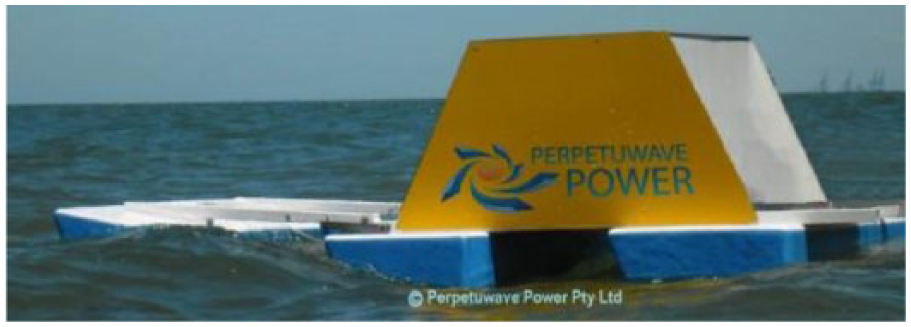
The Perpetuwave device under trial.
Non-resonating developments
Bombora Wave Power (BWP, 2016a), a Perth-based start-up company, was founded in 2011 by Shawn and Glen Ryan. Their concept, unlike all other Australian WEC devices trialled to date, does not rely on resonance. The underwater part of the machine sits on the seabed and is made of a flexible membrane divided into a number of cells (Figure 10). The cells are inflated with compressed air, but the system is designed to remain negatively buoyant and sit on the seabed. As wave crests pass over, the resulting high pressure forces air from cells through one-way valves into a plenum chamber, from which the compressed air drives a conventional unidirectional generator. Air exhausted from the generator into a second plenum chamber is then sucked back into the cells under the wave trough. As with the other concepts requiring one-way valves, there will be energy losses as air flows through the valves.
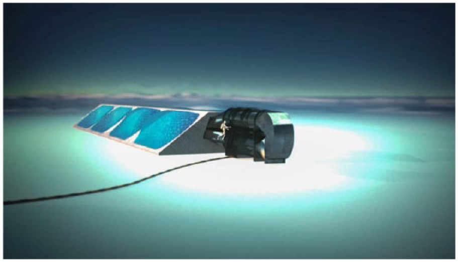
Artist’s impression of a Bombora Wave Power machine.
It is intended that the machine be composed of a large number of cells arranged in a row. Similarly to the ‘Wave Mill’ concept (section ‘Liquid-pendulum (oscillating water column) developments’), once the row of cells is longer than a wavelength, there will always be air simultaneously pushed out of some cells while being sucked into other cells. This offers the advantage of a generator that not only turns in the same direction but turns with a constant speed, at least for incoming waves that do not vary from wave to wave. In initial trials, the generator was onshore, but in future designs, the generator is intended to be underwater, with only a power cable connecting it to shore.
As noted earlier, wave motion and thus the pressure imparted by passing waves decrease with depth. In deep water, the pressure due to wave motion decreases exponentially with depth, which would render a bottom-mounted machine that does not reach the surface useless. However, as noted in section ‘Reasons for the diversity of WEC designs’, in shallow water (such that the depth is <1/20 of the wavelength), the pressure fluctuations are virtually unchanged with depth (Gill, 1982). Thus, the BWP device should function best in shallow water, with a depth of 5–15 m (BWP, 2016b). This is consistent with ocean swell having wavelengths of over 100 m, which as noted in section ‘Reasons for the diversity of WEC designs’ does occur on the Southern Ocean and southern Indian Ocean coasts of Australia (Behrens et al., 2012b).
The BWP device is thus a form of artificial reef, and its simplicity implies that it could be useful for coastal protection that assists in defraying its capital cost by profits from the sale of electricity, as noted by Falcão (2010) and Manasseh et al. (2017) and as discussed further in section ‘Discussion and conclusion’.
The absence of resonance means that the machine will not be able to draw in wave power over a region larger than its physical size, as noted in section ‘Reasons for the diversity of WEC designs’. Another way to express the absence of resonance is to note that the displacement of the cells will be the same as that of the water above them: There can be no amplification. Nonetheless, there is nothing inherent in the concept preventing it from being redeveloped into a resonator in the future. A number of parameters are available, such as the stiffness provided by the compressed air and the volume of air in accumulators, which may permit tuning of a future version.
Australian tidal energy
Resources
Regions of high tidal amplitude or strong tidal currents are most feasible for tidal-energy extraction. In the case of regions with large tidal amplitude, it is the potential energy that is exploited via structures such as tidal barrages. In regions of strong tidal currents, it is the kinetic energy that is exploited via free-stream turbines (Behrens et al., 2012a). High tidal amplitudes occur in locations where the tide is in resonance, which typically occurs when the natural oscillation frequency of a semi-enclosed body of water coincides with one of the astronomical forcing frequencies (Behrens et al., 2012a). Although a detailed assessment of Australia’s tidal energy resource has not been undertaken to date, Behrens et al. (2012a) note regions of greatest tidal height to be the north-west shelf, Broad Sound in Queensland and the northern coast of Tasmania. Regions where tidal currents are large include, for example, the eastern and western sides of Bass Strait, Torres Strait in northern Queensland and Kings Sound on the north-west shelf. This assessment was based on a coarse-resolution tidal model. Given the complexity of tidal flows (e.g. around headlands and in constricted passages), the estimates provided by Behrens et al. (2012a) are likely to have underestimated the available resource, and so further high-resolution assessment of Australia’s tidal resource is required.
Technologies
In contrast to the complex diversity of fundamental concepts observable in wave energy, tidal-energy technologies are more readily understood. Unlike the reciprocating flows of wave energy noted in section ‘Reasons for the diversity of WEC designs’, tidal flows, while they do reverse, are unidirectional for 6 hours. This allows conventional turbines to be used if the flow speed is high enough; it is only necessary to pivot the turbine through on the change from ebb to flow tides and back. Since most coasts do not enjoy tidal flows fast enough to turn a turbine of economic scale, variations in technologies centre on various strategies to extract power from low-speed flows. These are detailed in a companion article (Manasseh et al., 2017); the most common is the ducted turbine, which seeks to increase the speed passing through the turbine with a converging duct. In locations where speeds are naturally high enough, a free-bladed turbine is feasible. Manasseh et al. (2017) also note that the tidal barrage concept can capture all the tidal energy in a bay or inlet, by simply constructing a barrier.
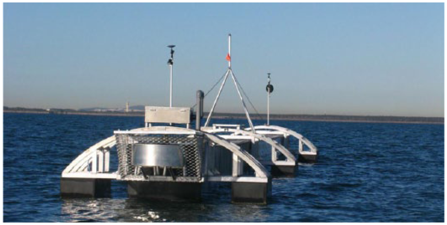
Atlantis Resources (AR, 2016) is a tidal-power developer originally founded in Brisbane. In 2002, AR tested its first tidal-power technology at San Remo, Victoria. The machine, called the ‘Aquanator’, was a caterpillar-track-like device with multiple blades able to operate irrespective of the flow direction (Figure 11). It was a unique solution to the low-speed flow problem. It was grid-connected and rated at 100 kW (AR, 2016). The narrow strait between San Remo and Phillip Island is the eastern of two entrances to Westernport Bay and has significant tidal flows. The western entrance provides access for commercial shipping to the port of Hastings, but the eastern entrance does not have such traffic.
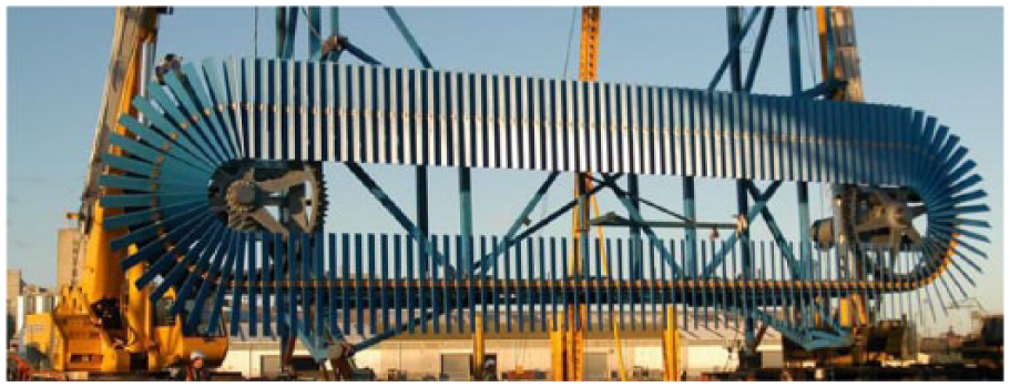
The Atlantis Resources 100 kW turbine tested in 2006 in San Remo, Victoria.
The company established operations in Singapore in 2006 ‘attracted by high quality R&D capabilities, as well as the integrity of the intellectual property protection laws’ (AR, 2016). In 2008, the 150 kW, grid-connected AN150 machine, replaced the ‘Aquanator’ machine at San Remo. The San Remo site was decommissioned in 2015. Since then, the company has developed more conventional ducted turbines and free-bladed turbines and has begun planning projects in Scotland, Canada and China. Its latest turbines are developed in collaboration with US multinational engineering firm Lockheed-Martin.
The company listed on London stock exchange in 2014, while retaining its headquarters in Singapore (Fiakas, 2016). The company has benefitted from significant financial support from the UK government. The commercial 400 MW MeyGen site at the northern tip of Scotland, the world’s largest tidal stream project, is nearing completion (MeyGen Limited, 2016). This site has tidal flows of making the conventional AR turbines most suitable for its plans (Fiakas, 2016).
Elemental Energy Technologies (EET) is a Sydney-based developer of tidal turbines, founded in 2007 by Michael Urch. It tested its ducted turbine, the ‘Sea Urchin’ (Urch, 2013) at Newcastle, NSW, Australia, in 2011. The machine was rated at 2 kW. Further tests occurred in India, at the Defence Research and Development Organisation. The device was manufactured under licence from EET by Indian company Kirloskar Integrated Technologies Limited in Pune, India. In 2012, Tenax Energy signed a Memorandum of Understanding to develop a 2 MW tidal-power plant in the Clarence Strait between Darwin and Melville Island that would use EET turbines. At the time of writing, the project has not yet progressed. Meanwhile, EET was absorbed by another company, Mako Turbines (2015), which is developing another turbine, the ‘Mako’; this being a free-bladed turbine. Many more Australian tidal-power trials have taken place; these are summarised in Table 1.
Other marine renewables
Ocean-current power, as available from large-scale oceanographic flows such as the major western boundary currents of the World’s oceans, is described in Manasseh et al. (2017). The most significant such resource for Australia is the EAC, which flows along the coast of Queensland and New South Wales. Griffin and Hemer (2010) note the EAC flows as a fast narrow jet along the upper continental slope between Fraser Island and northern NSW, at speeds in excess of 2 m s−1 in the vicinity of the 1000 m-deep contour. Beyond this stretch of coast, the EAC is an unstable meandering flow best characterised as a series of swirling eddies. Interest in the EAC as a source of energy is longstanding, with interest extending back to at least the early 1980s (Thomson, 1980). However, Griffin and Hemer (2010) note the low power density of these flows, thus requiring very large–diameter devices to extract sufficient power to make it a viable prospect. The total width of the fast region of current is about 20 km, and thus, resource availability is likely heavily constrained relative to Australia’s needs (Griffin and Hemer, 2010).
OTEC is described in Manasseh et al. (2017). It requires a surface water temperature of at least 20°C, which is found only in the tropics. Since a pipeline to depths approaching 1000 m is also required, OTEC is most viable where continental shelves are narrow or on isolated islands. Such locations are found on the coast of far north Queensland; Behrens et al. (2012a) noted potential sites 100 km off the North Queensland coast, 150 km North of Cairns. Locations such distances offshore introduce economic disincentives. There has been a suggestion of OTEC development in this region (Ridd, 2005), but no developer has yet come forward.
Salinity gradient energy conversion (SGEC) is detailed by Kempener and Neumann (2014). In very simplistic terms, it could be described as the reverse of desalination. In desalination, energy is supplied to turn saline water into freshwater. The reverse process releases energy as freshwater is allowed to dilute saline water. Effectively, this energy was ‘stored’ in the freshwater when the sun’s heat evaporated it to form rain. In the southern part of Australia, there is sometimes a shortage of large quantities of freshwater, which has led to the construction of desalination plants servicing major cities. Thus, SGEC may be more useful in the tropical North, where large volumes of freshwater flow out to sea during the wet season. Behrens et al. (2012a) also propose a combination of desalination and SGEC as a form of energy storage.
Discussion and conclusion
Australia is endowed with every form of marine renewable energy resource: Wave energy, tidal energy, ocean-current energy, ocean-thermal energy and salinity-gradient energy are available. Due to its geographical location, the continent has highly energetic wave resources in the south and warm tropical seas suitable for OTEC in the north. A huge region with high tidal range is present in the north-west, and a major western boundary current runs along the east coast. The United States is the only other national jurisdiction possessing all classes of marine renewable energy resource.
The majority of the population is concentrated in cities on the coast, so that electricity infrastructure is distributed coastally. However, there are great distances between population centres, and the port facilities and workforce able to construct, install, operate and maintain maritime technologies are not necessarily within easy reach of resource locations. As one example, Australia’s most energetic wave resources lie off the coast of SW Tasmania, a wilderness area with almost no population centres. In another example, the high tidal ranges of NW Western Australia occur over a vast coastline that is virtually unpopulated, and while the population that is there does need energy, the absolute amount of energy needed locally is very small. The remote nature of north-west Australia has not been an issue for major petrochemical and mining developments which have occurred in the same region. However, those developments service enormous export markets, not domestic markets, and are pursued by very large, well-established corporations that are able to construct entire towns to service their developments.
We note that the protection of the coast from waves is of on-going relevance (Abanades et al., 2015), particularly in the context of other alterations that might occur due to climate change (Manasseh et al., 2017). The use of WEC arrays for coastal protection, up to now constructed only in Europe in the form of breakwaters that generate power (Arena et al., 2013; Torre-Enciso et al., 2010), should be considered in Australia. This has been proposed for the Bombora device (Ryan et al., 2015). Unlike solid sea walls, WEC arrays offer the ability of removing power from waves without completely eliminating them. Moreover, the power removed could be altered to suit the circumstances of the day: ‘tuneable’ coastal protection. This may permit the reduction of some extremes without necessarily inducing the environmental impacts of impenetrable infrastructure. Furthermore, it has already been noted that significant reductions in the levelised cost of electricity would occur if the imperative to protect the coast provides a share of the cost of constructing the infrastructure (Falcão, 2010). Correspondingly, the sale of electricity could offset the cost of servicing debt needed to construct coastal-protection infrastructure.
The 2014 Oceanlinx incident illustrates some of the issues facing WEC technology, some universal, some specific to Australia. The incident was nothing to do with the technological concept; as noted, OWCs have been operating in the ocean for over 130 years and generating electricity for over 60 years. A universal issue is the small scale of firms developing concepts, which as noted in section ‘Reasons for the diversity of WEC designs’ is possible due to the ease of developing unique IP, itself a fundamental feature of the physics of waves and of engineering. However, deploying large devices in an ocean environment that is, by definition, highly energetic, is usually the preserve of large companies such as those in the petrochemicals industry. Such large companies have the capital and resources to undertake risky operations over long time frames, and to recover from setbacks; small firms do not. The incident itself was due to a combination of the need for a large device, in order to resonate at ocean wave frequencies that are particularly low on the southern Australian coast, and the long distances between port facilities and deployment sites typical of Australia. Furthermore, the small size of the company, itself a feature of the ease with which IP can be created in wave power, may have limited its deployment options.
The example of AR is also instructive. Once the company had successfully tested its technology in Australia, it moved to Singapore and then listed in London. It has used the Australian site to build expertise in tidal technology testing and development but ceased operations in Australia once appropriate business prospects emerged. It now contracts out prime engineering design to a major multinational engineering concern. It supplies equipment under tender to government-supported power generation initiatives. The company’s base is geographically closer to both tidal sites on both sides of the North Atlantic and to sources of capital to finance further operations. In practical terms, it has ceased to be an Australian developer.
It is important to understand the principles underpinning the Australian developments and understand these principles in their geographical context. We have seen that details such as the depth of the water and the frequency and wavelength of the prevailing ocean swell may make some wave-power technologies best for some locations, while nominally competing technologies are best for other locations. If the need to protect the coast is included, still other wave-power technologies operating best in shallow water may be more viable. Similarly, some tidal technologies may be viable in Australia’s tropical North West, where the great width of the continental shelf assists the creation of high tides, while reducing the wave resource. Where wave and tidal resources may be less viable, ocean-current power may provide a marine renewable energy option such as along the coasts of south-eastern Queensland and northern New South Wales. OTEC may be a viable option in the tropics.
In summary, Australia is an excellent testing ground for all classes of marine renewable energy technologies. As Australia, along with all other nations, seeks to decarbonise its energy supplies, further development of its immense marine renewable energy resources will occur. As noted in section ‘Introduction’, examples of levelised costs of electricity for wave, tidal and OTEC resources are given in Table 5 (section ‘Engineering and economic efficiencies’) of a companion article (Manasseh et al., 2017). These indicated that estimates of marine-renewable-energy levelised costs of electricity in the year 2030 were still higher than present-day wind costs. Moreover, the fairly small national population means that technology-development companies will struggle to grow to a viable size if they focus solely on meeting local electricity demand. Coastal protection is one aspect where wave-power technologies in particular could rapidly reach economic viability, due to the sharing of infrastructure costs, and a nation whose developers can master tuneable coastal protection may be able to export expertise.
A paradigm for large growth may be export of marine renewable energy. In 1974, Salter suggested that WECs may be used to generate and store hydrogen. Whether or not that particular suggestion is viable, export of fossil fuels from Australia is presently a huge industry with its infrastructure already focused on maritime export. James (2011) suggested export of electricity by undersea transmission; although such infrastructure does not exist, port and shipping infrastructure does exist. Thus, research into ways of storing and exporting marine renewable energy is indicated.
Footnotes
Declaration of Conflicting Interests
The author(s) declared no potential conflicts of interest with respect to the research, authorship, and/or publication of this article.
Funding
The author(s) disclosed receipt of the following financial support for the research, authorship and/or publication of this article: R.M. is grateful for the support of the Australian Renewable Energy Agency (ARENA), via grant ERP A00575. K.L.M. and M.A.H. are grateful to ARENA via grant ERP A00521. Information on tidal energy trials in Australia was kindly provided by William Hollier of Engen Institute.