
Abstract
Harvesting marine renewable energy remains to be a prime focus of researchers across the globe both in environmental and in commercial perspectives. India is blessed with a long coastline, and the seas around Indian peninsula offer ample potential to tap various ocean energy forms. National Institute of Ocean Technology carries out research and various ocean energy technologies, out of which harnessing kinetic energy in seawater currents is one. This article presents the open sea trials recently carried out on National Institute of Ocean Technology’s cross-flow hydrokinetic ocean current turbine in South Andaman. The turbine was designed to generate 100 W electricity at 1.2 m/s current speed and was built in-house. The turbine was initially tested in a seawater channel and then was deployed in Macpherson Strait in Andaman. It was fitted below a floating platform designed especially for this purpose, and the performance of the turbine was continuously logged inside an on-board data acquisition system. The trials were successful and in line with computations.
Keywords
Introduction
Ocean currents are driven by wind and solar heating of the waters near the equator, although some currents result from variation in water density and salinity. Ocean currents are much slower compared to wind speeds. However, water is about 835 times denser than wind, so a smaller water flow can be equivalent to wind with extremely high velocity. Energy can be extracted from such ocean currents using submerged turbines that capture energy from hydrodynamic lift and drag forces.
Different configurations of turbines are considered for harnessing kinetic energy in ocean currents as shown in Figures 1 and 2 (Khan et al., 2008). Axial flow turbines have underwater version of wind turbines, whereas cross-flow turbines use straight blades that are parallel to axis or blades with helical shape. Blades of the cross-flow turbine have cross section of a streamlined hydrofoil. Axial flow turbines reverse the sense of rotation or they need to be reoriented whenever the current direction reverses, whereas cross-flow turbine design allows them to revolve in the same sense of rotation. Hence, straight bladed cross-flow configuration is considered for designing the turbine under consideration.
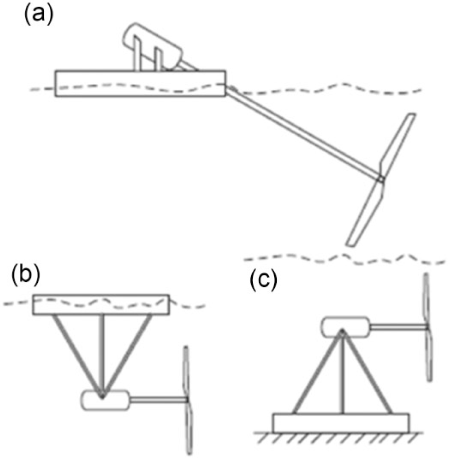
Axial flow water turbines: (a) inclined axis, (b) float mooring and (c) rigid mooring (Khan et al., 2008).
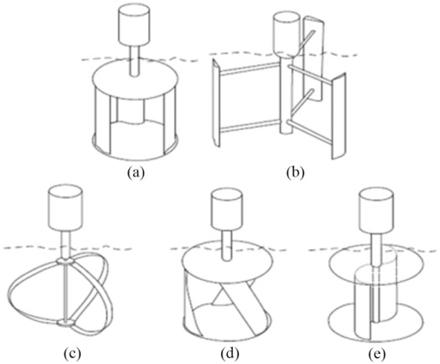
Sketch of different vertical-axis turbines: (a) SC-Darrieus, (b) H-Darrieus, (c) Darrieus (curved blade), (d) Gorlov and (e) Savonius rotor (Khan et al., 2008).
The turbine design included analysis and optimization using computational fluid dynamics principles. Then the turbines were tested in laboratories and a seawater channel in North Chennai. As a result of extensive studies, National Institute of Ocean Technology (NIOT) recently carried out successful sea trials in Andaman and Nicobar Islands on a small cross-flow hydrokinetic turbine which was designed and developed in-house. This article presents a brief account of the trial and the performance of the turbine.
Sizing for 100 W electrical power generation
The total input kinetic energy in a stream of water flowing at velocity V (Gorlov, 2001) can be calculated by
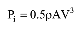
The turbine performance is based on the turbine parameters such as number of blades (z), solidity ratio (σ) and blade profile. The number of blades was selected as three (Castelli et al., 2012) where each blade is placed at an interval of 120°. The solidity ratio is defined as follows
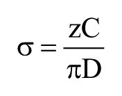
where C is the chord length of the blade and D is the diameter of turbine.
The design calculation was based on the performance of straight bladed–type turbine with a coefficient of performance of 0.3 at tip speed ratio of 1.5 from the experimental study of Shiono et al. (2002). Here, the coefficient of performance is the ratio of the gross mechanical power output of turbine to the input power and the tip speed ratio is the ratio of the blade speed to the seawater current speed. The overall transmission efficiency that includes the mechanical transmission and the electrical conversion was assumed at 70%. The turbine was designed to produce an electrical power output of 100 W at approximately 1.2 m/s seawater current speed. Blade profile of NACA 0018 was selected for the blades. However, a higher solidity ratio was chosen to improve self-starting characteristics of turbine and its performance in low current speeds (NIOT Report, 2015). The following assumptions were made for designing the turbine blades:
Design water velocity, V: 1.2 m/s;
Number of blades, z: 3;
Density of seawater, ρw: 1020 kg/m3;
Transmission efficiency, ηt: 0.7;
Generator efficiency, ηg: 0.7;
Length of turbine, L: 1 m;
Tip speed ratio at peak power, λ: 1.5;
Solidity ratio, σ: 0.36.
The three-dimensional (3D) model of the turbine with 0.8 m diameter and 1 m length is shown in Figure 3. The assembled structure of the turbine can be seen with the shaft and blade arms. One blade was held between two blade arms, and a total of six blade arms were used to fit three turbine blades with an angular spacing of 120°.
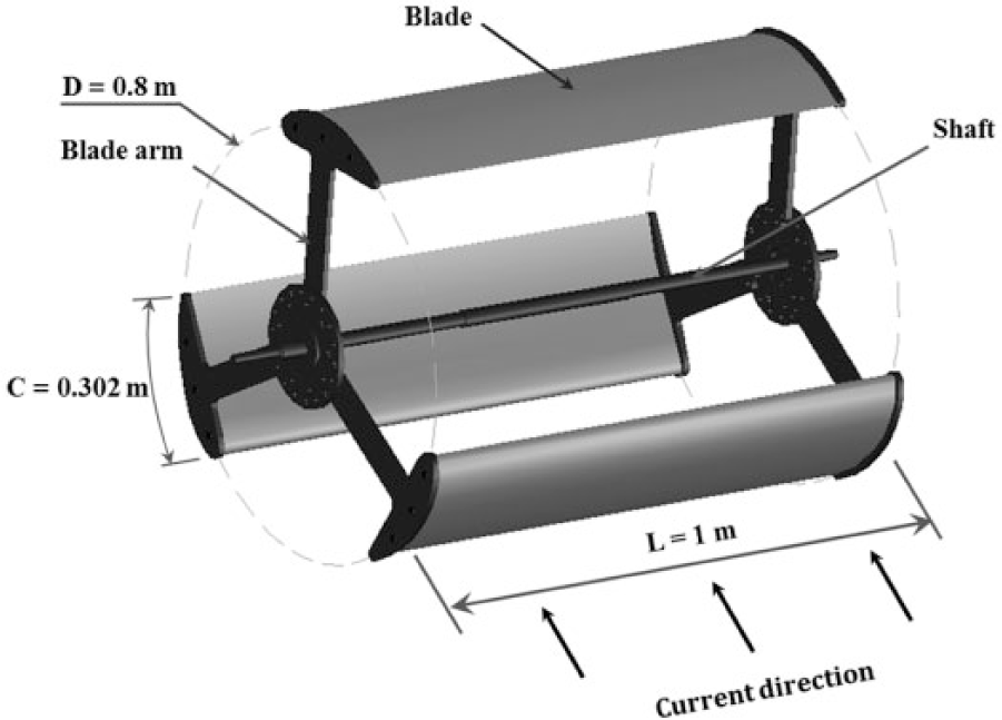
Geometrical model of φ 0.8 m × 1 m straight bladed turbine with NACA 0018 profile at solidity ratio of 0.36.
In towing tank testing, it was found that the cut-in speed of the turbine was 0.8 m/s. Any specific cut-out speed was not considered while designing the turbine. The transmission was designed to transmit 70 N m torque, which is 50% higher than peak torque at design current speed.
A two-stage timing belt drive was used to couple the turbine to the electrical generator. An electrical alternator of rated speed of 750 r/min was chosen in order to allow 50% increase in turbine speed above design speed. The belt drive and the alternator assembly were placed inside an underwater enclosure along with instrumentation.
Instrumentation and data acquisition system
Two on-board data acquisition (DAQ) systems were employed for data redundancy. One was placed on the floating platform with minicomputer for data logging and the other was placed inside the underwater enclosure as shown in Figure 4. The enclosure housed voltage sensor and current sensor. A rectifier converted the alternating current to direct current. Solar photovoltaic panels were used to charge the battery for powering the instruments used in the system. Solar charge regulator was also placed near the minicomputer inside enclosure. The DAQ system had two subsystems, namely, Compact Reconfigurable Input and Output (cRIO) System and wireless system.
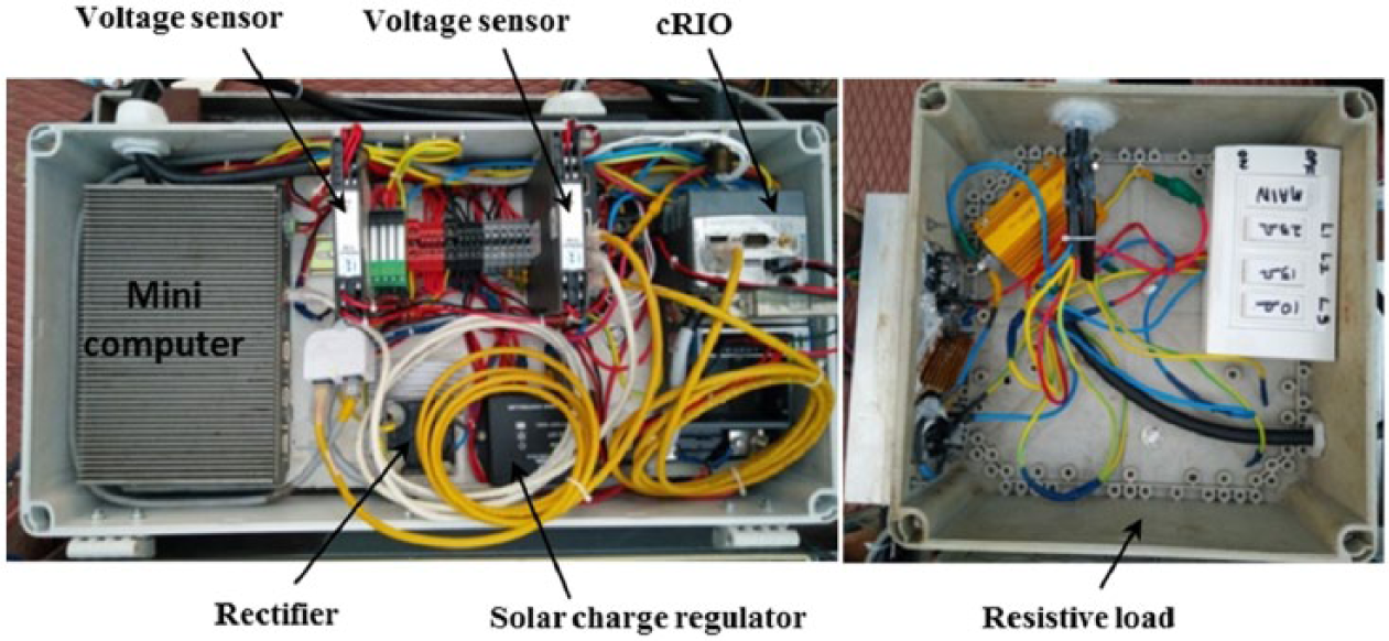
Electrical and instrumentation system placed inside water proof enclosures.
The cRIO was programmed using LabVIEW-2015 in FPGA (Field Programmable Gate Array) mode. It was used along with multichannel 4–20 mA analogue input modules. Signals of 4–20 mA from the speed sensor, V&I sensors of PMSG (permanent magnet synchronous generator) and V&I sensors of PV cRIO-9014 were processed and stored in real time. cRIO was programmed also for the real-time plots for monitoring the performances of the current turbine. The CPU of cRIO was programmed to send the data simultaneously to the on-board data reception station on board watch-keeping boat through radio frequency (RF) communication. Instruments placed securely inside different water proof enclosures are shown in Figure 4.
Testing of turbine at seawater channel
Figure 5 shows the turbine during seawater channel testing at 1.2 m/s seawater speed as measured by Acoustic Doppler Current Profiler (ADCP). For the prevailing water speed, the peak electric power output of 108 W was obtained at 34 r/min turbine speed. After accounting for the losses in mechanical transmission and alternator – estimated as 25% each as a result of separate exercise – the net and gross mechanical power output was estimated at 130 and 156 W, respectively. The coefficient of performance of the turbine (Cp) was found to be 0.23 at a tip speed ratio of 1.2 as seen in Figure 6. Subsequently, the turbine was considered suitable for open sea testing and Andaman was selected as the location.
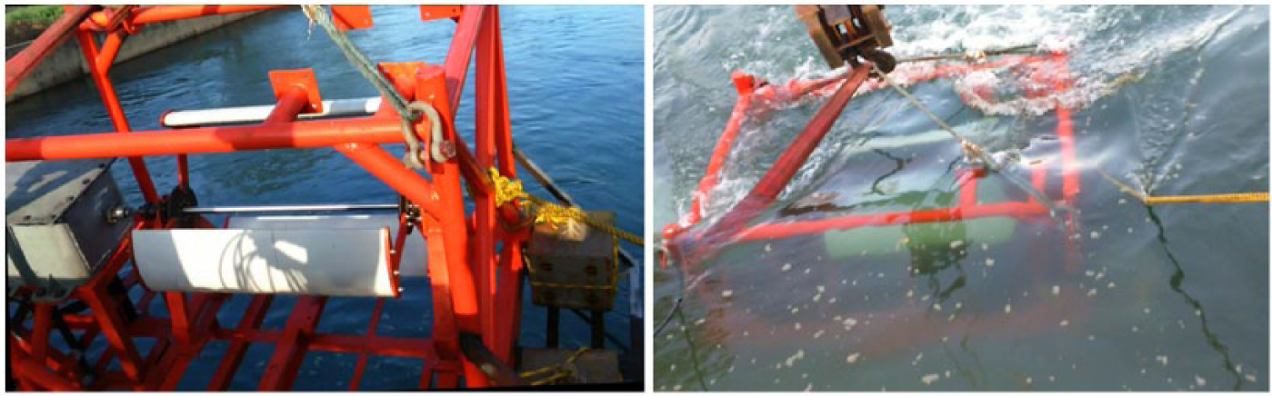
Testing of φ 0.8 m × 1 m straight bladed horizontal axis turbine at NCTPS channel.
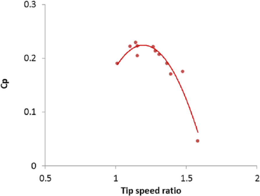
Performance of φ 0.8 m ×1 m straight bladed horizontal axis turbine in NCTPS channel at 1.2 m/s.
Floating platform for turbine testing
The floating platform for suspending the turbine was designed as shown in Figure 7. The platform design was analysed to determine deflections and utilization ratios for all possible loading conditions. The design requirements were (a) maximum operational depth of 2 m from water level, (b) provision of A-frame for lifting and lowering the turbine with base frame (1 tonne), and (c) design for drag, mooring effects, operational loads and all possible load combinations. Structural analysis software STAAD Pro was used to analyse various configurations of the platform.
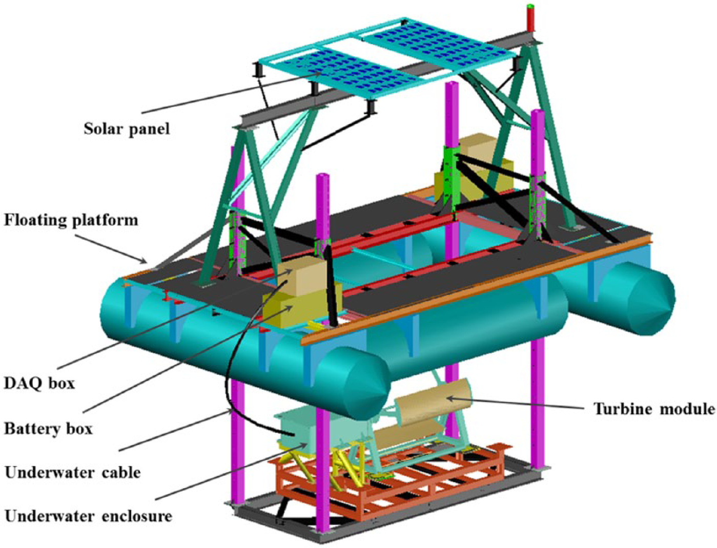
Schematic of turbine system with floating platform.
The hydrostatic stability of the platform in static and towing conditions was studied for different positions of the turbine with respect to water level (1.4, 1.2, 0.7, −0.2, −0.3, −0.8, −1.3 and −2.0 m). The turbine position at 1.4 m above the water level was considered for towing condition. The platform was found to be stable as the estimated transverse and longitudinal metacentric heights were found to be 10 and 3.8 m, respectively, with the turbine at −1.3 m (below water level). The metacentric height slightly reduced for the turbine position above water level due to marginal increase in the distance of centre of gravity from keel. But it was still safe.
Figure 8 shows the completed floating platform placed in the water near jetty for testing its stability. The platform had a provision to lower the turbine from the central moon pool till the turbine shaft reached a depth of 2 m from the water level. The four columns were lifted or raised or held in desired position using two chain-pulley blocks hooked to the either side of A-frame. The floating platform was also used to house the solar panels, batteries and data logging system.
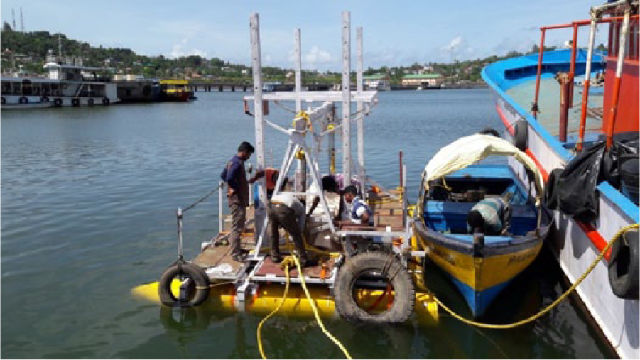
Floating platform lowered in water from Fisheries Jetty in Port Blair.
Deployment of turbine at Andaman Island
The Macpherson Strait connects Bay of Bengal on West and Andaman Sea on East. NIOT had earlier carried out seawater current measurement at one location for a very brief period. These measurements indicated that the peak currents often exceeded 1.2 m/s and were influenced mainly by tide. Also the wave action near Rutland Island was negligible (NIOT Report, 2013). Hence, the location was chosen for carrying out open sea trial. The turbine was towed to the location marked in Figure 9.
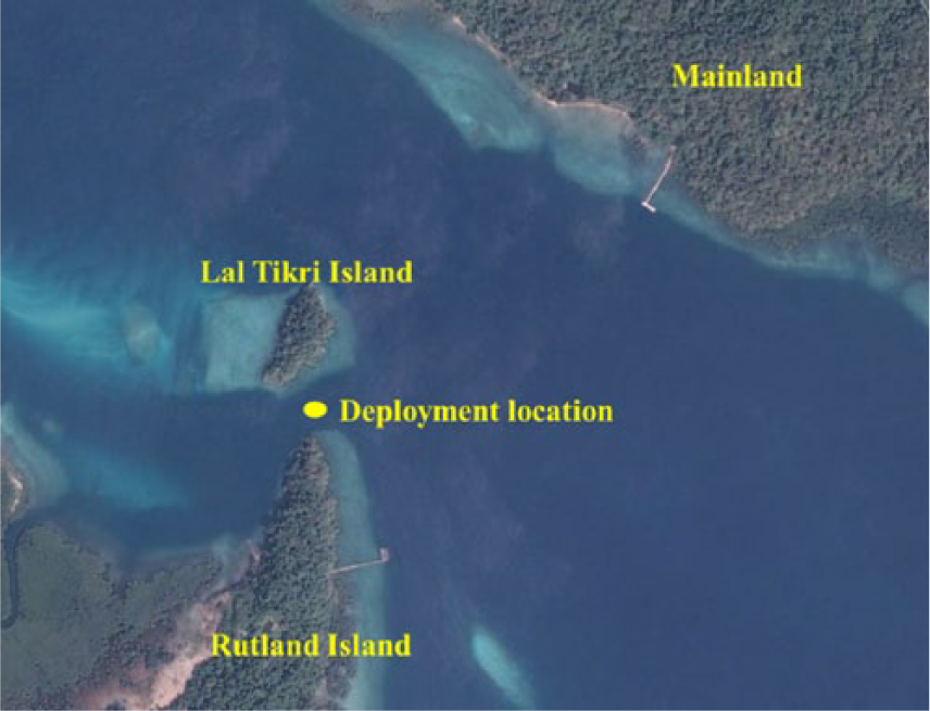
Deployment location of turbine in Macpherson Strait.
The towing route from main bay in Port Blair to the test location was 48 km long, and a total of 18 hours of time was taken for towing. Upon reaching the site, the instrumentation was readied and the turbine was lowered to check all systems during low tide currents at a nearby jetty. The turbine responded well and started rotating while the current at 2 m depth was measured as 0.9 m/s. On the next day, it was lowered to the depth of 2 m from water level. This location is along the smallest section on the ~20-m-deep channel between Rutland Island and the smaller Lal Tikri Island.
The turbine started generating electricity whenever current speeds were above 0.8 m/s and gave consistent performance throughout the trial period. Figure 10 shows the photographs of deployed turbine platform taken at various times. The glowing lamps seen in photographs are powered by the electricity generated by the turbine.
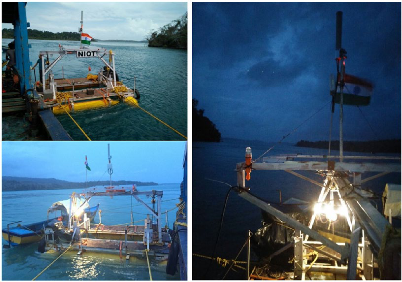
Turbine producing electrical power and the same being used for lighting the bulbs.
Results and discussion
The exercise generated valuable data about the performance of the turbine and the currents at the test sites via direct measurements. The turbine exhibited self-rotating characteristics whenever the seawater current speed crossed the cut-in speed of 0.8 m/s. The maximum electric power reported during the trial was 304 W. Figure 11 shows a representative time series of rectified electric power output from turbine recorded on 7 June 2016. During the trial, the turbine functioned at a coefficient of performance of 0.22 that matched the earlier test results. The turbine was retrieved after successful completion of the trial.
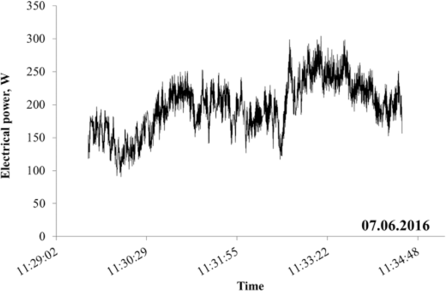
Typical 5-minute data of electrical power generation recorded on 7 June 2016 during the sea trial.
Conclusion
A 0.8-m-diameter turbine with 1-m-long blades was designed to generate 100 W electrical power at seawater current speed of 1.2 m/s. The turbine was fabricated and was made to undergo all possible stages of development. It successfully generated the design power output in a seawater channel. Following this success, this turbine underwent rigorous testing in Macpherson Strait in South Andaman. At this location, the turbine when suspended below water surface from a specially designed floating platform not only generated the requisite power but also recorded a power output as high as 304 W – when the currents exceeded 1.8 m/s – surpassing its design power of 100 W by a huge margin. The data logging system, Wi-Fi data transmission system and turbine control system performed satisfactorily. The turbine was found to be self-starting at speeds above 0.8 m/s. The coefficient of performance was estimated to be 0.22 which matched earlier testing results very well. These tests pave the way for scaling up of off-grid units for remote coastal locations.
Footnotes
Declaration of Conflicting Interests
The author(s) declared no potential conflicts of interest with respect to the research, authorship, and/or publication of this article.
Funding
The author(s) disclosed receipt of the following financial support for the research, authorship, and/or publication of this article: The work presented in the article was funded by Ministry of Earth Sciences, Govt. of India.