
Abstract
Marine renewable energy has the potential to solve both the energy-security and coastal-protection problems affecting coastal societies. In this article, the potential benefits arising from the combination of marine renewable energy technologies with infrastructural needs for coastal protection and other local needs are analysed. Classifications of technologies are developed to inform future coastal planning. Explanations of the resources and technologies are presented in layperson’s term. The threat of coastal inundation under climate-change scenarios is a major global issue. The investment in new infrastructure demanded by cities, ports and communities at risk of inundation could very substantially reduce the levelised cost of electricity from renewable sources, provided the infrastructure is designed with the dual purpose of power generation and coastal protection. Correspondingly, the sale of electricity from such infrastructure could defray the long-term cost of installing coastal protection. Furthermore, many marine renewable energy technologies provide a platform on which other forms of renewable energy generation could be mounted. It is noted that the complex geophysical and engineering issues arising from this opportunity must be assessed considering socio-economic factors.
Introduction
The sea has been proposed as a source of renewable energy for centuries, with the first patent in ocean-wave power filed in 1799 (Falcão, 2010). There was a great increase in research and development following the 1970s oil crisis. The present boom in marine renewable energy (MRE) research and development began in approximately the late 1990s, and today there an estimated 250 wave-energy developers and 120 tidal-power developers (The European Marine Energy Centre, 2016a, 2016b). Most attention has focussed on the generation of utility-scale electricity and the complex engineering and financial challenges of developing this form of alternative energy supply. Here, decisions on device installation are made by power utilities, who are well-informed and well-equipped to make technical judgements. Usually, decisions can be made based on the levelised cost of electricity (LCOE; see, for example, Hemer et al., 2016). Furthermore, much attention has focussed on developments in Western Europe, North America, Japan or Australia, where it is assumed that utilities will be making decisions based on national- or regional-level criteria, albeit with due attention to local environmental impacts.
However, it is possible that the greatest uptake of marine renewables will occur at the local community level. There are a number of factors that make marine renewables special at the local community scale:
Isolated island or coastal communities have a particular need for energy supplies that are decarbonised, since fossil fuels must be transported to them, often at great cost. For such societies, energy from the sea is a logical choice.
Coastal communities are at the greatest risk of climate change–induced inundation (e.g. Menéndez and Woodworth, 2010), and thus have the greatest motivation to install flood-mitigation infrastructure that can also generate useful power.
MRE systems are suitable for modularisation, such as wind power, and many small units could be combined to create a large ‘farms’ or arrays. A small community could begin with a single unit.
The many forms of MRE, and the many ways of classifying and assessing them, confounded by the natural imperative for private technology developers to promote only their own technology, is a source of confusion for laypersons – and indeed for many experts. These factors suggest that a clear exposition of the benefits and issues of MRE, written in laypersons’ language, together with criteria for assessment of technologies, could empower coastal communities to take the lead in MRE. In this review, most though not all examples are from India and Australia. Both nations have significant MRE resources and together encompass the complete spectrum of coastal communities and their needs.
This article is organised as follows. Section ‘Needs for coastal protection in changing climate scenarios’ explains the need for coastal protection, one of the main potential economic drivers to integrate MRE sources with coastal infrastructure. Section ‘Resource assessment techniques for the major MRE classes’ outlines the resources available in the major forms of MRE, wave and tidal energy; the less-widespread forms of marine renewables are described in the following section along with the technologies. Section ‘Classification of technologies’ introduces the technologies in detail, focussing on techniques for classifying the technologies in the context of decision-making by coastal communities; engineering details of the technologies are detailed in a companion article (Manasseh et al., 2017). Section ‘Experience from MRE developments in coastal communities’ describes some experiences of coastal communities hosting MRE technologies. Section ‘Engineering and economic efficiencies’ briefly introduces engineering and economic assessments of marine renewables, and section ‘Discussion’ discusses decision-making in the coastal-community context and presents a suggestion of a decision-making process.
Needs for coastal protection in changing climate scenarios
Globally, around 10% of world’s population (a little under half a billion people) lives in the 2% of land that is below 10 m elevation (McGranahan et al., 2007) with much of this population focussed in Asia (Dasgupta et al., 2009; Handmer et al., 2012). In terms of productivity, it is estimated that about a trillion US dollars of gross domestic product (GDP) is produced within about 1 m of present mean sea level (Anthoff et al., 2006).
Changing global climate is causing a range of consequences that pose significant threats for coastal zones. Coastlines are highly dynamic, shaped by hydrodynamic processes including wind-waves and storm tides (the combined sea level arising from the storm surge and the astronomical tide), that can cause erosion (e.g. Harley et al., 2011) or deposition of sediments (e.g. Smithers and Hoeke, 2014 and references therein) depending on coastal geomorphology and storm characteristics. Increasing anthropogenic emissions of greenhouse gases are trapping more heat energy in the atmosphere and raising global temperatures, increasing the melt rate of glaciers and the icesheets of Greenland and Antarctica, thereby contributing to sea-level rise. In addition, over 90% of the heat accumulating in the atmosphere is absorbed into the oceans, raising ocean temperatures and sea levels through thermal expansion (Church et al., 2013). Sea levels have risen about 20 cm over the past 100 years (Church et al., 2013), increasing the frequency of sea-level extremes (Menéndez and Woodworth, 2010).
The increase in greenhouse gases is also driving changes to global circulation patterns. Various metrics indicate a widening of the tropical regions of the earth (Seidel et al., 2008) and an associated poleward shift in storm tracks since the 1970s (Hartmann et al., 2013) together with a strengthening of the mid-latitude westerlies (Young et al., 2011) and wave heights, particularly in the southern ocean (Hemer et al., 2010; Young et al., 2011). Under future climate changes, the annual mean significant wave height (Hs) is projected to undergo a decrease in over 25.8% of the global ocean mainly in the boreal winter. However, an increase in Hs is projected over 7.1% of the globe, mainly in the southern ocean during the austral winter. This increase may impact distant coastlines as the increased wave energy propagates as swell into other ocean basins producing a projected increase in annual mean wave period of approximately 30% (Hemer et al., 2013). An increase in wave energy arriving at exposed coastlines may lead to an associated increase in erosional impacts on these coastlines, which will be further exacerbated by sea-level rise. Added to this, population growth, economic growth and urbanisation in the coastal zone will increase exposure to physical coastal hazards and impacts (Hanson et al., 2011). For example, they estimate that for the 136 port cities with more than 1 million inhabitants, the number of people exposed to a 1-in-100-year extreme sea level will increase from 39 million in 2005 to 59 million by 2070 through a 0.5-m rise in sea levels alone and to 148 million if socio-economic development associated with UN medium population projections is assumed.
The effectiveness of particular adaptation strategies such as building sea walls and renourishing beaches has been assessed using a coastal systems model that integrates the biophysical and socio-economic impacts of sea-level rise (Hinkel et al., 2013). They estimate that upgrading coastal defences and nourishing beaches would reduce the impacts of sea-level rise by roughly three orders of magnitude, suggesting substantial benefits are to be realised through coastal adaptation. Following on from this work, Hinkel et al. (2014) assess that 0.2%–4.6% of global population is expected to be flooded annually in 2100 under 25–123 cm of global mean sea-level rise. The associated losses are expected to by 0.3%–9.3% of global GDP annually. The cost of building and maintaining coastal protection in the form of dykes is estimated to be US$12–71 billion per annum in 2100, but this is less than the cost of damages that are avoided.
No studies to date have specifically examined the potential co-benefits that wave-energy converters (WECs) or other forms of MRE could have on coastal systems through the reduction in wave energy impacting the coast. Further research on this topic is therefore warranted.
Resource assessment techniques for the major MRE classes
Wave energy
Wave energy is fundamentally wind energy (Figure 1). Winds are created from the difference in solar heating between the Equator and Poles, which coupled with effects due to the Earth’s rotation drives the atmospheric circulation (Gill, 1982). As long as there is heat from the Sun and the Earth continues to rotate, strong, steady, westerly winds will be an inevitable feature of the mid-latitude regions of the Earth. It is these mid-latitude winds, averaged over vast reaches of our planet’s ocean basins, that create the highest energy and lowest variability waves: ocean swell. The average swell comes from the south-west in the Southern Hemisphere and the north-west in the Northern Hemisphere. It impacts all coasts in the mid-latitudes exposed to ocean to their west, such as the southern and western coasts of Australia and New Zealand, Chile, Canada and the Northwestern United States, South Africa and the North Atlantic coasts of Scotland, Ireland, south-western England, north-western France, Spain, Portugal and Morocco. The processes creating the swell, which we loosely call ‘averaging’, also reduce variability. In the Australian context, it has been estimated that wave energy has one-third the variability of wind energy (Behrens et al., 2012).
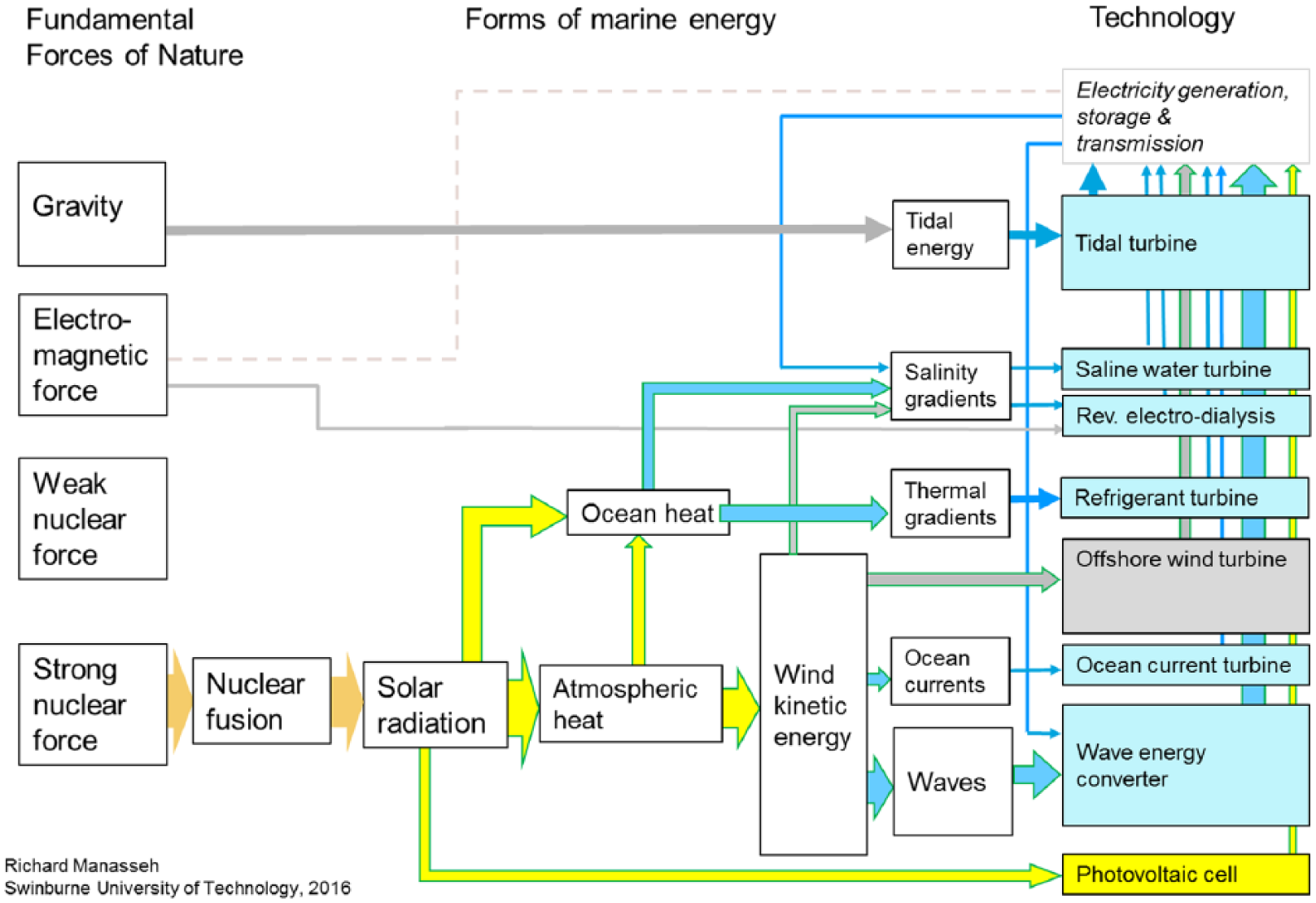
The origin and transformation of various forms of marine renewable energy. The two feedback loops represent the ability of some types of wave-energy converter to store energy in hydraulic- or pneumatic-pressure accumulators and the ability of salinity gradients to store energy via desalination processes.
Furthermore, the swell propagates for thousands of kilometres over ocean basins with little loss of energy until a continental shelf is encountered. This contributes to potentially useful wave heights on some coasts in the subtropics or tropics, such as parts of India and Sri Lanka, the southern and western coasts of the Indonesian archipelago, some South Pacific islands, Hawai’i, México, Peru, Western Sahara, Mauritania, Senegal, Gambia, Guinea-Bissau, Guinea, Namibia and Mozambique. Likewise, wave energy penetrates to the Arctic and Antarctic Circles, of potential benefit to Alaska, Iceland and Norway. The phenomenon of wave refraction at a continental shelf edge means that wave energy can be turned towards some coasts exposed to a mid-latitude ocean to their east, such as the New South Wales and eastern New Zealand coasts, the Japanese archipelago, Kamchatka, Uruguay, Brazil, Newfoundland and Greenland. All mid-latitude ocean coasts, irrespective of their orientation, are also impacted by large waves created by local storms and fronts.
Coastal communities investigating wave power should consider the detailed scientific resource assessments that have been made for specific nations and regions. These assessments, cited below, usually report the power available on a given coastline in terms of power per unit length of wave crest (kW/m, or MW/km). In many cases, the phenomenon of refraction turns the wave crests so that they are parallel to the coast, so that these assessments may be interpreted roughly as power per unit length of coastline. Since wave height generally falls as waves approach the coast, wave power is often reported at particular depth contours.
Wave energy has an estimated worldwide power of 20,000 TW h/year. In India, the potential wave power that could be harvested is approximately estimated as 40 GW (Narasimha Rao and Sundar, 1982), and the equivalent for Australia is about 1800 TW h/year at 25 m depth (Hemer et al., 2016) or about 200 GW. Even harvesting 10%–20% of this energy would be a notable achievement, considering the growing energy demand in developing regions. The distributions of wave-power potential along the Indian coastline have been reassessed from the last three decades’ wave characteristics (Sannasiraj and Sundar, 2016) while Hemer et al. (2016) present the latest Australian wave-power assessment.
For final selection of a site, various other parameters need to be considered, such as nearshore slope, daily wave statistics and the availability of land, local demand and grid connectivity. The selection strategy for a wave-energy device deployment has been elaborated by Sannasiraj and Sundar (2016), and examples in the Australian context are given in a companion article (Manasseh et al., 2017).
Tidal energy
Tidal energy is due to the force of gravity (Figure 1), predominantly that of the Moon. It can be seen in Figure 1 that all other forms of MRE are generated by the sun’s heat interacting with the chaotic dynamics of the atmosphere, imparting an inherently unpredictable variability, although, as noted in section ‘Wave energy’, the variability of waves and ocean currents is much less than the variability of winds. In contrast, the tides are predictable from astronomical calculations which are extremely accurate. While the force of gravity is the weakest of the forces of nature, enormous volumes of water are set into motion by the tides, albeit with uneconomically low speeds in most regions of the Earth. However, water flow speeds generated by the tides can be high in a few locations worldwide. High amplifications of the tides occur owing to two reasons. First, resonance can occur between the period of the tide and the time taken for long ocean-surface waves to reflect from the coast to the edge of the continental shelf (Parker, 1991). This creates large tides over a significant region where the continental shelf width and the angle of the coastline relative to cardinal directions are appropriate. Examples are the region around the mouth of the English Channel and north-western Western Australia (detailed in Manasseh et al., 2017). Second, semi-enclosed bays, or gulfs and inlets may be the appropriate size and shape to possess a Helmholtz resonance or a similar class of resonance at a tidal period (Garrett, 1975; Hinwood et al., 1998). The most famous example of this latter class of tidal amplification is the Bay of Fundy in north-eastern Canada, which has the world’s largest tidal ranges.
Tidal barrage
Coastal communities investigating tidal power should be empowered to make simple estimates of the power available. The tide contains both potential and kinetic energy. The potential energy is the energy stored or available when water is available at an elevation higher than normal. This is possible during flood tides, so that energy will be available during the ebbing phase. The energy available from a tidal barrage (TB; as defined in section ‘Classification of tidal-power systems’) depends on the area of the water surface impounded by the barrage and the corresponding magnitude of the tidal range. The potential energy contained in the water volume impounded in a basin can be expressed as

where Ep is the potential energy over a tide cycle; ρ is the density of seawater (kg/m3); as before, g is the acceleration due to the Earth’s gravity (9.807 m/s2); Ab is the horizontal area of the enclosed basin (km2) and Δhb is the mean tidal range in the basin (m). The tidal range influences greatly the value of the potential energy, and the magnitude of the mean tidal range and the value of the impounded area are the most important factors that determine the feasibility of a TB in terms of the annual energy output.
Tidal currents
Tidal generators make use of kinetic energy of water stream which, in turn, will spin the turbine and drive the generator and hence produce electricity. The power that can be generated by the tidal turbine (a ducted turbine (DT) or free-bladed turbine (FT) as defined in section ‘Classification of tidal-power systems’) is given by

where Ek is the kinetic energy (GW), Cp is the turbine power coefficient, As is the area swept by turbine blades (m2) and V is the velocity of the tidal current (m/s).
In India, only three regions, Khambatt, Kutch and Sundarbans of India, provide the largest concentration of energies due to their tidal ranges. However, when flow velocities are enhanced at the openings on the coastline, it is possible to realise reasonably good amount of energy in terms of kinetic energy. Hence, for regions with low tidal range, the obvious choice will be to modify the flow pattern of the tidal flooding and ebbing so that reasonably good currents are generated.
The assessment of tidal energy depends largely on the technology and methodology to be used. Thus, the tidal-power potential needs a reassessment in terms of scientific evaluation and strategic planning. In the locations of large tidal range along with large space, options of developing a barrage or tidal stream farms could be chosen. However, if sufficient water depth is not available, tidal stream turbines (DT or FT) would be impractical. Hence, the option of barrages could be considered. Micro power stations could be developed based on local needs if the tidal range is low relative to zones of large tidal amplification.
The critical parameters for assessing the suitability of a certain technology depend on the two key parameters: tidal range and tidal stream velocity. Then one could follow a systematic approach to arrive at the suitable technological option (among the TB, or the free-stream DT or FT technologies). Murali and Sundar (2017) presented a technology selection process for tidal energy.
Classification of technologies
WECs
Two existing classification systems
To integrate MRE systems with other needs, such as coastal protection and fresh-water supplies, it is essential to understand the differences between technology types. Furthermore, it is important to classify technologies in a manner suitable for their assessment for the needs of coastal communities. By far, the most complex is the diversity of WECs, so these will be considered first, followed by the other types of MRE systems.
The fundamental reasons for the great variety of WEC designs are detailed in a companion article (Manasseh et al., 2017). The primary reason for the diversity of WEC designs is the reciprocating (constantly reversing) flow created by the passage of waves, as opposed to the unidirectional flow created by currents and inland-river flows. Over the past few decades, several systems have emerged for classification of this plethora of WEC designs. All classifications have some drawbacks.
The first classification divides devices into point absorbers, attenuators and terminators. This first classification, variously called the directional characteristic (DC; Harris et al., 2004) or the collector surface orientation (Behrens et al., 2012), appears to be based on the effect the WEC has on the wave field, although it is described as defining the direction of the wave the device absorbs. The effect the WEC has on the wave field is important for the study of how the devices interact with each other in arrays, and for studies of the shoreline and local seabed environmental impacts the devices might have. The term ‘point absorber’ has a mathematical significance, since it is one of the approximations made in many WEC theoretical models (e.g. Budal and Falnes, 1975; Li and Yu, 2012). However, the ‘point absorber’ type is not exclusive of the other DC types, since a point absorber could attenuate waves predominately in one direction and thus be an ‘attenuator’ (see example in Mendoza et al., 2014), or completely eliminate waves impinging on it, and thus be a ‘terminator’ (e.g. Saadat et al., 2016). Thus, the DC is somewhat ambiguous. Furthermore, the DC says nothing about the structure of the devices, or about their fundamental operating principle.
The second classification divides the devices morphologically, according to their physical appearance and structure. This morphological classification (MC), found in the review by Falcão (2010), describes devices as oscillating water columns (OWCs), oscillating bodies (or, according to Harris et al. (2004), wave activated bodies (WABs)) and overtopping converters (OTCs). Falcão (2010) further subdivides these three types into subtypes. The MC is relevant to the developers and users of the technology, since it governs the details of engineering design, deployment, operations and maintenance, which ultimately affect the technical and financial viability of the technology. However, it says nothing about how the devices interact with the wave field, nor about the fundamental operating principle, both of which also affect their economic efficiency and environmental impact.
Proposed new classification system
A third classification is proposed for the purposes of this article. It is not intended to replace the other classifications, but when added to the other classifications, it is meant to assist coastal communities in decision-making. It is based on the fundamental operating principle. Considering the proposed operating principle classification (OC) allows devices that are morphologically very different to be described on the same basis, permitting a universal assessment of efficiency that could be used, for example, to decide what generic device properties would be useful at different locations.
An important point, recognised for many decades (e.g. Budal, 1977), is that the majority of WECs exploit the principle of resonance. Resonance is calculated under the assumption of linear behaviour, that is, the assumption that the amplitude of device motion, A, is small relative to the device size, L. It is worth noting that the linearity or otherwise of the device motion is not, in general, the same as the linearity of the waves driving the device. The latter is defined by the ratio of wave height to wavelength; it is possible for linear waves to drive nonlinear device motion or for nonlinear waves to drive linear device motion. The device is designed to have a natural frequency, ω0, say, where the frequency in Hertz is given by f = ω0/(2π). For example, a pendulum has a natural frequency given by
where g is the acceleration due to gravity and L is the length of the pendulum. A mass on a spring (or a float on a spring) has a natural frequency given by
where k is the stiffness of the spring and m is the mass. By Archimedes’ Principle, m is the volume of the float (proportional to L3) multiplied by the density of seawater, less the weight of the float material. A large proportion of WEC designs have natural frequencies roughly described by equation (3) or (4). Many devices that are mostly described by equation (3) also have a second frequency (a second ‘mode’) described by equation (4), and vice versa. More details are in a companion article (Manasseh et al., 2017).
The device is geometrically ‘tuned’ such that ω0 matches the typical frequency of ocean waves, ω. When the two frequencies match, so that,
Resonance of a mechanical system actually requires two parameters of the driving force to be matched: the above-mentioned temporal frequency of the driving force, ω, and also the wavelength of the driving force, λ. If the device is very much smaller than the wavelength, only ω needs be matched. However, some devices are designed with a size that approaches λ. These are the pitching or rocking devices described by Falcão (2010). In this case, the device length must also be tuned; either it must be in the range λ/4 to λ/2 or the device must be jointed, with each segment appropriately long.
Considering that the ocean swell, which carries with it most ocean-wave power, has frequencies in the order of a tenth of a Hertz, a simple back-of-the-envelope estimate using (1) shows that devices need to be in the order of 10 m in size to achieve resonance. The situation is somewhat more complicated with the float-on-spring represented by (2), but the same conclusion occurs: the device must be very large, as detailed in Manasseh et al. (2017). Considering the ocean swell wavelengths may be 50–200 m, matching the wavelength similarly requires a very large device. That is why, as noted in Manasseh et al. (2017), large and problematic joints are needed. The amplification benefit of resonance may need to be countered by the loss of efficiency of a simplified mechanism.
Not all devices, however, are designed to resonate. Some do not resonate, sacrificing the benefit of resonance in exchange for some simplification in design and reduction in size (e.g. Ryan et al., 2015). Meanwhile, other non-resonating devices rely on the wave behaving in a nonlinear manner, so that they break over the device, transferring some of their kinetic energy into potential energy stored in a shallow dam (Kofoed et al., 2006). These are the OTCs noted in section ‘Two existing classification systems’.
The OC is shown in Table 1, where some combinations of the device size relative to wavelength, linearity, resonator equation and operating depth are shown. Useless combinations occur; for example, there is no point having a non-resonating point absorber because it would extract a negligible amount of power. Also, it is possible to have an OWC longer than the depth, simply by bending the duct, but it is impossible to have a float larger than the depth. It can be seen that two devices that are very different in appearance and construction, the shore-fixed OWC and the bottom-fixed WAB, are classified identically under the OC (PALR01m) and DC (point absorber).
The proposed operating principle classification of wave-energy converters, compared to the directional classification and morphological classification.
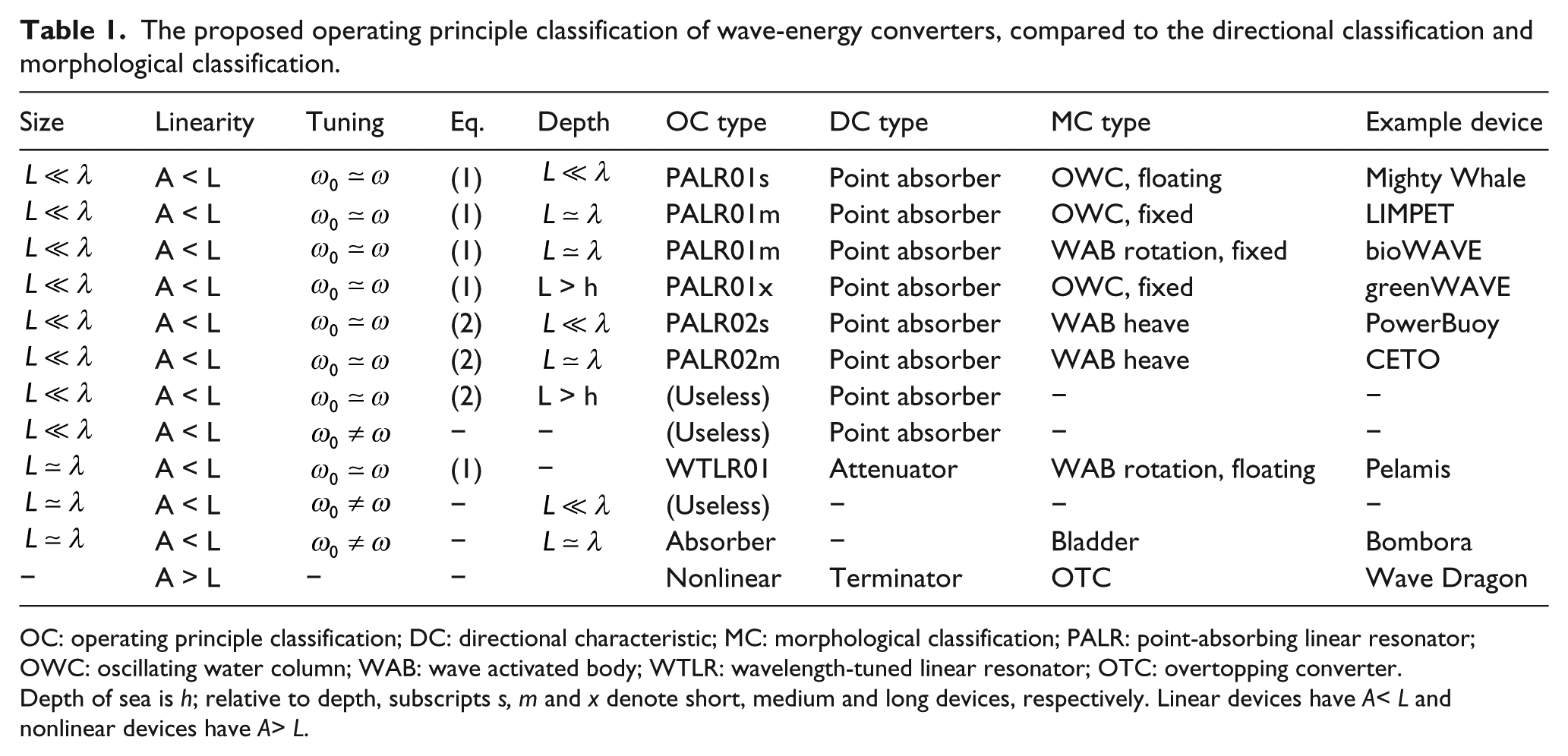
OC: operating principle classification; DC: directional characteristic; MC: morphological classification; PALR: point-absorbing linear resonator; OWC: oscillating water column; WAB: wave activated body; WTLR: wavelength-tuned linear resonator; OTC: overtopping converter.
Depth of sea is h; relative to depth, subscripts s, m and x denote short, medium and long devices, respectively. Linear devices have A< L and nonlinear devices have A> L.
Relevance of WEC classifications to coastal communities
In Table 2, we estimate the relevance of WEC classification systems for the needs of coastal societies. This table is neither comprehensive nor immune to change as technologies develop; it is intended as merely an indication of how rational decision-making might be undertaken. Imagine, for example, that coastal protection is being considered for an Australian coastal community that derives most of its income from tourism in an area of great natural beauty that remains virtually unaltered in appearance by human activity. As will be detailed in section ‘Wave-energy development’, engineering a development that affects the coastal appearance without continually informing all elements of the community can create unforeseen reactions (Torre-Enciso et al., 2010). Moreover, say our example community is on the Southern Ocean where, as noted in section ‘Needs for coastal protection in changing climate scenarios’, winter-time wave heights are projected to increase. Here, for example, the DC is highly relevant. To realistically offer protection, several devices would be needed, and the need for the devices to be visually unobstrusive means it would be important to determine whether they are much smaller than the wavelength (point absorbers). Since reducing or eliminating wave action is important, it is necessary to determine whether they attenuate the waves or completely eliminate them (terminators). The morphological characteristic would not be of high relevance in this example, since the presence of several units close to shore offers some efficiency in their servicing and maintenance. Nonetheless, the MC affects the appearance of the installation, so cannot be neglected in a tourism-intensive local economy. The OC is of medium relevance; nonlinear devices may be the most effective in removing the peaks from storm extremes, whereas linear resonators could remove energy from a large region of wave front. If coastal protection is required for an industrial region without the need to preserve the aesthetic value, both the DC and MC drop in relevance while the OC remains of medium relevance.
Applications of WEC classification systems.
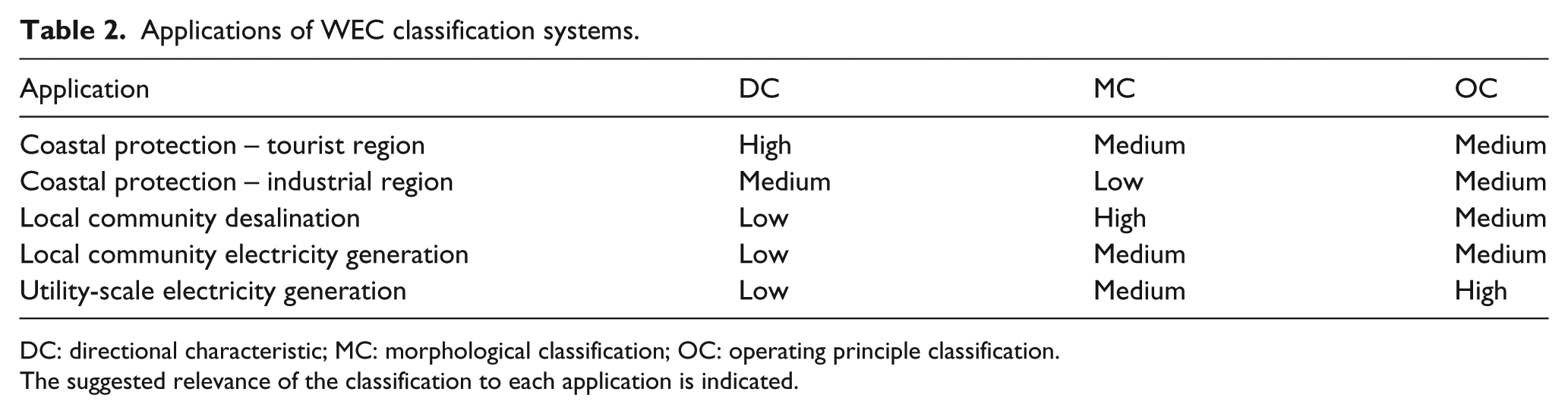
DC: directional characteristic; MC: morphological classification; OC: operating principle classification.
The suggested relevance of the classification to each application is indicated.
Meanwhile, if the local community is a small, remote island that needs a single electricity generator, the effect a single device has on the wave field is probably less relevant than the device morphology. The MC would govern the ease of maintenance and operation; the device may need to be serviced locally, without the economies of scale offered by a large installation. An example where a remote-island installation was initially unsuccessful is given in section ‘Wave-energy development’. However, for desalination, some specific WEC technologies inherently generate high pressures internally, which may be better for a desalination application. The OC would provide a useful differentiator of technologies in the remote-island cases, but not as useful as the MC.
For utility-scale electricity generation, neither the DC nor the MC would be as important as the OC, which would best differentiate the economic efficiency when many units are operating.
Finally, using the most appropriate classification from Table 2, it is possible to compare some WEC technologies from the perspective of integrating them into coastal-community needs, as shown in Table 3. As with Table 2, Table 3 should be considered as merely an illustration of how decision-making might be guided. As technologies change and new applications emerge, Tables 2 and 3 would need to be improved.
Applications of WEC technology types, under the most appropriate classification shown in Table 2.
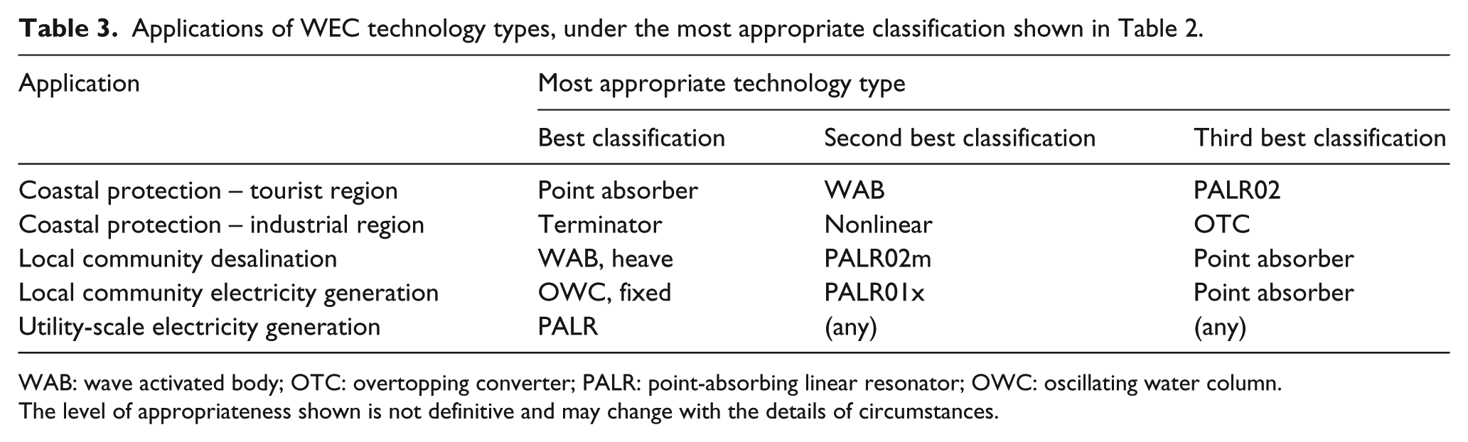
WAB: wave activated body; OTC: overtopping converter; PALR: point-absorbing linear resonator; OWC: oscillating water column.
The level of appropriateness shown is not definitive and may change with the details of circumstances.
Tidal-power systems
Classification of tidal-power systems
In contrast to waves, the tides have the advantage of being unidirectional flows, at least for 6 h, so that the concept of a conventional turbine may be utilised, only requiring that the entire device swivels by 180° when the tide reverses. The fundamental operating principle is the same for all but one class of tidal technologies. Hence, unlike wave power, there is no need to discuss the higher-level concept of which classification system is best. The classification adopted here is thus an MC, which is easiest to comprehend.
Where tidal flow speeds are high, the use of a conventional FT is possible (Lago et al., 2010). However, in most locations worldwide, tidal flow velocities are too low to spin a turbine with reasonable economic efficiency, requiring flow-augmented or DTs, in which cowlings, ducting or converging shrouds increase the flow speed to useful values, by capturing the mass flow over a larger area than that swept by the turbine blades.
The extreme limit of a flow-speed-increasing system is the TB, in which an entire river or bay mouth is blocked by a dam, forcing the entire flow through turbines mounted in the barrage (e.g. Charlier, 2007). This has the huge advantage of capturing all the available tidal energy of the region inland of the barrier, irrespective of the flow speed. It may also facilitate protecting the region inland of the barrier from extreme events. However, it has the disadvantages of potential environmental impacts and of high capital cost with limited prospects for modular scale-up in the number of units.
Kite turbines (KTs) are also proposed for tidal power, in locations where tidal flow speeds are too low. The KT moves at the end of its tether through a figure-of-eight cycle in a vertical plane, similarly to a kite flying in the wind (Olinger and Wang, 2015). The speed during the cycle can be much higher than the current speed, and thus becomes sufficient to turn the turbine. Since the machine is free to move, the torque produced by the turbine must be balanced by a moment produced by the wing, or by a counter-rotating turbine. Sophisticated control systems are necessary to ensure the pattern of motion is appropriate and that the device body does not rotate in response to the torque of the blades. These devices are also proposed for ocean-current power systems (section ‘Ocean-current power systems’).
A further class of technologies able to capture power from low-speed flows utilise the vortex-induced vibration (VIV) concept (see examples in Lago et al., 2010). This is the one tidal-power concept, as mentioned above, that is not a turbine. Here, the shedding of vortices as they pass a bluff body (ranging from a simple cantilevered cylinder to an aerofoil section) causes the body to oscillate at right angles to the flow direction. This oscillating motion can be used to generate power via a crank or similar mechanism. By arranging for the oscillating system to have a stiffness restoring it to its equilibrium position, the system can be arranged to resonate at a particular flow speed, amplifying power extracted from the flow. Similar issues occur to those affecting WECs, as noted in section ‘Two existing classification systems’: the efficient transformation from reciprocating to rotary motion inevitably requires more than one moving part, which may be problematic in the marine environment.
Relevance of tidal-power technology types to coastal communities
Some of the circumstances under which various tidal technology types could be considered for coastal communities are listed in Table 4. It can be seen that there are circumstances when some technologies may be appropriate and others inappropriate. As for Tables 2 and 3, it must be emphasised that the judgements made in Table 4 cannot be definitive, but are merely a guide to rational decision-making on technology types. In the local community category, an isolated island community is contrasted with a community that is close to a bay or lagoon that has a narrow entrance to the ocean.
Applications of tidal-power technology types, under a morphological classification.
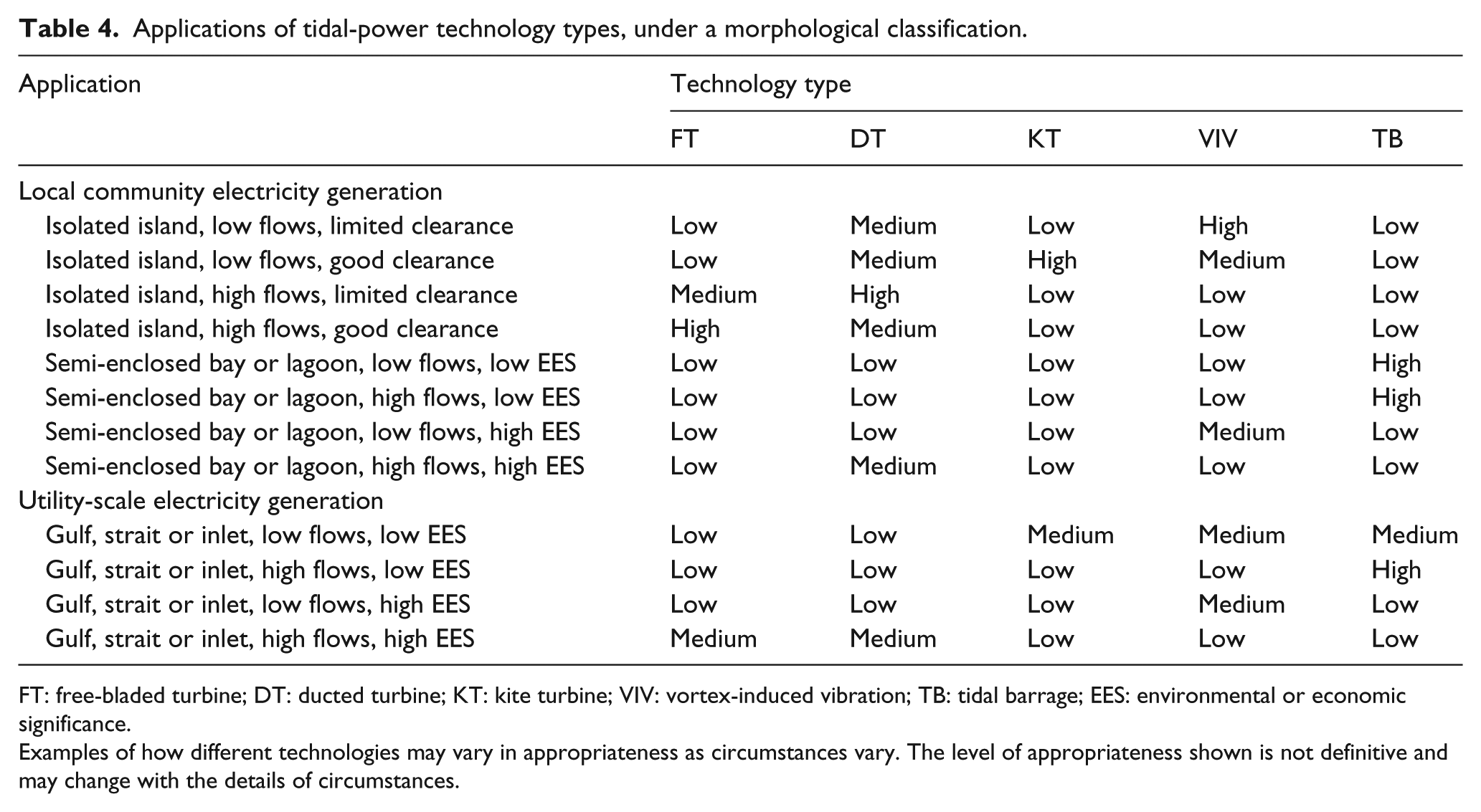
FT: free-bladed turbine; DT: ducted turbine; KT: kite turbine; VIV: vortex-induced vibration; TB: tidal barrage; EES: environmental or economic significance.
Examples of how different technologies may vary in appropriateness as circumstances vary. The level of appropriateness shown is not definitive and may change with the details of circumstances.
In general, narrow channels connecting larger bodies of water are those with significant tidal velocities. It should be noted that the FT may pose a risks to marine life and vessels, so may be unsuited for shallow and narrow channels (zones of limited clearance) in which there may be significant faunal or human traffic. It is in the limited-clearance environment that DTs may be better; the presence of the ducting does not eliminate collisions, but greatly reduces their severity; and an entrance net or mesh is possible, precluding ingress of large fauna, even though entanglement then becomes an issue. It is also in the limited-clearance environment that VIV systems may have some advantage.
Meanwhile, the KT needs room to manoeuvre, implying it is best situated in a large channel with minimal traffic. The complexities of controlling a KT also imply that operations may require human oversight by someone with advanced training and the ability to intervene if behaviour is not optimal. Such control is possible remotely, but a trained local presence is nonetheless indicated, implying that a remote island with a low population may find KT operation problematic.
The TB clearly has the most significant potential environmental impact, where the environmental or economic significance (EES) of the zone of interest refers to both the natural and the economic value of the zone. For example, the EES may be high if the present state of the zone must be maintained to sustain fish populations or the transit of vessels of economic significance, or to sustain a natural ecosystem of special significance. However, as noted in section ‘Classification of tidal-power systems’, the TB offers the benefit of insulating a coastal community against storm surges.
Ocean-current power systems
Ocean-current flows have the advantage of being unidirectional, and therefore the technology concept applicable is the turbine. To understand the advantages and limitations of ocean-current systems, a brief summary of ocean currents in required.
Immense kinetic energy is present in the planet’s great ocean-current gyres, corresponding to a power estimated at 1 TW (Wunsch, 1998). The gyres are driven by the Hadley cells that are the most fundamental component of the atmospheric circulation (Gill, 1982); these winds (which also create the ocean swell as noted in section ‘Wave energy’) are, in turn, an inevitable consequence of solar heating of the Earth (Figure 1). The presence of continents affects the strength and size of the gyres. In particular, the Coriolis force due to the Earth’s rotation reaches a balance with the stress due to water movement at the continental shelf, to create a phenomenon known as westward intensification Gill (1982). This means that the ocean gyre is not a spatially uniform orbit of water around the ocean basin. Rather, the flow is concentrated into an intense current along the western boundary of the ocean basin that brings warm water from the subtropics to the temperate latitudes. The most famous of these western boundary currents is the Gulf Stream on the western boundary of the North Atlantic, with an estimated mass transport of about 32 × 106 m3 s−1 (Bryden et al., 2005). Other western boundary currents, noting their mean estimated mass transports reported in Bryden et al. (2005), are the Brazil Current (South Atlantic; 16 × 106 m3 s−1), the Kuroshio (North Pacific; 32 × 106 m3 s−1), the East Australia Current (South Pacific; 22 × 106 m3 s−1) and the Agulhas Current (Indian Ocean; 70 × 106 m3 s−1).
There are many other large-scale ocean-current systems, such as the cold currents found on the eastern side of ocean basins, but they generally offer weaker flow speeds than western boundary currents. Even in the western boundary currents, the actual flow speeds are modest, ranging from several tens of centimetres per second to about 1–2 m s−1. This raises the same issue with the majority of the world’s tidal flows: speeds are mostly too low to turn a turbine of economic size.
From the perspective of coastal communities, a further issue is that the corresponding kinetic energy is distributed over a wide area, so that the power deliverable to any given point on the coast may be modest without a large capital investment in undersea cabling. Nonetheless, for a coast with a western boundary current immediately offshore, ocean-current power may be an option. Examples include the coasts of Florida, South Carolina and North Carolina in the United States; Brazil south of 10° S; the Japanese archipelago south of Tokyo and Taiwan; Southern Queensland and northern New South Wales in Australia and southern Mozambique and the south-eastern coast of South Africa.
Since ocean-current power systems are mostly turbines in concept, they may be divided into two classes: fixed FTs, as with tidal power, that are mounted or tethered so that their movement is minimal, and KTs that must move to generate economically efficient power. It is also possible that VIV devices, mentioned in section ‘Classification of tidal-power systems’, may be employed. Fixed FTs have been designed which could operate in the high-speed parts of Kuroshio off Japan and Taiwan; these concepts are tethered to the bottom, and float below the surface at the depth where speeds are greatest (IHI Corporation, 2014). For current speeds that are too low, KTs (noted in section ‘Classification of tidal-power systems’) have been proposed and trialled. This class of machine was thought most appropriate for the Agulhas Current (Meyer and Niekerk, 2016).
Western boundary currents can meander, changing their direction over the course of days of weeks, and can break into eddies. Thus, the currents can vary in strength and direction. Therefore, similarly to wind turbines, an ability to adjust the axis of the turbine to point into the current would be beneficial.
We do not introduce a decision guide for ocean-current power as for wave and tidal power, because the choices at the present immature state of worldwide developments are limited. For high-speed flows, FTs or DTs may be useful, as will be discussed in section ‘Kinetic energy from ocean currents’; for low-speed flows, the newer and more complex KT or VIV concepts may be considered.
Ocean-thermal energy conversion systems
Ocean-thermal energy conversion (OTEC) utilises the difference in temperature between warm surface water and the cold deep water (Vega, 2002), which are due to the Sun’s heat (Figure 1). The cold water is pumped to the surface, which requires some energy input, and the difference in temperatures is then used to drive a heat engine. Clearly, the energy obtained from the temperature difference must exceed the energy needed to pump the cold water to the surface. A temperature difference of 20°C or above is required, implying that OTEC is only likely to be possible in the tropics (Heydt, 1993); at depths around 1000 m or greater, the world ocean temperature is a few degrees Celsius, and it is only in the tropics that surface temperatures exceed 20°C. Furthermore, the distance over which the water must be pumped is important; ideally, the OTEC system would be in deep, tropical seas so that a long horizontal pipe, with its attendant frictional losses, need not be used.
There are two classes of OTEC: closed-cycle (CC) and open-cycle (OC) (Finney, 2008; Jalihal, 2005; Vega, 2002). In CC-OTEC, a working fluid with a low boiling point is evaporated in a heat exchanger warmed by the surface water. The vapour expands, doing work by driving a turbine or similar heat engine connected to an electric generator. The vapour is then condensed back into liquid in a second heat exchanger cooled by the deep water and returned to the start of the circuit. The use of a contained low-boiling-point working fluid is the same concept underlying the vast majority of CC heat pumps in industry or the home, such as refrigerators and air-conditioning systems. However, such working fluids are usually substances that should not be released to the environment, and to generate economically significant amounts of power, large volumes of working fluid would be required. Thus, leaks must be prevented. The working fluid most often cited is ammonia (Finney, 2008).
In OC-OTEC, the working fluid is the seawater itself, avoiding potential pollution issues if a leak were to occur. A vacuum pump is driven, as is the pump bringing up the cold deep water, by the power generated. The vacuum causes the warm surface water to flash off into vapour; this steam then expands, doing work by driving a turbine. As in CC-OTEC, the vapour is then condensed back into liquid in a second heat exchanger cooled by the deep water, raising its pressure back to atmospheric and thus permitting its removal from the vacuum system. An obvious advantage is that the condensed water is completely desalinated and available for human consumption, agriculture and so on. It is also possible to use an OTEC system purely to desalinate water; this has been demonstrated for Indian islands (e.g. Kathiroli and Jalihal, 2008; see section ‘OTEC’). However, the OC-OTEC concept has more complications than CC-OTEC. The concentrated salt solution – and any biological residues – that is left behind during the flashing-off process must be removed. Furthermore, during the flashing-off process, atmospheric gases dissolved in the surface seawater are liberated, but do not re-dissolve on condensation, and must be eliminated.
Integration of wave and offshore wind energy
We do not detail one form of MRE in this review, owing to its comparatively well-established nature: offshore wind energy. In some locations, such as the southern coastline of Australia, great distances of windy coastline with very low populations make onshore wind power much less expensive than offshore wind power. Moreover, like onshore wind power, offshore installations carry attendant issues of aesthetic impact, particularly in regions where there is a high dependence on income from tourism attracted to a pristine coastline. In India, however, offshore wind has been carefully assessed (Gomathinayagam, 2016).
Integration of offshore wind turbines is possible with all forms of MRE excepting ocean-current energy, which is likely to involve installations well below the surface. The integration of offshore wind with WECs in particular was recently reviewed by Pérez-Collazo et al. (2015), who use the MC to classify WECs. Particular benefits include the ability of WECs to shield wind turbines from wave action, and, in the case of floating wind turbines, to damp movement of the turbine tower. Furthermore, shared electrical infrastructure would reduce capital costs.
Experience from MRE developments in coastal communities
India has a very long coastline of about 7517 km, possessing all forms of MRE (waves, tidal currents, offshore wind and thermal gradients), lacking only an intense western boundary current due to an ocean gyre. Historical developments in India are summarised in Figure 2. The energy potential of Indian seas demands exploration and harnessing to meet the energy requirements of a power-starved nation. Correspondingly, the National Institute of Ocean Technology (NIOT) in India has the mandate from the Government of India to develop MRE sources along the Indian coastline. The institute has been working on wave energy and hydrokinetic devices for marine currents. NIOT also has worked on offshore-platform-mounted OTEC as detailed in section ‘OTEC’. Although several difficulties were faced in the OTEC project, the learning was utilised in its spin off product – desalinated water. NIOT has developed great expertise in low-temperature thermal desalination using ocean temperature gradients.
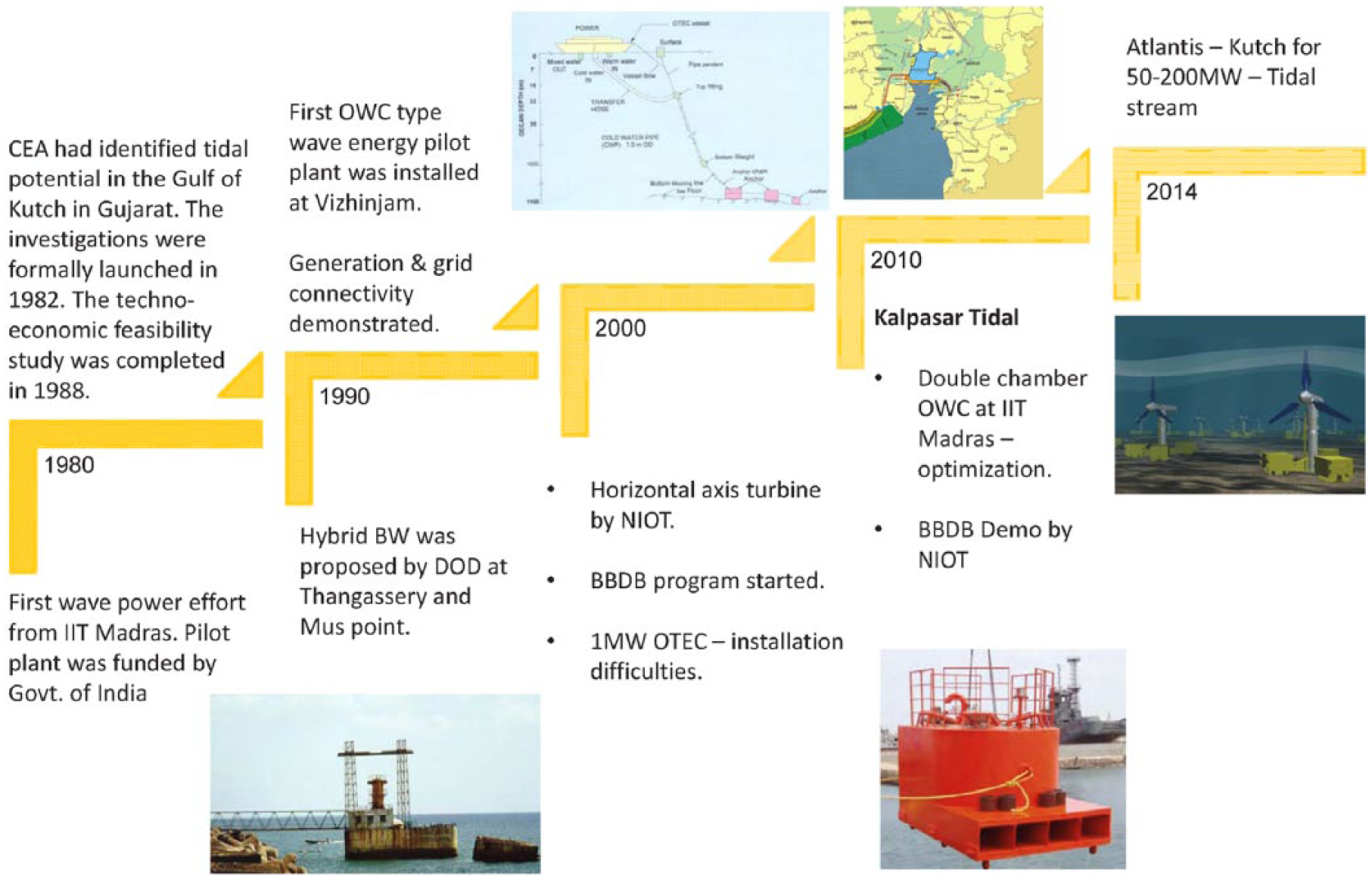
Historical efforts in India on MRE.
Meanwhile, as explained below, although Australian MRE developers have carefully taken into consideration the needs of coastal communities, the tailoring of developments to the needs of coastal communities has not been their primary objective to date. In this section of this review, we summarise the experience of MRE developments relevant to coastal communities, comparing and contrasting India and Australia in particular. We neglect only tidal power; since tidal power has been trialled in Australia but not explicitly for coastal-community needs, we refer to the Australian tidal-power review in section ‘Resource assessment techniques for the major MRE classes’ of Manasseh et al. (2017) and to references therein.
Wave-energy development
The first wave-energy plant in India was established in Vizhinjam, Kerala, India, by the Ocean Engineering Centre of the Indian Institute of Technology Madras. This plant was based on a fixed OWC principle (Sundar et al., 2010). As described in section ‘Two existing classification systems’ (Table 1), this machine would be of type PALR01m under the operational classification and type OWC-fixed under the MC; according to Table 2, these two classifications are appropriate for the application ‘Local community electricity generation’. According to Table 3, the fixed OWC was indeed the best choice for this application, when the most appropriate classification is applied. The plant was further developed and several power modules were studied. Several turbines and generators were tested in this plant. The first impulse turbine was implemented successfully in lieu of the popular Wells turbine. This turbine generated power successfully, which was used to run a reverse osmosis–based desalination plant for the first time ever. The fresh water generated was supplied to the local fishing community and was very much appreciated. The plant was eventually decommissioned since water generation was not the mandate of the NIOT. Subsequently, OWC-based floating WECs were brought into focus for development, and a floating WEC – a backward-bent-duct buoy – has been developed and tested off the Chennai coast. A lot of effort was expended to achieve correct matching between the turbine and the OWC. Now, a wave energy–powered navigational buoy has been designed. It will be shortly fabricated and tested off Chennai. Efforts towards scaling-up of floating wave-energy devices have been initiated.
Small off-grid floating wave-powered devices would be very useful for Indian coastal communities. All-weather devices in the range of a few kilowatts will be the next stage of development.
Australian WEC developments are detailed in Manasseh et al. (2017), section 2.2.2. Of the four OWC machines constructed, one was floating and the others bottom-mounted. Two were grid-connected, and the promotional material of the developing company suggested that utility-scale electricity generation was the objective, although desalination was contemplated for one machine. For utility-scale electricity generation, Tables 2 and 3 show that any PALR could be appropriate, so the choice of the OWC was reasonable, as might the choice of any other point absorber.
For one OWC, the Oceanlinx greenWAVE, its proposed sitting in a small coastal town, Port Macdonnell, South Australia, required extensive local community consultation. The local community relies on fishing, particularly for rock lobsters, and was assured that the bottom-mounted OWC would not inhibit their operations. Fishing boats were to be permitted to dock with the structure, and the company’s website claimed the machine may encourage marine life by forming an artificial reef. As detailed in Manasseh et al. (2017), this deployment was never realised; the just-constructed machine was shipwrecked during its tow to location.
The most successful Australian wave-power trial to date, judged by scale and longevity, was the Carnegie Wave Energy (CWE) CETO5 trial of an array of three heaving-buoy machines (Operational Classification PALR02m in Table 1) over the year of 2015 (detailed in Manasseh et al., 2017). It was grid-connected. The connection was to a navy base that was its immediate neighbour, rather than a coastal community, with the security-led application of providing the base with alternative power if the base were to lose its own grid connection. The Biopower Systems WEC (PALR01m), installed in December 2015 at Port Fairy, Victoria, was also designed for grid connection, and like the Oceanlinx proposal for Port Macdonnell, extensive consultation with the local community occurred. Both devices, being PALRs, were appropriate for utility-scale electricity generation according to Tables 2 and 3.
However, the presence of grid connection means these were not explicitly intended to meet coastal-community needs. In an interesting application, CWE formed an agreement with Electricité de France to supply Réunion Island in the Indian Ocean, and a trial occurred in 2014. This was a clear example of local community electricity generation, for which, according to Table 3, a fixed OWC (as at Vizhinjam, India) may have been better. This CWE machine was destroyed in a cyclone.
Protection of coasts from wave action is of increasing interest, as noted in section ‘Needs for coastal protection in changing climate scenarios’. Structures based on the OWC concept (Arena et al., 2013) have been designed for harbour protection and are clearly relevant to coastal communities that may be at risk from inundation. The OWC WEC plant at Mutriku, Spain, was intended to be integrated into a concrete breakwater, and thus also satisfied the local community need (Torre-Enciso et al., 2010). However, as noted by Torre-Enciso et al. (2010), there was an interesting reversal of the usual political discourse associated with renewable energy developments. Environmentalist groups had been opposed to the breakwater prior to the incorporation of WECs, and when WECs were integrated into the design, this was dismissed as an attempt to foil their opposition. It is possible that classification of the application as ‘Coastal protection – tourist region’ in Tables 2 and 3 captures the issue that the structure was felt to be intrusive and environmentally inappropriate. If so, Tables 2 and 3 indicate that while a point absorber of any type is appropriate, having a submerged WAB rather than an OWC may have been better.
Kinetic energy from ocean currents
As detailed in section ‘Ocean-current power systems’, energy can be extracted from ocean currents using submerged turbines that capture energy from hydrodynamic lift and drag forces. In India, NIOT is developing technologies related to such hydrokinetic turbines. During the course of development, the turbine designs have been analysed and optimised using computational fluid dynamical principles. Then the scaled-down turbines have been tested in laboratories and a seawater channel in north Chennai, Tamil Nadu, India. As a result of these extensive studies, NIOT recently carried out successful open sea trials in the Andaman and Nicobar Islands of a small hydrokinetic turbine that converts kinetic energy in ocean currents into electricity. Now the design of larger-capacity turbines is in progress. The challenge of developing ocean-current power in Indian coastal waters is due to the low current velocities. Designing self-starting turbines at low velocities with low speed alternators is complex and is required for the Indian climate. The first success on a small turbine tested in the open Andaman Sea paves the way for larger off-grid modules for the remote coastal locations and islands of India.
In Australia, there have been no proposals to the best of our knowledge to develop ocean-current power, despite an excellent resource in the East Australia Current (section ‘Ocean-current power systems’, and Manasseh et al., 2017). The relevant parts of the Australian eastern seaboard are all connected to the national electricity grid and do not feature any island communities independent of the grid. Thus, ocean-current power in Australia is most probably to be considered for utility-scale operation.
OTEC
The third type of ocean energy dealt with at NIOT is the energy from thermal gradients or OTEC, which was outlined in section ‘Ocean-thermal energy conversion systems’. Being close to the equator, the sea surface is always fairly warm in Indian waters. The ocean’s temperature varies with depth. The temperature profiles indicate that the temperature at around 1000 m water depth could be as low as 4°C–6°C. This difference in temperature between the sea surface and at a deeper depth was utilised to harness energy by running a Rankine cycle–based power plant.
Although the technological challenges are many and demonstration of OTEC for larger power ratings is yet to be successful anywhere in the world, it is important to harness this form of energy due to the large coastline and tropical water temperatures prevailing in Indian waters. In coastal communities that are not grid-connected, such as islands, fossil fuels’ reliance is problematic. Hence, NIOT attempted a barge-based 1 MW OTEC plant and sub-system-level testing was carried out. The plant could not be made operational due to challenges in connection of the 1-km-long cold water pipe to the main barge and unavailability of marine infrastructure. To get more experience, it was decided to try desalination at lower depths and NIOT successfully demonstrated a 1 million litre per day low-temperature thermal desalination plant on the same barge in deep waters, using the OC-OTEC principle. NIOT has already commissioned low-temperature thermal desalination plants of 100,000 L per day capacity at Kavaratti, Minicoy and Agatti Islands of the Indian Union Territory of Lakshadweep (Kathiroli and Jalihal, 2008). These plants have improved the health of the islanders and helped capacity building at NIOT. Now it is proposed to run the desalination cycle using the OTEC power to achieve low-cost water of high quality. To this end, NIOT is readying a laboratory-scale CC OTEC unit along with the desalination cycle for further research and development
OTEC-powered desalination shows tremendous prospects for the long Indian coastline and for islands in Lakshadweep and Andaman. NIOT has now developed expertise in the process design, cold water pipe deployment and offshore engineering. Scaling-up efforts are now in progress. These developments illustrate, perhaps better than any others worldwide, the successful integration of MRE with the needs of coastal communities.
As noted in Manasseh et al. (2017), the northern seas of Australia are where OTEC may be viable in principle. However, the western flank of the continent has a very wide and shallow continental shelf, making OTEC impractical: there is no ready access to deep cold water. This geography is also responsible for very large tidal ranges, as noted above. If OTEC is to be viable for a local community in Australia, it would need to be where the edge of the continental shelf is within reach of a community and the waters are tropical. The coast of far north Queensland between Innisfail and Cooktown is where the tropical continental shelf is narrowest; even here the coast is roughly 100 km from the continental shelf edge, and there are no significant island communities near the shelf edge. In the Torres Strait, there are many island communities completely dependent on fossil fuels for energy. Unfortunately, the Torres Strait is very shallow, making OTEC problematic; conversely, the Torres Strait has some strong local tidal flows.
Engineering and economic efficiencies
The first question usually asked of a new energy technology is ‘what is its efficiency?’ The engineering efficiency is usually the ratio of the useful power delivered by the system to the total power available. However, in a renewable energy context, it can be difficult to draw a boundary around the system that defines the total power available, and hence the denominator of the ratio is uncertain. For example, in a tidal-power context, it is only the TB system where there is a definite boundary, since all the water behind the barrier has been trapped; in all other tidal systems, it is unclear where the boundary is. In an OTEC or ocean-current system, it is also unclear. Engineering-type efficiencies can be defined for turbines in open flows; for example, the Betz limit of 16/27 (59.3%) applies equally to free turbines in either water flows or in wind. However, this has little practical meaning beyond expressing how close an individual turbine design is to ideal. Wave-power systems can quote their engineering efficiency relative to the power per metre of the incoming wave crest. However, since resonating WECs can trap wave energy over a width of wave crest larger than their physical size, an efficiency greater than 100% could be calculated, which is nonsensical. Thus, the capture width of WECs is more commonly quoted: the width of the wave crest in metres over which 100% of the power is captured. However, for any resonating device extracting power from an external source, the efficiency of mechanical conversion can be calculated as the ratio of the useful power delivered to the power extracted from the ocean, irrespective of how that power has been extracted. This ignores the issue of defining a boundary enclosing the ‘total power available’. It is easy to show this mechanical-step efficiency can never be more than 50% (e.g. Beeby et al., 2006; Falcão, 2010) provided the behaviour remains linear, and since most WECs are resonators, this sets an upper bound on the engineering efficiencies of most WECs.
A more pertinent question concerns the economic efficiency, usually expressed as the LCOE. Ultimately, this is the number that matters and includes the cost of repaying the capital needed to construct the facility, the cost to operate and maintain it and the cost to transmit the power to the grid. The LCOE for wave and tidal power in 2030 was analysed in the Australian context by Behrens et al. (2012) and is summarised in Table 5. Behrens et al. (2012) assumed a capacity factor of 0.4, that is, they assumed that owing to natural variations, each technology would on average deliver 40% of the maximum it was capable of delivering. Although the numbers would differ in regions with different wage and material costs, the relative cost of the various types of MRE may be similar elsewhere in the world. Vega (2014) undertook calculations for wave and OTEC power, also shown in Table 5, under differing assumptions to Behrens et al. (2012). Vega (2014) produced estimates for ‘future’ wave-power LCOE at 40% capacity factor that were somewhat higher those of Behrens et al. (2012) ‘2030’ wave-power LCOE. Meanwhile, Behrens et al. (2012) estimated the cost of wind power to be AUD 60–170 per MW h, and a more recent estimate of present-day wind energy was AUD 80–90 per MW h (McConnell, 2015).
Estimated future levelised costs of electricity of various forms of marine renewable energy in Australia and Asia.
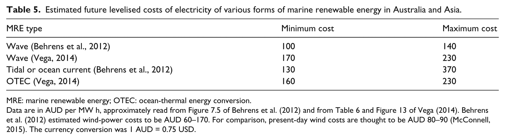
MRE: marine renewable energy; OTEC: ocean-thermal energy conversion.
Data are in AUD per MW h, approximately read from Figure 7.5 of Behrens et al. (2012) and from Table 6 and Figure 13 of Vega (2014). Behrens et al. (2012) estimated wind-power costs to be AUD 60–170. For comparison, present-day wind costs are thought to be AUD 80–90 (McConnell, 2015). The currency conversion was 1 AUD = 0.75 USD.
Discussion
Several forms of MRE are covered above, encompassing wave, tidal, ocean-current and ocean-thermal energy. A fifth form of MRE, salinity-gradient energy conversion, is detailed elsewhere (Kempener and Neumann, 2014). The challenges facing India in harnessing MREs are the low intensities of waves and low tidal and ocean-current speeds. Implementation of sustainable offshore platform-mounted all-weather OTEC plants is an ongoing ambition based on solid results so far. The MRE efforts in India over the past few decades are comprehensively captured in Figure 2. There has not been focussed research and development in this area. Furthermore, developments show a lack of top–down planning in terms of development of marine renewable technologies. Nonetheless, in India there has been research and development organised and co-coordinated by government agencies and universities. Servicing the energy- and water-security needs of Indian coastal communities has been a high priority for India.
In contrast, Australia has favoured a laissez-faire approach where entrepreneurs take the lead. Australia has all classes of MRE: wave, tidal currents, ocean currents due to gyres and ocean-thermal gradients. Also in contrast to India, Australian developments have been initiated by private entrepreneurs funded initially by venture capital, with major government support of these private developers occurring only in the last decade (Manasseh et al., 2017). There have been at least eight independent wave-power developers, two major tidal-power developers and several smaller tidal developers. The drivers have been very different: the nation is already rich in energy, albeit dominated by fossil fuel sources, and entrepreneurs have sought to utilise the nation’s seas as an ideal test-bed for patented technologies, enabling commercialisation worldwide. This plan has had some success, particularly with the relatively conventional technologies of tidal power as noted in Manasseh et al. (2017). However, as the nation decarbonises its energy supplies, the energy needs of Australian communities – as well as their coastal-protection needs – are increasingly debated, and attention is turning to renewable supplies of local energy rather than testing technologies intended ultimately for export.
An impressive – and confusing – variety of technologies has been deployed in the sea with the aim of extracting renewable energy. From the perspective of coastal communities, decision-making should commence with an identification of the needs, which may be
Protection from waves or storm-surge inundation
An electricity supply independent of fossil fuel supplies
Fresh water
A tourist attraction. It is worth noting that at least one MRE development (Tidal Lagoon Swansea Bay, 2014) intends to realise the potential of the development in attracting tourists.
Having picked its first priority, the community can then proceed to a resource assessment to determine how much energy is realistically present. In the references cited in section ‘Resource assessment techniques for the major MRE classes’, techniques are presented for assessing the major classes of MRE: wave and tidal power. For ocean-current power, proximity to a steady, major current system is required, recalling that these are currents due to oceanic wind-driven circulation, which should not be confused with tides. Unlike tides, ocean currents do not reverse periodically. For OTEC, the sea-surface temperatures should exceed 20°C and the community should be located close to the edge of the continental shelf, so that depths of several hundred metres are within reach.
Communities should then work through the different sub-classes of the most appropriate form of MRE for their location as described in section ‘Resource assessment techniques for the major MRE classes’. Where technical calculations are needed, an appropriate and ideally impartial consultant can be engaged, who could elaborate the tables in section ‘Classification of technologies’ to suit the community’s needs. The community should then consider options of integrating a second or third need from the list above into the development. The pros and cons of the development can be discussed at a public forum. Finally, a tender can be written for the development. This approach has the community making the decision, but that may not be appropriate for nations or regions with a history and expectation of central control. Even in this case, a decision-making process based on community needs is the same. Finally, the LCOE should be considered. It has been noted several times that if WECs are used to protect the coast from waves, there could be a significant reduction in LCOE, since some capital may be sourced from the coastal-protection imperative (Falcão, 2010; Manasseh et al., 2017; Torre-Enciso et al., 2009). Clearly, the sale of electricity could alternatively defray the cost of any borrowings required for coastal-protection infrastructure. An illustration of a decision-making process is given in Table 6.
Decision matrix for coastal communities considering marine renewable energy.
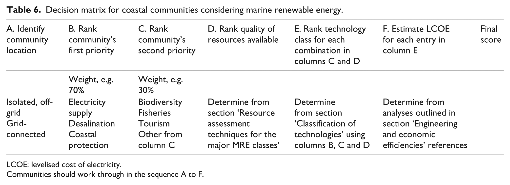
LCOE: levelised cost of electricity.
Communities should work through in the sequence A to F.
Where MRE installations have been successful in either India or Australia, it is clear that the technology classification has suited the application. Tropical island communities in need of fresh water and near deep water are an obviously beneficiary of OTEC-OC. Concrete, shore-based WECs have suited the local community electricity generation and coastal-protection applications where the environmental or aesthetic impact of the development has not been a major concern. These are by far the most robust, and easy to operate, upgrade and maintain. However, the classification also shows that where there is significant aesthetic impact, irrespective of the actual environmental impact, shore-based devices or other structures that are surface-piercing may be less appropriate than subsurface machines.
Conclusion
MRE exploits a variety of forms of energy, including the heat in the atmosphere driving winds, waves and currents, the heat in the oceans and the gravitational potential in the tides. The disparate forms of MRE share a common practical element: difficulties of deploying, maintaining and operating the technologies in the ocean environment. Mishaps have made investors wary. However, a lack of clarity on the differences between the classes of MRE and the absence of a unified guide to where and when each class and subclass might be appropriate is the most serious inhibitor of investment.
The variety of MRE options and the lack of clarity on their operating principles are particularly problematic for coastal communities. They stand to gain the most from renewable energy technologies exploiting resources on their doorstep – resources that could forestall some of the consequences of climate change such as inundation. Furthermore, local MRE developments could provide valuable local employment and training opportunities. However, coastal communities may not possess the expertise to make those assessments, relying instead on government agencies that may not be well resourced, or on consultations with technology developers who have an understandable vested interest. Moreover, recent experience suggests that socio-economic and political factors at the local community level are very important and these are best articulated by the community itself.
A description and classification of the major types of MRE has been presented. A clear understanding of the different underlying principles of each technology class suggests the need for a comprehensive classification system. While the classification presented here is neither complete nor definitive, it is a framework which can assimilate future experience. This classification has been illustrated with applications to coastal communities in India and Australia.
There is a clear benefit in combining MRE technologies with coastal-protection infrastructure. The combination of two very different aims, insurance against damage from inundation and generation of renewably-sourced electricity, implies that significant cost savings may be achieved. Power generation can utilise coastal-protection infrastructure that is planned or due for renovation, significantly reducing the LCOE. Other uses such as water desalination may also benefit. Likewise, some of the capital required for coastal-protection infrastructure may be repaid by revenue from the sale of electricity or fresh water. Co-locating different and complimentary forms of MRE, such as offshore wind turbines and WECs, may offer additional benefits in the form of shared electricity transmission cabling and protection of floating wind-turbine platforms from wave action.
It is hoped that this article will assist coastal communities in taking the lead in assuring their energy and physical security. Without waiting passively for government agencies or private developers to investigate their location, coastal communities should be able to research and tender for appropriate MRE developments.
Footnotes
Funding
R.M. is grateful for the support of the Australian Renewable Energy Agency, via grant ERP A00575.