
Abstract
High-temperature gas-cooled reactor is a kind of advanced nuclear reactor in which the core is packed with spherical fuel elements. In high-temperature gas-cooled reactors, the operating temperature is higher than that in ordinary light water reactors. In an attempt to analyze the flow pattern and heat transfer situation to provide reference for the safe operation of the pebble bed reactors, a segment of simplified high-temperature gas-cooled reactor core is simulated with computational fluid dynamics method. Four kinds of arrangement, including simple cubic, body-centered cubic, face-centered cubic, and a combination structure of body-centered cubic and face-centered cubic, are studied, respectively. Based on the simulation results, higher heat transfer capability and lower pebble temperature are obtained in the case with the most compact arrangement. The drag coefficient (Cd) for four arrangements with different inlet Reynolds number (Re) is obtained and relationship between Re and Cd is analyzed. In addition, a simulation with a broken fuel element in the body-centered cubic fluid domain has been performed. The results show that the presence of broken fuel may result in uneven flow, which will change the heat transfer condition. So it is better to avoid broken fuel element in a high-temperature gas-cooled reactor.
Keywords
Introduction
High-temperature gas-cooled (HTGR) reactor is widely recognized as a kind of advanced reactor system with higher safety property. In HTGR, the fuel assemblies are packed with spherical nuclear fuel pellets. These pebbles are randomly packed in the core. Helium (He) is flown through the gaps between these pebbles. If we want a higher efficiency, we must increase the temperature, which means the higher probabilities for fuel kernel failure and higher feasibility for fission product to release. The fuel elements for HTGR is tristructural-isotropic (TRISO) fuel, which is considered to be safe under 1600℃. 1 A well understanding of heat transfer flow and pressure drop through a pebble bed core is of utmost importance during the design of HTGR. However, due to the complexity of the pebble structure geometry and the enormous number of fuel elements, it is almost impossible to simulate the whole reactor core using realistic approach. Wu et al. 2 have studied the advantages and disadvantages of both realistic approach and porous approach with computational fluid dynamics (CFD) methodology. The realistic approach can get more detailed and localized characteristics in the fluid and solid fuel regions. Li et al. 3 focused on size of pebbles using k − ɛ turbulent model. The velocity and temperature distributions were obtained and analyzed in the different fuel diameters (e.g. 3 and 6 mm). They discussed the effects of the diameters on the thermal-hydraulic characteristics. Lee et al. 4 carried out a sensitivity analysis for the gap size and found flow regimes and the relevant flow-induced local heat transfer could be fully influenced by the interpebble region modeling. Ferng and Lin 5 performed two kinds of contact modeling between adjacent pebbles, namely point contact and area contact, then compared their results with the famous KTA correlations. Ferng and Lin 6 also studied the arrangement of pebbles, including body-centered cubic (BCC) and face-centered cubic (FCC) arrangement.
Based on the outstanding work carried out by Ferng and Lin, 6 we adopt the numerical methods to simulate more arrangements of pebbles. In the real pebble reactor, the fuel elements are arranged randomly. It is considered as a combination of different structured arrangements, including simple cubic (SC), BCC, FCC, and other kinds of arrangements. We simulated four types of the arrangements, including SC, BCC, FCC, and a combination structure of BCC and FCC (BFCC). Then we observed some flow patterns and velocities of the fluid domain or in some selected planes. Furthermore, the drag coefficient Cd with different inlet velocities and coolant physical properties is also reported in this article. To investigate the effect of broken fuel pebbles, we simulated five half fuel pellets placed in different directions instead of the impact fuel pellets in a BCC arrangement fueled domain. We will also introduce the numerical treatment in CFD and describe the boundary conditions and mesh model. The simulation results and some discussions will be presented too. Finally, some conclusions will be summarized.
Model descriptions
Governing equations
The He gas is flowing through a segment of pebble-packed reactor core and transfer heat with the sphere fuel elements. In this kind of flow and heat transfer process, the continuity, momentum, and energy equation always need to be solved. When it comes to radiation, we can simply ignore it because of the transparency of the coolant and the small temperature difference between neighboring fuel elements as shown in Sobes et al.’s
7
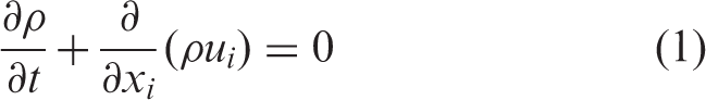
work. The following set of equations is the governing equations solved by FLUENT 15.0 in this process. Continuity equation is as follows
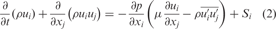
Momentum equation
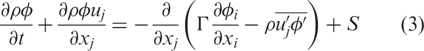
Transport equation
Turbulence model
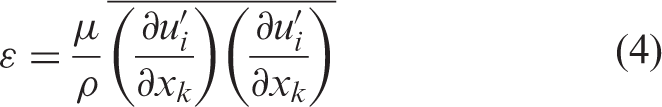
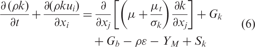
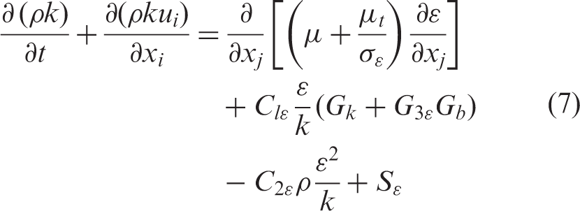
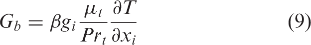
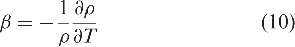
We used k − ɛ model to solve the above equations. Transport equations of k and ɛ need to be introduced. k is turbulent energy and ɛ is turbulent dissipation rate, which is defined as
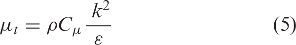
The turbulent viscosity μt can be described with k and ɛ as
The transport equations of k and ɛ are
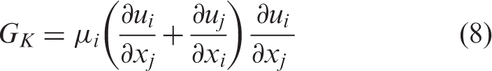
Some useful parameters in the equations are given as follows

Geometry and mesh models
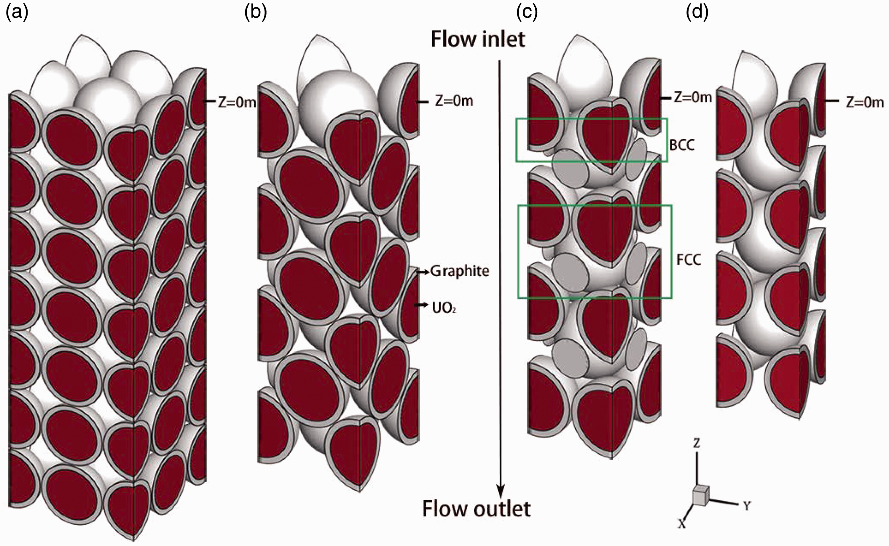
Figure 1 shows the schematics of geometry and mesh models of FCC arrangement of simulation domain. The BCC, SC, and the combined one are similar to this. Figure 1(a) shows a three-dimensional (3D) view of the FCC fuel pebbles. It consists of seven layers of pebbles. Each TRISO fuel element is constructed by two layers. The inner red region represents the UO2 fuel kernel, which consists of a constant heat source as fission power. The outer yellow region represents graphite clad. Energy source is set as zero. Figure 1(b) shows two adjacent pebbles which have an artificial spacing.
8
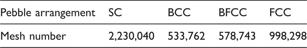
The artificial spacing is introduced with consideration of mesh quality and computing time. We can obtain some mesh details from Figure 1(a), the mesh is unstructured and an inflation layer is applied between gas and cladding, and cladding and fuel, in order to get more accurate results. The mesh numbers are shown in Table 1. The mesh independent calculation was performed with a refinement factor of 1.2 with BCC arrangement and the difference between max temperature is less than 3%.
The schematics of geometry and mesh models of FCC arrangement. Typical mesh number for different pebble arrangements. BCC: body-centered cubic; BFCC: combination structure of BCC and FCC; FCC: face-centered cubic; SC: simple cubic.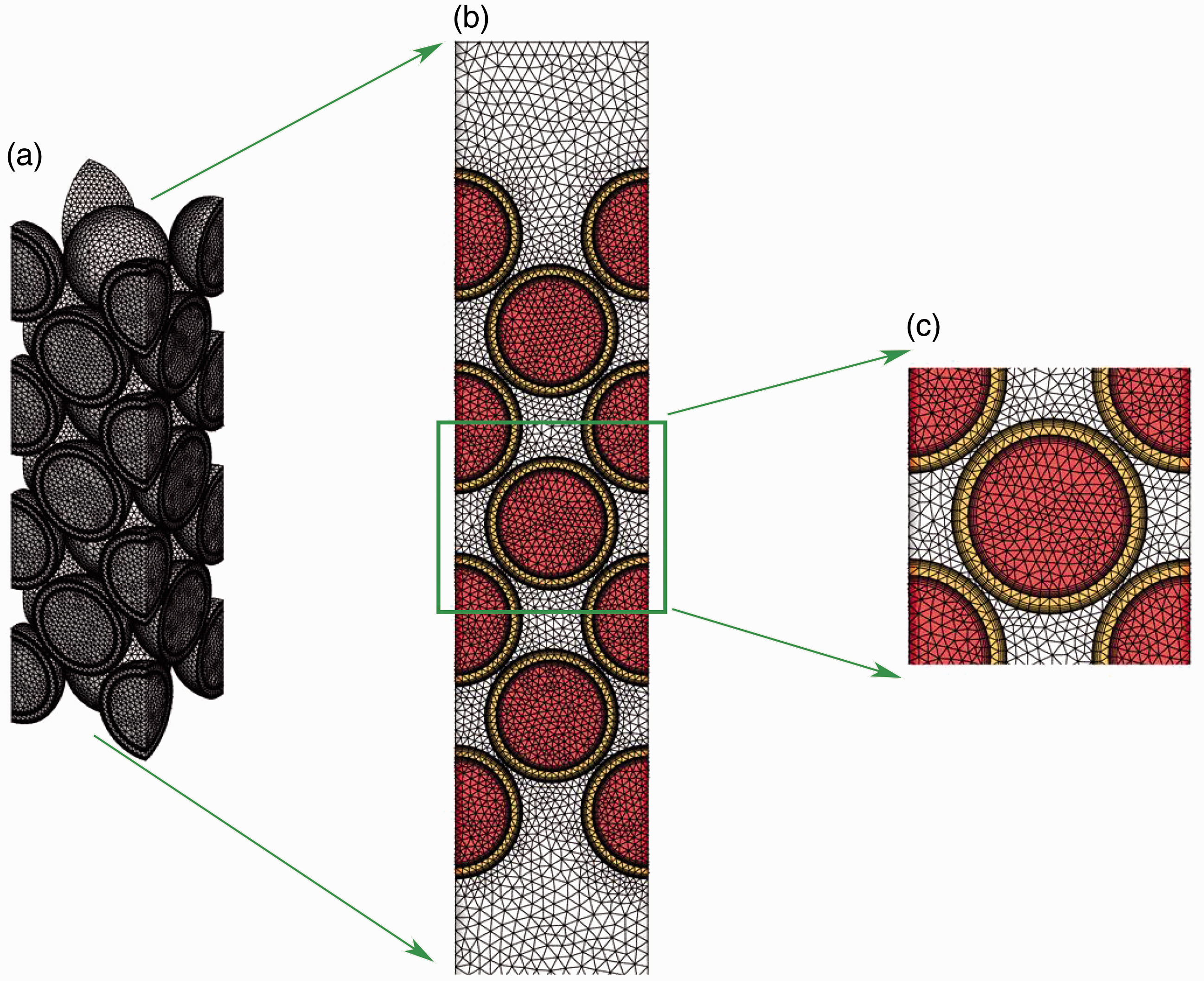
Boundary conditions and some parameters.
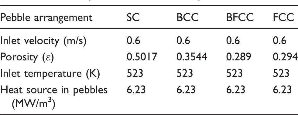
BCC: body-centered cubic; BFCC: combination structure of BCC and FCC; FCC: face-centered cubic; SC: simple cubic.
Four types of the arrangements, SC, BCC, FCC, and BFCC. BCC: body-centered cubic; FCC: face-centered cubic.
Results and discussion
Results of four different arrangements
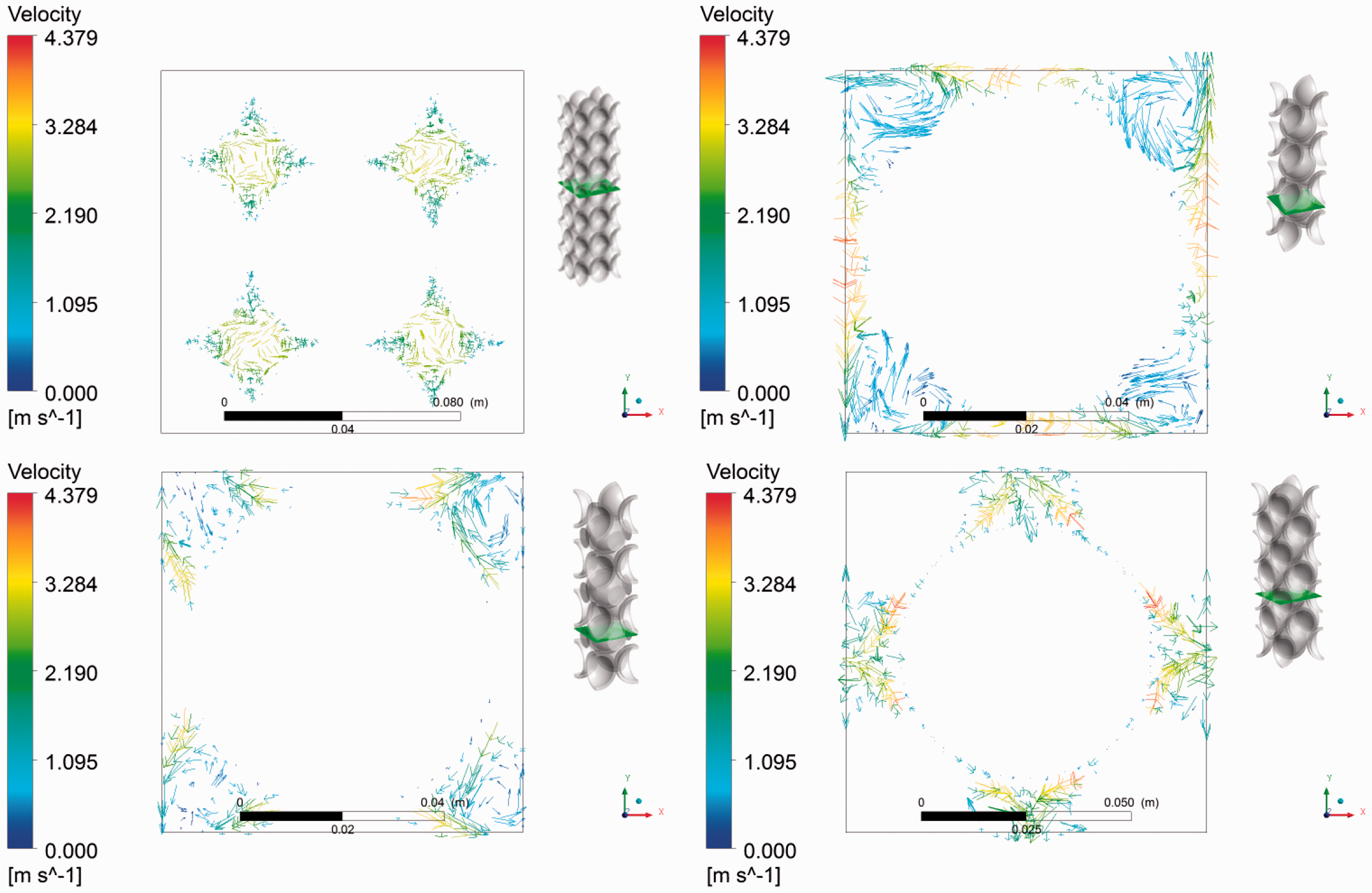
Figures 3 and 4 compare the results of SC, BCC, BFCC, and FCC constructed reactor core for flow fields and relevant thermal distribution. The global velocity in four cases is shown in Figure 3. The color index represents the velocity magnitude. Uniform and slow intake flow accelerates when it flows through the pebble structure in both four cases. The color index reveals that the SC arrangements fluid domain has the least average velocity. For BFCC and FCC, we can see that the maximum velocity is formed in the gaps between pebbles. From the wake, we can know that the direction of velocity is changed after flowing through the pebbles and may cause a sign of oscillation in the end. This is attributed to the curved surface of the pebbles. The He gas flows along the pebble surface and separated at some points, which will shed vortex. Each of the four arrangements, SC, BCC, BFCC, and FCC is not more compact than the next, whereas with higher porosity than the next. Hence the flow area is decreased, and the velocity increases obviously.
Three-dimensional view flow fields of SC, BCC, BFCC, and FCC constructed reactor core. BCC: body-centered cubic; BFCC: BFCC: combination structure of BCC and FCC; FCC: face-centered cubic; SC: simple cubic. Cross-sectional view of flow fields of SC, BCC, BFCC, and FCC constructed reactor core.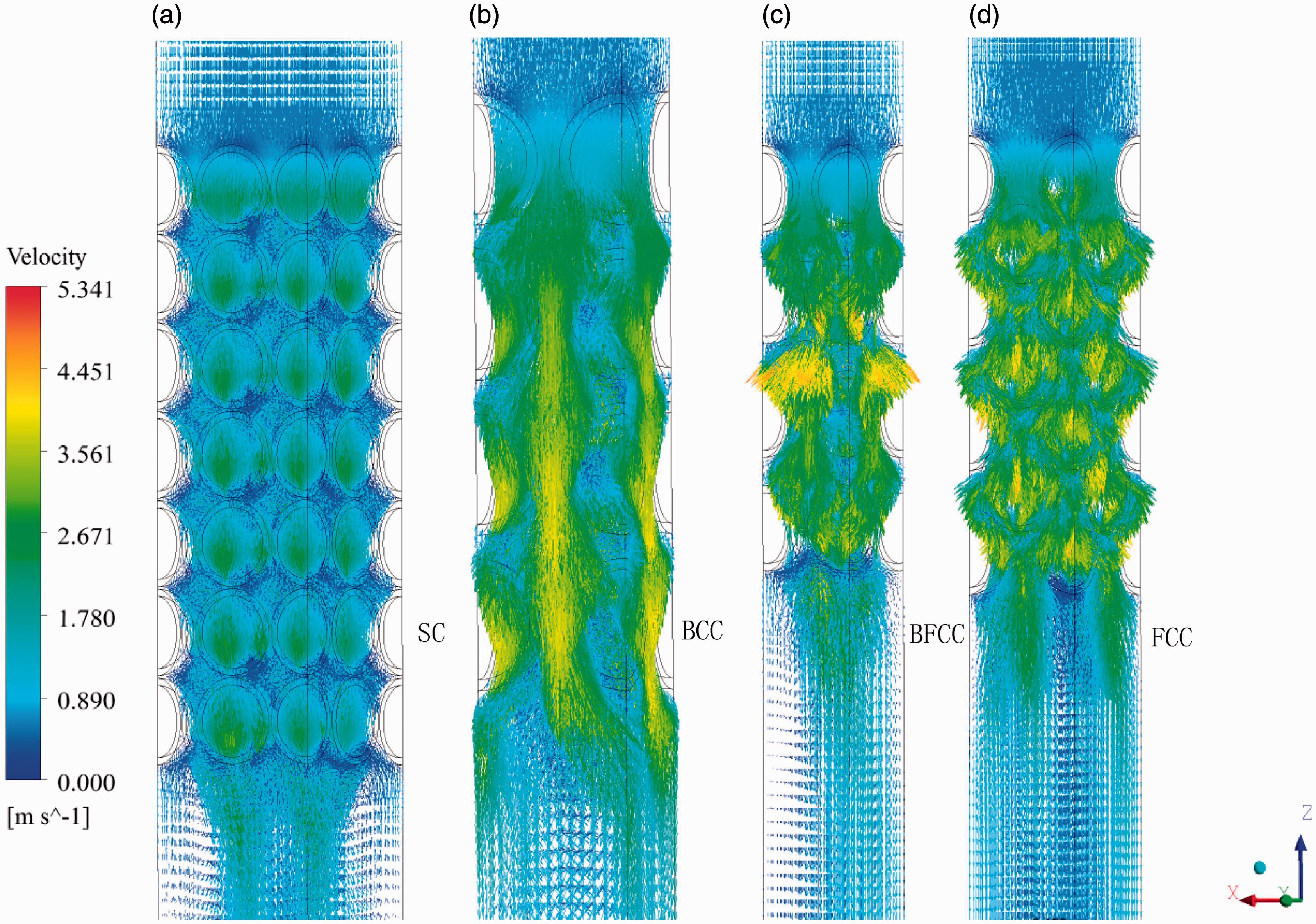
The effect of Reynolds number on the drag coefficient and heat transfer condition
To investigate the effect of fluid Reynolds number on the drag coefficient, we assumed different velocity property of fluid to change the inlet Re. It ranges from 2000 to 7000. Then we use the simulation data to fit correlations. For each arrangement, we set 34 Re numbers and obtained the corresponding drag coefficient to find relationships. The simulation results and predicted curves are shown in Figure 5. The predicted correlations are as follows
The fitted correlations for drag coefficient Cd.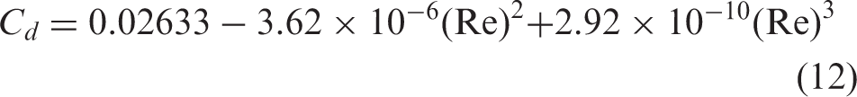
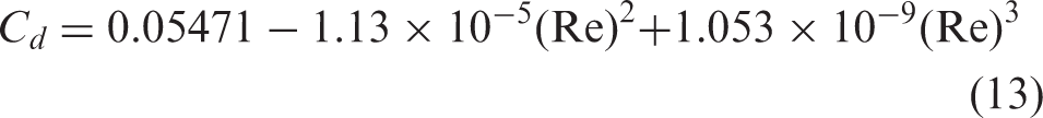
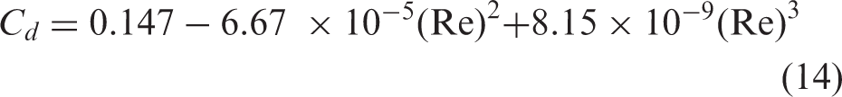
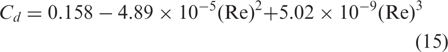
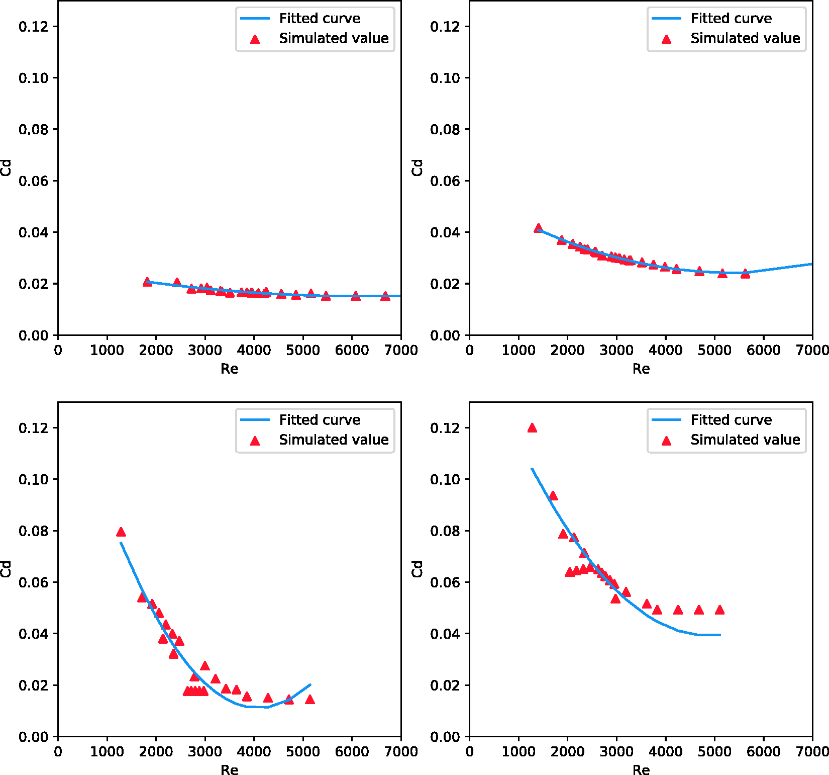
For a selected arrangement, Cd varies with Re due to boundary layer interaction. The increase of Re may cause an increase of frictional resistance. But a compact arrangement of pebbles may have a higher form of resistance. Figure 6 shows the Nu number and temperature for center pebble of BCC lattice, corresponding to different Re. High Re number can result in higher Nu number. The predicted values of Nu number under a thermally fully developed condition can be obtained by KTA correlation.
10
For both pebble arrangement, it can be described as follows: if r is the porosity of pebbles, it is suitable when porosity ranges from 0.36 to 0.42.
7
Nu number and temperature for center pebble of BCC lattice, corresponding to different Re.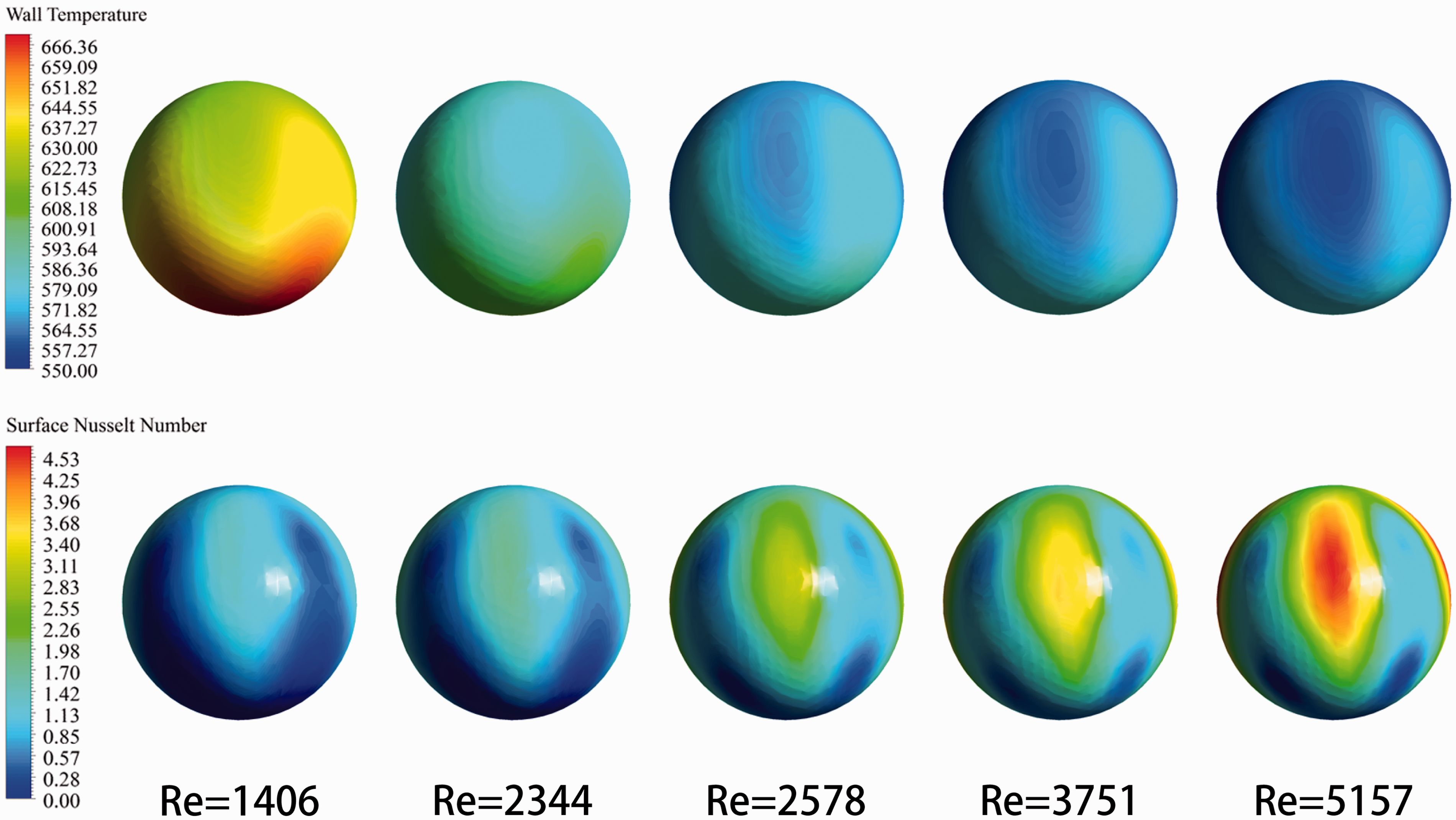
Pollutant dispersion analysis
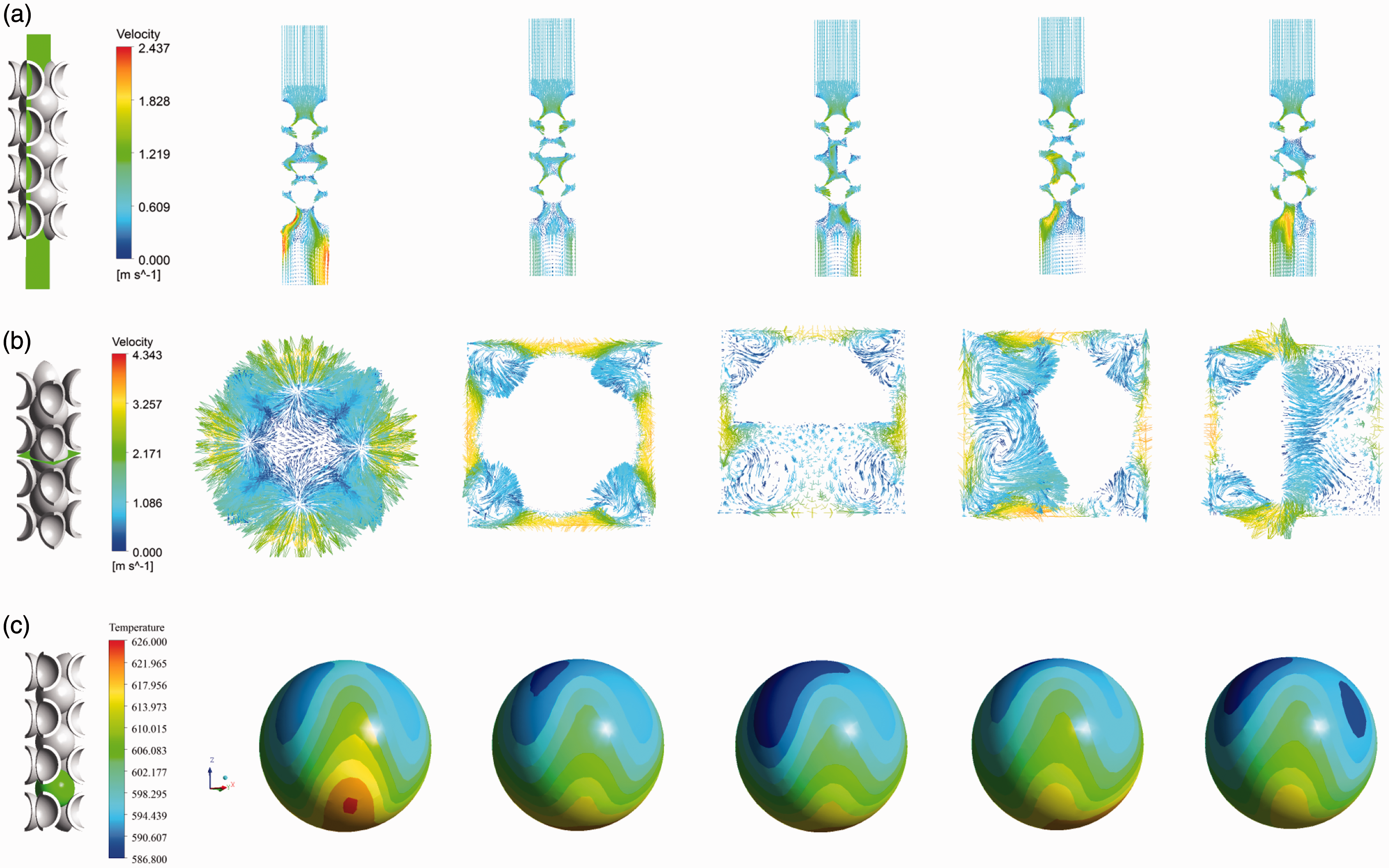
When loading or changing fuel elements in the reactor, some fuel elements may be damaged. A broken fuel element can change the local flow pattern and the secondary flow, which will induce heat transfer and cause some local hot spots. In order to investigate the influence that the broken fuel elements will bring, we assumed that half fuel elements are located in an assumed arrangement in different directions as shown in Figure 7. Figure 8(a) and (b) shows the velocity of the selected vertical and the secondary flow on the selected horizontal plane. Figure 8(c) is the temperature distribution of the sixth layer of BCC lattice. Figure 8 indicates that a broken sphere element will cause flow feeder irregularity. It also has a significant effect on secondary flow and wake. This may lead to some hot spots in the following layer of pebbles.
A broken half fuel elements located in a arrangement in different directions. The velocity on the selected vertical plane (a) and the secondary flow on the selected horizontal plane (b), and the temperature distribution of the sixth layer of BCC lattice (c).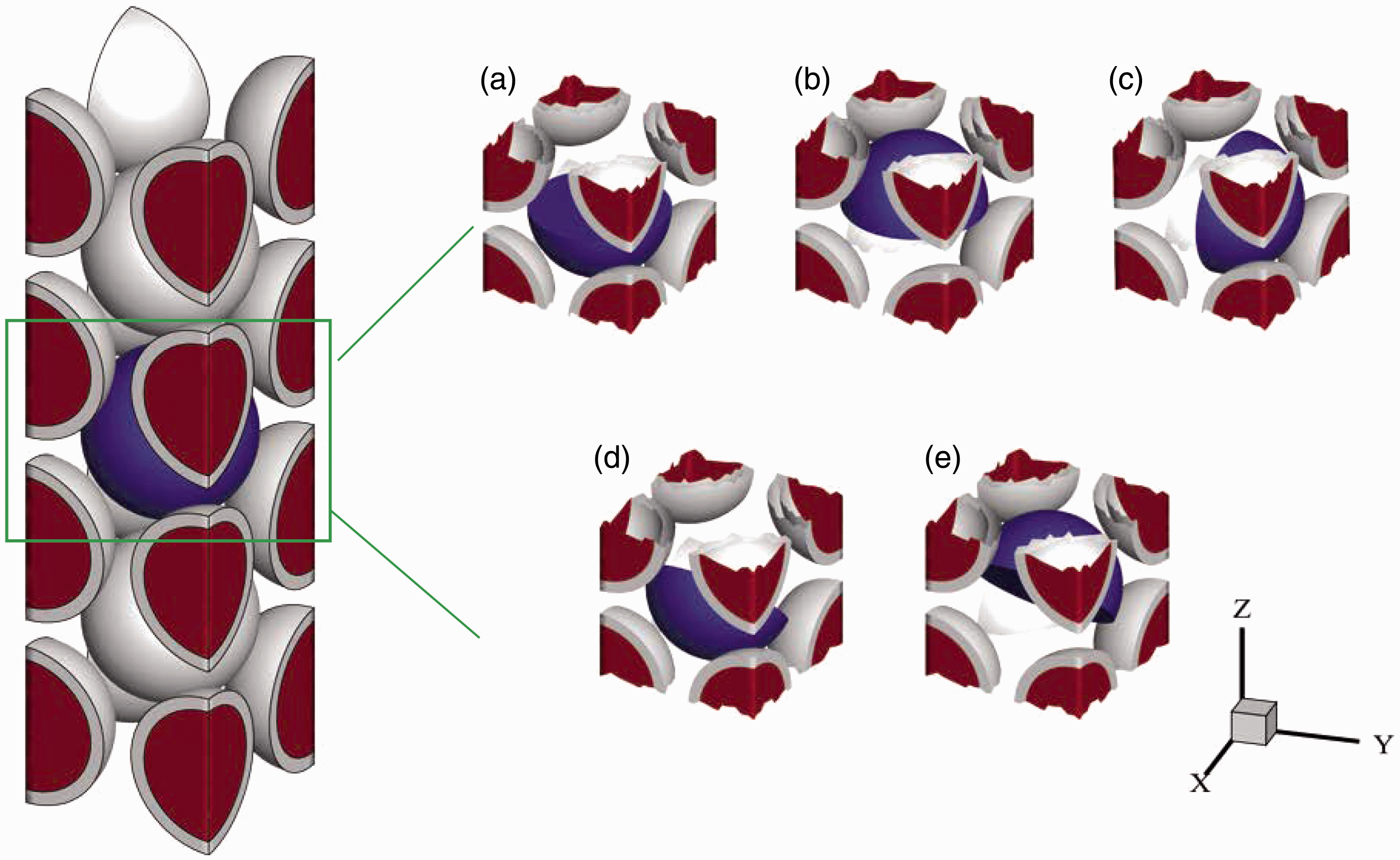
Conclusions
The main purpose of this paper is to investigate the thermal hydraulic characteristics of HTGR. He is used as the coolant. The artificial space is used between adjacent pebbles for four different arrangements of mesh model. The influences of the broken fuel pellet are also analyzed in this article. Some conclusions can be obtained as follows:
The thermal-hydraulic characteristics of HTGR using SC, BCC, BFCC, and FCC are numerically investigated in this article. The distribution of velocity vector and secondary velocity in selected horizontal plane is obtained. With the same inlet velocity, the flow velocity between pebbles is different. With the compact arrangement, the flow area is small and velocity between gaps is higher. This may lead to higher heat transfer coefficient and lower pebble surface temperature. With different inlet velocity and coolant property, the drag coefficient is changed. We found the correlations for estimating Cd for four different arrangements. With the same inlet Renumber, the compact arrangement may correspond to higher Cd. Furthermore, with the same arrangement, the higher Re number tends to correspond to lower Cd. A broken fuel sphere can remarkably influence the flow field. A broken fuel element is placed in a BCC fluid domain in five different directions. The influence imposed to the flow and heat transfer has been obtained. A broken fuel element can result in uneven flow and may change the heat transfer condition to adjacent pebbles and cause hot spots. It is considered that the damage to the fuel elements should be avoided during loading and unloading process.
Footnotes
Declaration of conflicting interests
The author(s) declared no potential conflicts of interest with respect to the research, authorship, and/or publication of this article.
Funding
The author(s) disclosed receipt of the following financial support for the research, authorship, and/or publication of this article: The authors are grateful for the support of this research by the National Natural Science Foundations of China (Grant No. 51576211), the Science Fund for Creative Research Groups of National Natural Science Foundation of China (Grant No. 51321002), the National High Technology Research and Development Program of China (863) (2014AA052701), and the Foundation for the Author of National Excellent Doctoral Dissertation of PR China (FANEDD, Grant No. 201438).