
Abstract
Numerical study of multiphase swirl flow induced by helical insert inside the supersonic nozzle is investigated as applied in sandblasting systems. The finding of this research is crucial in improving the performance of abrasive blasting systems by reducing operation time and saving energy. Simulations are performed with Reynolds Stress Model turbulence modelling to capture anisotropy inside the flow. To simulate particles inside the nozzle, discrete phase model has been applied. The multiphase Eulerian method did not provide accurate results on modelling particles with small volume fraction (<10%), and also it was not capable of modelling particles interaction. The analyses are performed at three inlet pressures (2, 3 and 4 atm) with constant mass flow rate for particles. The results show that swirl effect increases the mixing feature of the flow, and therefore increases the cleaning area on a working surface. Furthermore, with swirl there was less reduction in maximum velocity compare with single phase simulations, hence particles will have greater speed at the exit of the nozzle.
Keywords
Introduction
Investigation of supersonic flow inside converging-diverging nozzles has been the subject of several numerical and experimental studies in the past1,2 because of their great application in propulsion, steam turbines and sandblasting, but there is not much research on the effect of swirl flow inside converging-diverging nozzles. Swirling flows are very common in technical applications, such as turbo machinery, cyclone or separators, and they require rather sophisticated modelling. Effect of swirl inside nozzle can intensify heat and mass transfer and improve mixing features of the flow by increasing turbulence and vorticity, which can be useful not only in sandblasting applications, but also in combustion injectors for flame stability 3 or jet engines for noise reduction,4,5 and changing the shock structure and its interaction with boundary layer. These several viscous and compressible phenomena affect the flow behaviour inside and outside of the nozzle.
The need for accurate understanding of flow features inside nozzle with swirl is important to predict its effect. Since experimental data for the swirl flow inside high-speed nozzle are scare; the numerical results are vital for understanding the flow and further analyses. This study is based on standard sandblasting nozzle, where single phase simulations on it with helical insert was investigated by Eslamian et al. 6
Sandblasting
Sandblasting, which is formed from nozzle with a mixture of air, water and abrasive media, has been used for many industrial applications such as cleaning or removing coating from different type of surfaces, surface strengthening and surface modification 7 and can provide perfect surface treatment for different materials like plastics, composites, steel, etc. 8 In sandblasting treatment, abrasive material is accelerated through a nozzle due to the pressure difference. As a result, in any sandblasting method nozzle geometry, jet velocity and impact angle 9 are the most important parameters to improve effectiveness of sandblasting system. There are different studies and patents to improve sandblasting and make the process faster and more efficient, but none of them are working on fluid dynamic and pressure distribution inside nozzle.
Sandblasting machines operate at a pressure range from 30 to 130 psi. However, for the most applications they are operating at pressures less than 60 psi to avoid damaging a working surface and to save energy. Although the experimental study by Seavey 10 for abrasive blasting in excess of 100 psi at the nozzle, shows that by increasing the pressure from 60 psi to 140 psi, productivity and efficiency continues to increase; however, as the discharge pressure increases, the fuel consumption increases as well to provide horsepower requirements for compressor system.
Multiphase flow
The two fluid model, Eulerian–Eulerian (E–E), can in principle be used to solve any multiphase flow regime, considering adequate closure relations for the momentum equation, are provided. However, Eulerian–Lagrangian (E–L) model is suitable only for disperse flows. In the E–E approach, the flow variables are functions of space and time, and hence are represented as fields. In the E–L method, particles are considered individually, and the position and velocity of each particle is only a function of time. Therefore, in E–L approach, Navier–Stokes equations are solved for the continuous phase (similar to E–E method). However, for the disperse phase positions and velocity of each particle is obtained from Newton’s second law.
Granular materials that are created from crushing or mining operations are generally highly angular or plastic abrasive media usually in a cylindrical shape. However, most of computational analyses of multiphase granular flows are performed for perfect spheres. Some studies such as Vu-Quoc et al. 11 and Džiugys and Peters 12 have worked on elliptical shaped particles that are created from a combination of spheres, or the study by Hopkins and Shen 13 which has worked on spherical and disk shaped particles.
Hou et al. 14 have studied numerically inside and outside of the abrasive water jet nozzle. The Eulerian two-phase model has been adopted to simulate flow fields. Although the results were acceptable, Hou et al. 14 have also demonstrated that the Eulerian two-phase model is not able to correctly predict the velocity of solid phase.
Van der Hoef et al. 15 have reviewed numerically gas–solid fluidised bed on the basis of whether a Lagrangian or an Eulerian model is used for the gas or particulate flow. It is suggested that the Lagrangian–Lagrangian (L–L) model, where both gas phase and solid phase are represented by particles, is useful only for gas–solid flow at extremely small scales, in which the thermal fluctuations of the gas phase have an influence on the motion of the large particles (Brownian motion). On the other end of the scale is E–E approach, in which both gas phase and solid phase are solved based on continuum description. The interaction between the two phases is resolved by drag force correlations which depends on relative velocity of phases and volume fraction of the solid phase. The problem with this model is that it does not accurately model gas–particle and particle–particle interactions. To overcome this drawback, the E–L model (or discrete phase model (DPM)) has been proposed. Van der Hoef et al. 15 have concluded that for gas–solid fluidised bed the DPM provides the best results and E–E model can simulate fluidised beds only at engineering scales (height 1–2 m), where particle size are at least 1 mm.
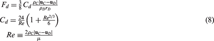
Gas–solid multiphase flows are classified in two dense or dilute regimes. If the volume fraction of particles is less than
Supersonic nozzle
Simulation of solid-propellant rockets with aluminium droplets has been performed by Najjar et al. 17 in which burning of aluminium droplets generates aluminium-oxide smoke. Eulerian formulation for simulation of fine smoke particles has been used in conjunction with a Lagrangian formulation for the larger aluminium droplets.
The study by Li and Li
18
has numerically analysed the behaviour of spray particles in the cold spray gun nozzle. Two-phase flow DPM relation along

Two types of separation pattern can be observed in a supersonic nozzle, the free shock separation (FSS) and the restricted shock separation (RSS). In FSS flow separates from the nozzle wall due to oblique shock, and the separation zone continuously to exit a nozzle as a free jet. In RSS, the separation is restricted to a limited size and will reattach to a nozzle wall before exit of a nozzle. Both FSS and RSS can be observed in a nozzle at different operating conditions, which highly depends on shock boundary layer interactions.
Swirl flow
Swirling flow in choked de Laval nozzle was investigated numerically by Pandolfi. 20 The swirling flow is achieved through surface located at the inlet of the nozzle. The time-dependent technique for two-dimensional (2D) axisymmetric configurations has been deployed. The centrifugal forces due to the tangential velocity act in increasing the pressure at outer boundaries and in decreasing it at the inner boundaries.
Liu et al. 21 have investigated supersonic flow inside adiabatic C-D which was introduced by two identical tangential inlets. The numerical simulations in this study were steady state, and all the flow parameters were time-independent. For boundary conditions, total pressure and temperature with critical mass flow rate were employed. For turbulence modelling Reynolds Stress Model (RSM) was used. It has been concluded that both the axial velocity and the tangential velocity increases and the swirling flow with a large centrifugal acceleration that is produced at the inlet can get through the shock wave at the throat up to the outlet of the nozzle.
A free vortex type swirling flow in a long-circular pipe was investigated experimentally by Kitoh. 22 It has been shown that, based on the tangential velocity distribution, the flow has three regions: wall, annular and core. In the wall region, the only effect that appears is the centrifugal force destabilising. Therefore, the classical mixing length model can predict the flow in wall region. The annular region is characterised by a flow skewness. Tangential velocity in core region was expressed as a sum of forced and free vortex motions. It is difficult to use an analytical approach to predict flow features in this region. It was suggested that using the RSM which can handle anisotropic turbulence will be a more promising tool to predict the flow compared with an eddy viscosity model such as k − ɛ. The core region is characterised by a forced vortex motion, and the flow is dependent upon the upstream conditions. In this region, turbulence motion has very low frequency, and the flow is non-dissipative. Hence, there is a long history effect in core region.
Numerical methods
Geometry
The dimension of the nozzle, for which the flow inside it has been investigated, is shown in Figure 1(a); the length of the nozzle is 200 mm and has three sections. The first (64 mm) is the convergence section; then it is 16 mm with constant 11 mm diameter; and the divergence section length is 120 mm with outlet diameter of 15 mm. This is one of standard geometries, which is being used widely by sandblast companies.
Geometry of: (a) the nozzle; (b) the helical insert; and (c) nozzle and helical insert (all geometries shown here are with zero thickness).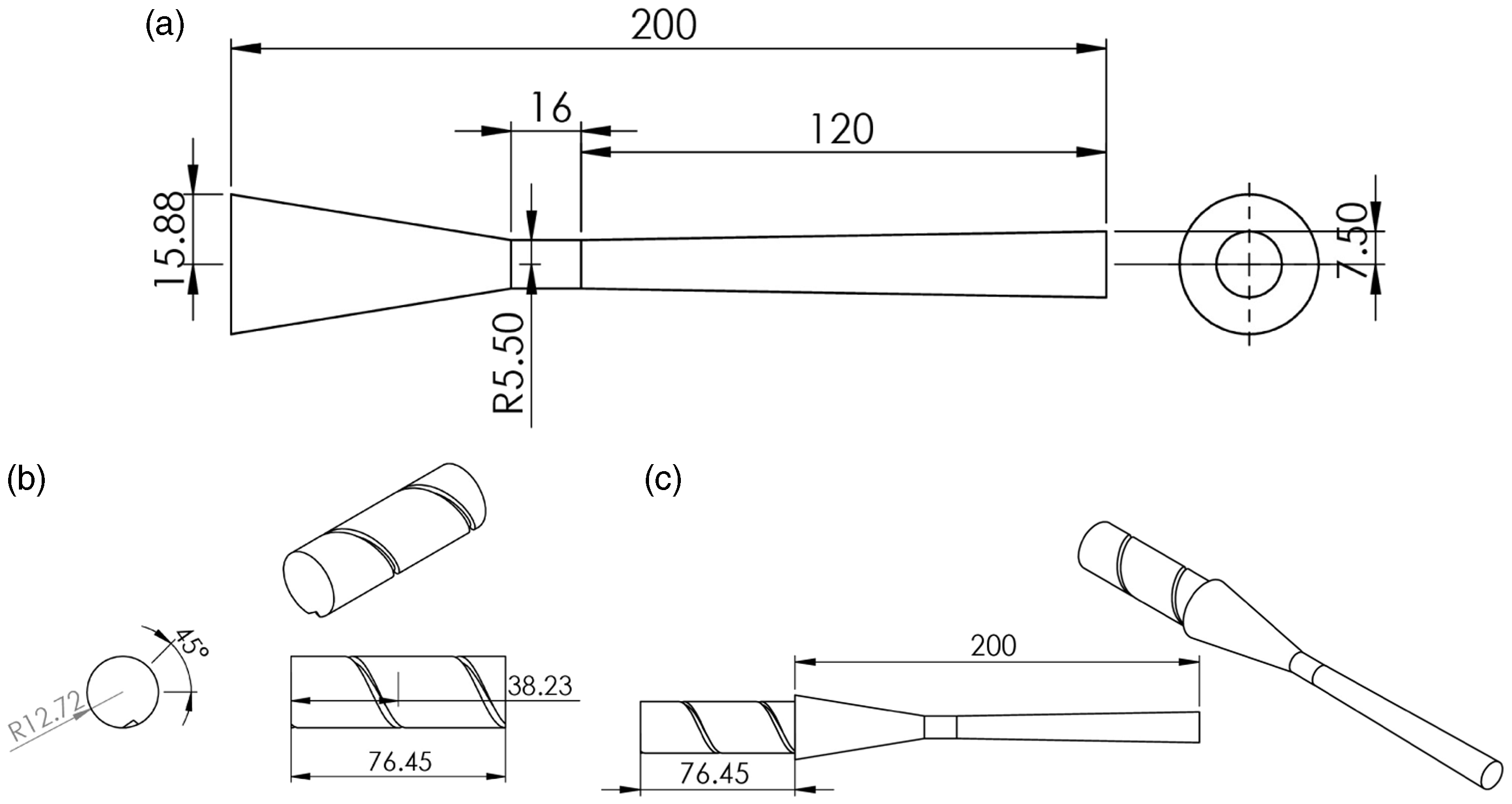
In order to create swirl flow inside the nozzle, a helical insert has been added to the inlet of the nozzle. The geometry is not expensive to manufacture, and it is easy to install on any sandblasting nozzle. The geometry of helical section is shown in Figure 1(b); it has 31.75 mm diameter with a length of 76.45 mm, and the spiral part has two revolutions with start angle of 45°.
The computational domain is presented in Figure 1(c), where the helical insert and nozzle will screw together, with the total length of 276.45 mm. All analyses are with same geometry but different pressure ratios.
Governing equations
The density-based scheme employs the density as a primary variable and extract pressure from the equation of state. The FLUENT package has been used in this study, the density-based solver, solves governing equations (continuity, momentum and energy) simultaneously as a set or vector of equations (equation (2)). For additional scalars, the governing equations will be solved sequentially (segregated) similar to pressure equation. The Navier–Stokes equations for compressible flow in vector mode can be written in conservation form as
23

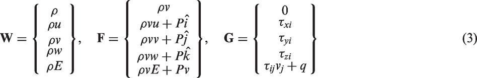
Here, et is total energy per unit mass, and q is the heat flux. The inviscid flux vector

The partial differential equations are solved in transient mode with implicit density-based solver. The discretisation method for the gradient is least squares, and for flow is third-order MUSCL scheme to capture shock wave properties.
Discrete phase model
In DPM, each discrete phase element is tracked through flow domain. The trajectory of particles is obtained by solving Newton's second law of motion for each particle


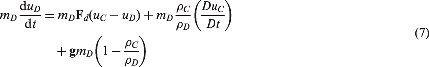
The difficulty in Lagrangian approach lies in the fact that the continuous and dispersed phases are closely coupled. So, the continuous phase flow will affect the motion and distribution of particles, and also particles will influence the flow characteristics of continuous phase. The motion of continuous phase is described in an Eulerian framework (fixed in space), while the motion of particles is described in a Lagrangian framework (fixed to particle). Therefore, in this research, two-way coupling is applied to simulations, where particles interact with continuous phase.
Turbulence modelling
The two equation turbulence models are incapable of capturing anisotropy of the normal stresses and computing the effect on the turbulence of extra strain and body forces. The RSM models28,a consider all these effects by solving transport equations for the Reynolds stresses, together with an equation for the dissipation rate. This will add extra seven transport equations for three-dimensional (3D) flows. b On the downside RSM will increase the amount of storage and CPU usage run time significantly.
The exact transport equation of Reynolds stress (


The rotation term is formulated as


The dissipation rate of turbulence is calculated by
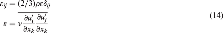
The scalar dissipation rate is modelled with the same equation of standard
Second-order upwind discretisation scheme has been adopted for turbulence modelling.
The boundary layer is almost laminar in viscous sublayer and fully turbulent in log-law region. Turbulence models are valid for fully turbulent flows, therefore semi-empirical formulas ‘wall functions’, are used to model flow properties between the wall and log-law region. Reynolds numbers in this study are reasonably high, so using wall functions will provide proper accuracy without limiting computing resources.
Results
As explained previously, Eulerian model is not yet capable of accurately solving the interaction between fluid (air) and solid (particles) in such a high-speed flow and low-volume fractions (<10%). On the other hand, Lagrangian method c is accurate and well tested for solid dynamic calculations. 29
Olivine properties.
Sandblasting machines operate at different pressures and mass flow rates. The mass flow rate for abrasive particles could vary from 0.005 to 0.05
Inlet pressure 2 atm
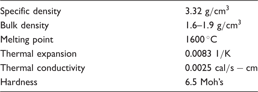
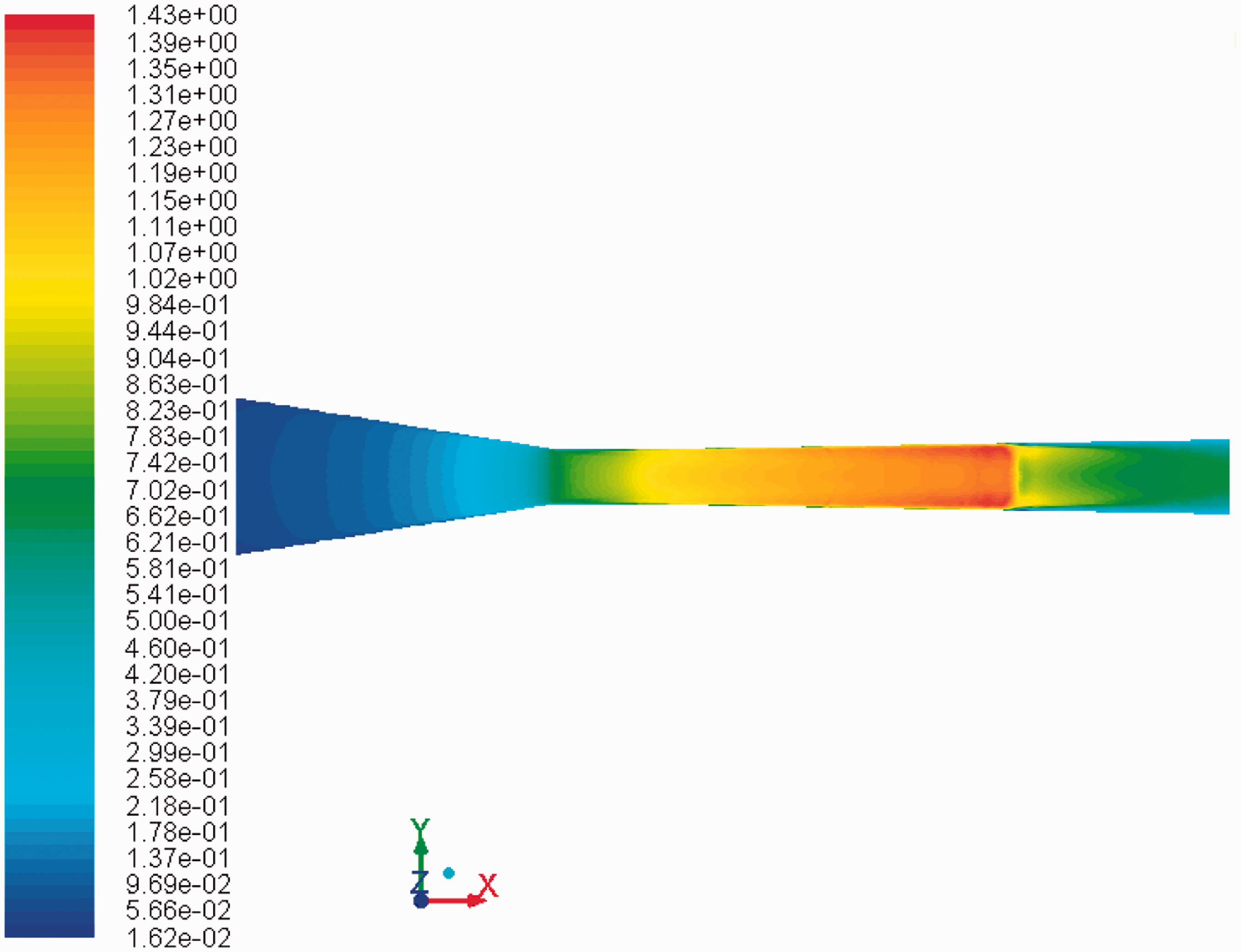
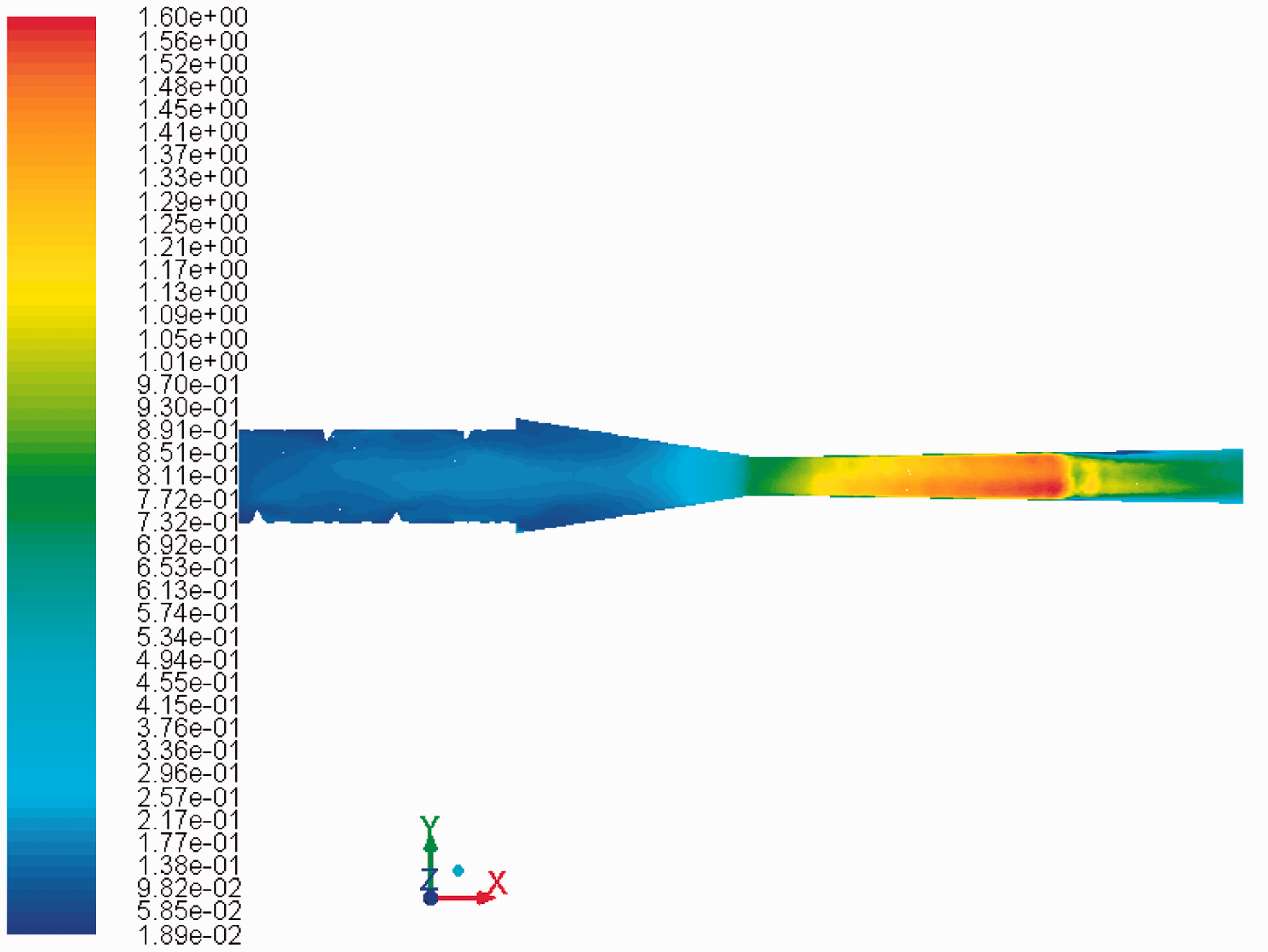
Mach number contours at inlet pressure 2 atm for the nozzle without helical insert is shown in Figure 3. Compared with single phase simulation (Figure 2(a)), there is just one strong shock wave without any multiple shock and expansion wave after the main Mach disk. There is lower velocity area at the centre due to high concentration of sand (olivine) particles. The maximum velocity has reduced from Mach 1.8 to Mach 1.4, which means a 22% reduction. On the other hand, the maximum velocity of DPM with helical insert (Figure 4) has not changed compared with single phase simulation (Figure 2(b)) from Mach 1.6. The Mach number contours for swirl condition with particle injection shows that the structure of shock waves has not changed, and still there is series of shock waves and expansion fans after the main shock wave. However, the separation zone has changed, and there is a small FSS region at the top and an RSS region on the lower wall.
Mach number contours for single phase simulations of the nozzle: (a) without helical insert, and (b) with helical insert at inlet pressure 2 atm.
6
Mach number contours of DPM for the nozzle without helical insert at inlet pressure 2 atm. Mach number contours of DPM for the nozzle with helical insert at inlet pressure 2 atm.
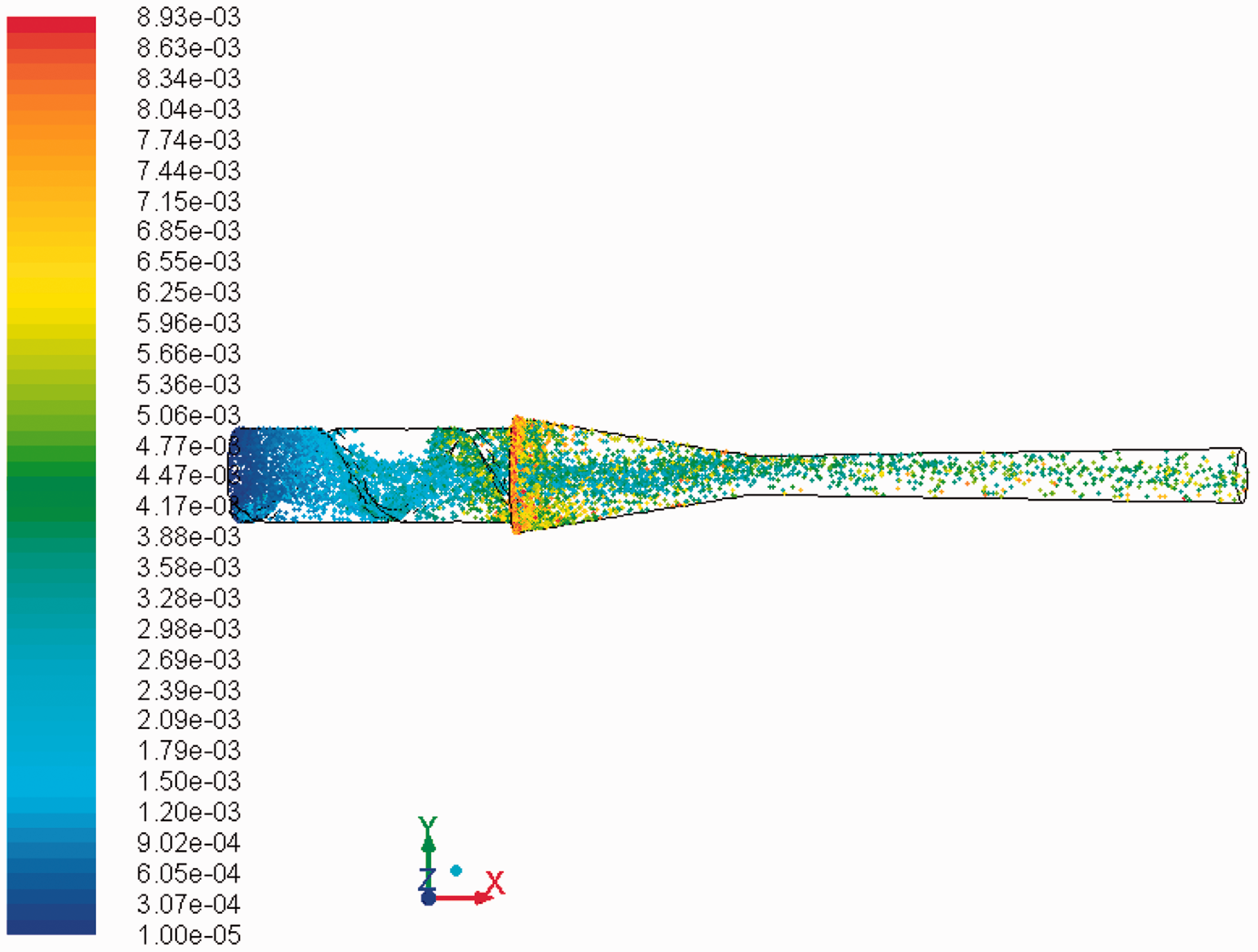
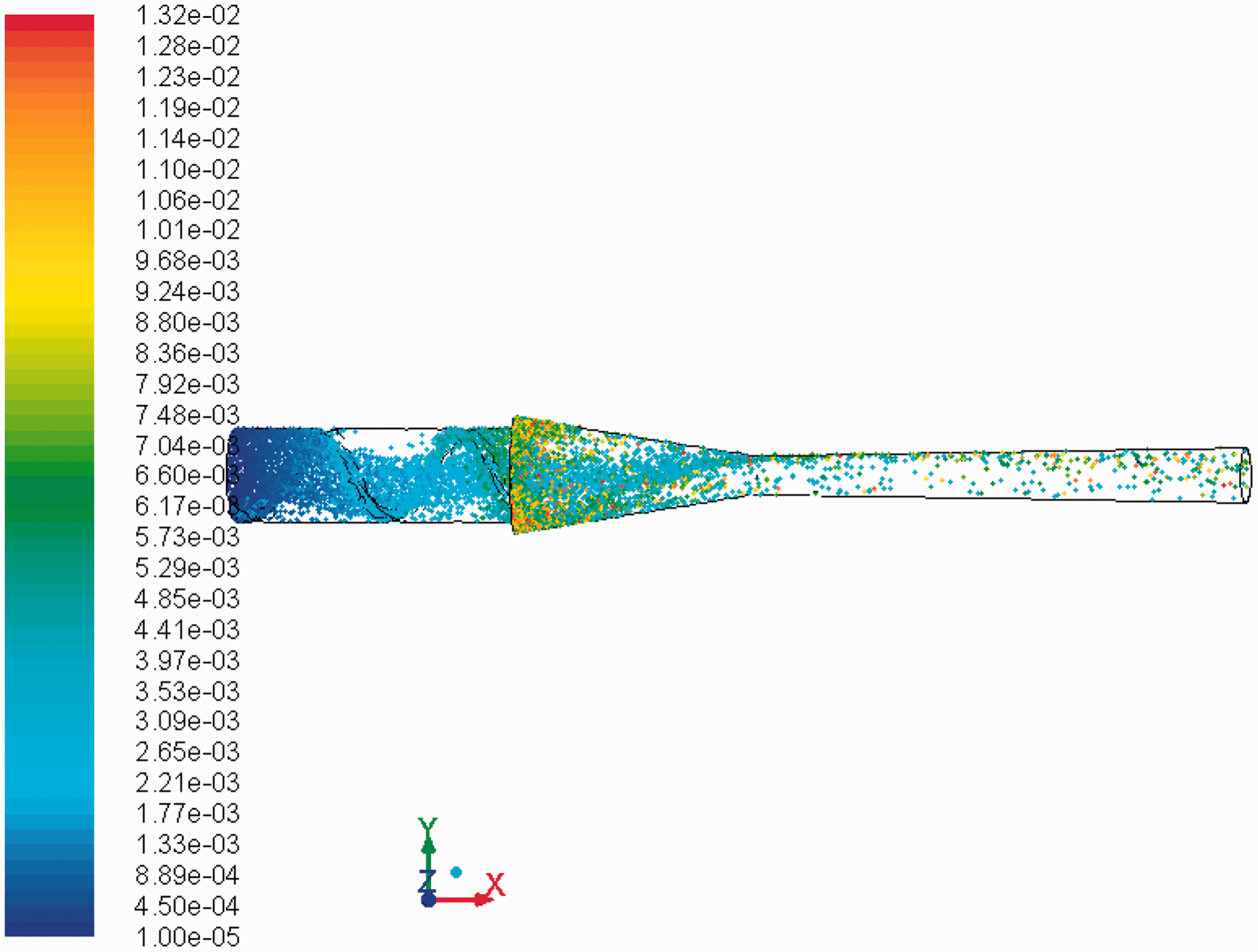
Particle distribution for the nozzle without helical insert is illustrated in Figure 5. Without swirl condition, the particles are more towards centre; however, by adding the swirl effect to the flow particles they are better distributed and are not concentrated at the centre of the nozzle (Figure 6). This will be very helpful to avoid damaging a surface.
Particle trace coloured by particle residence time for the nozzle without helical insert at inlet pressure 2 atm. Particle trace coloured by particle residence time for the nozzle with helical insert at inlet pressure 2 atm.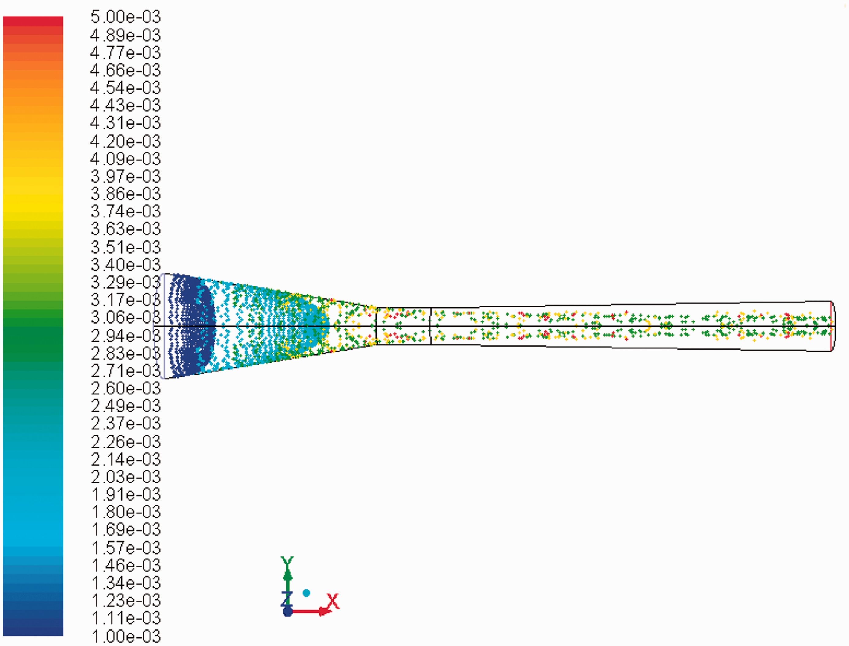
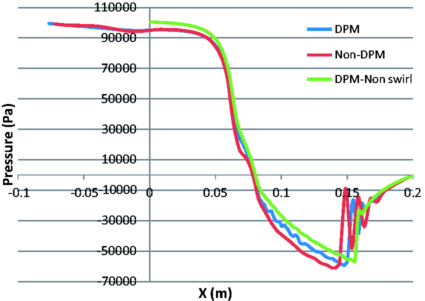
Pressure along centre of the nozzle without helical insert is sketched in Figure 7. By injecting particles, the structure of shock waves has been changed. Instead of having multiple shock waves and expansion fans there is just one strong shock wave; after the pressure it will gradually increase until it reaches atmospheric pressure at the outlet. In Figure 8, the pressure along centre of the nozzle with helical insert is plotted. There is a very small change in pressure behaviour compared with single phase simulation, apart from some oscillations with very small amplitude before shock waves. There is a small movement on shock location as well, where first shock wave has moved forward.
Pressure along centre of the nozzle without helical insert for DPM at inlet pressure 2 atm. Pressure along centre of the nozzle with helical insert for DPM at inlet pressure 2 atm.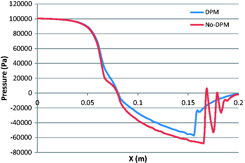
Inlet pressure 3 atm
Mach number contours with the enabled DPM for the nozzle without helical insert is represented in Figure 9. In comparison with single phase simulations, the maximum velocity has reduced by 13% from Mach 1.55 to Mach 1.77. However, in the nozzle with helical insert, the maximum velocity is almost unchanged at Mach 1.9 for both DPM (Figure 10) and single phase simulation (Figure 11). This proof there is much higher momentum in the swirling flow inside the nozzle even with the particles.
Mach number contours of DPM for the nozzle without helical insert at inlet pressure 3 atm. Mach number contours of DPM for the nozzle with helical insert at inlet pressure 3 atm. Mach number contours for single phase simulations for inlet pressure 3 atm. Swirl contours are for two time-steps: (a) t = 0.8e − 2s, and (b) t = 1.8e − 2s.
6
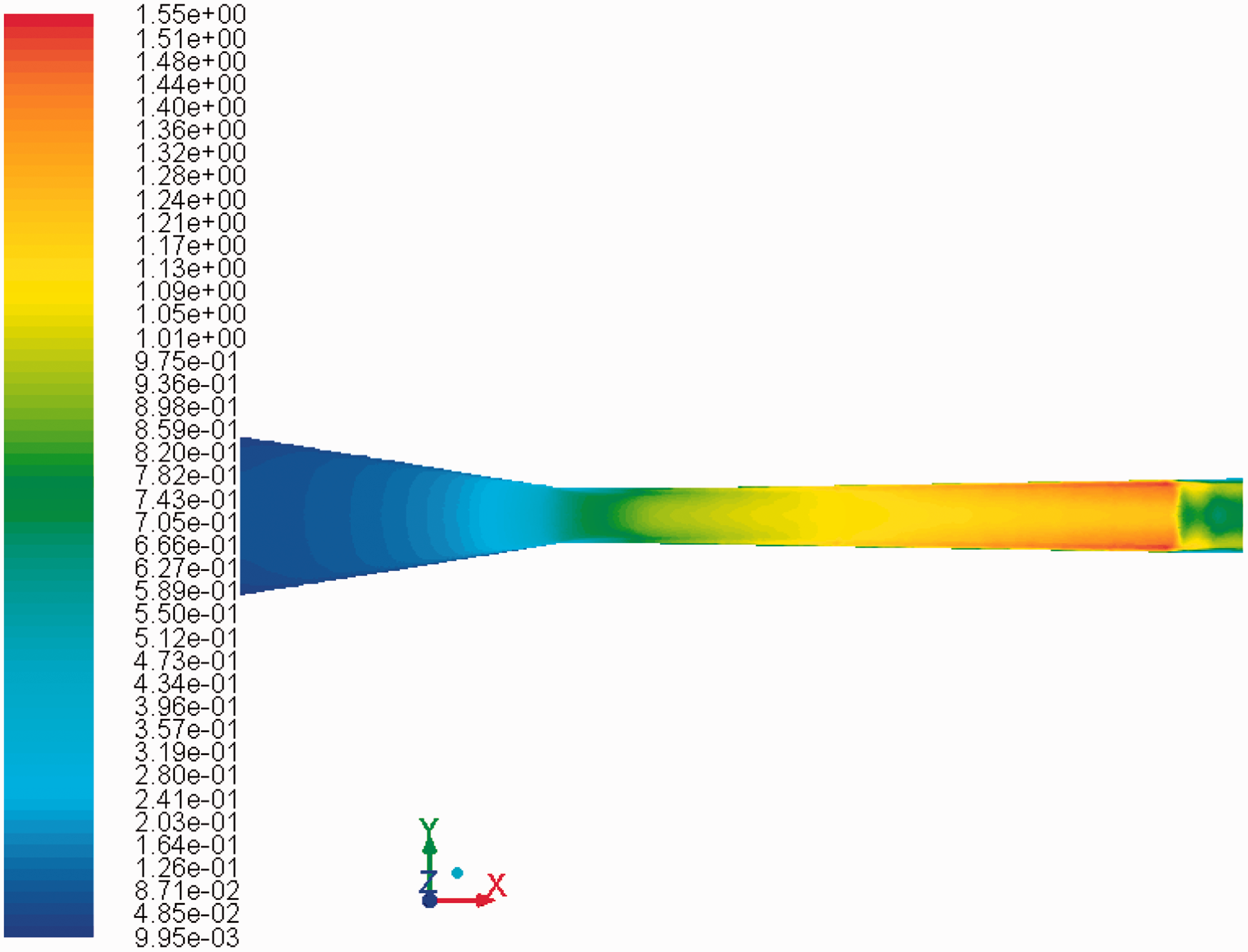
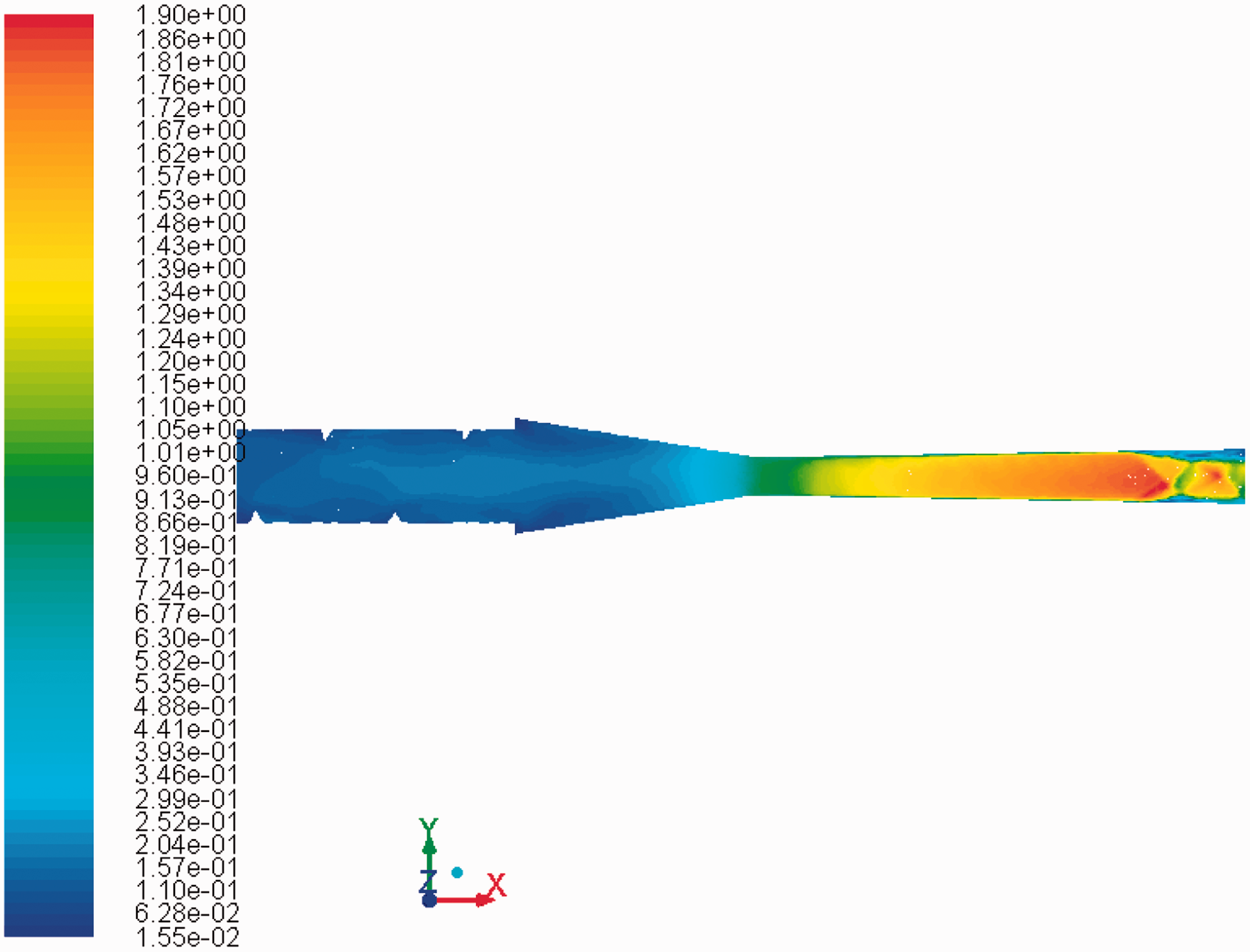
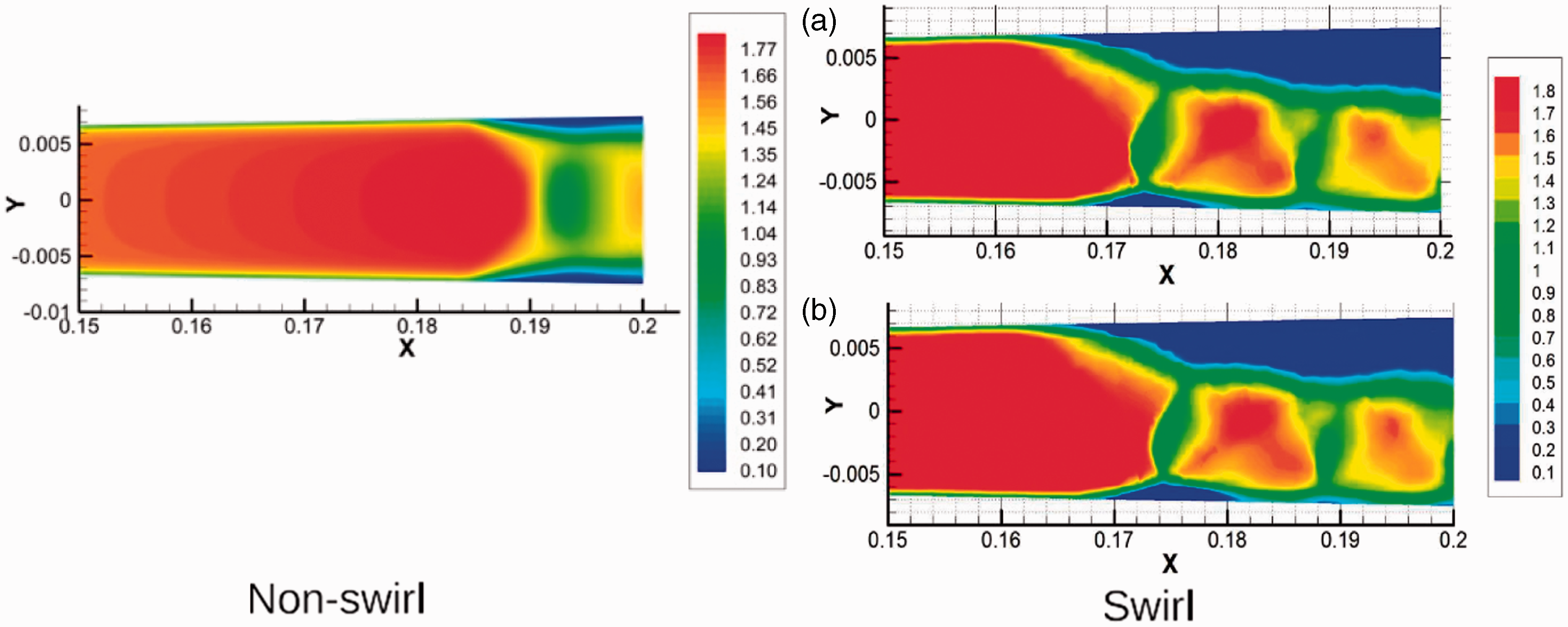
Figure 9 shows that there is some lower velocity zone at the centre of the nozzle due to high concentration of abrasive particles, but this is not visible in Figure 10 which verifies particles are not concentrated at the centre. Both non-swirl and swirl Mach contours with the Lagrangian approach do not show any unsteady pattern inside the domain.
From Figure 10 it is clear that both FSS separation zone at the top and RSS recirculation zone at the lower wall exist similar to single phase simulation (Figure 11), although these separation areas are much smaller. In the nozzle without helical insert, the separation zone has been removed due to particle injection.
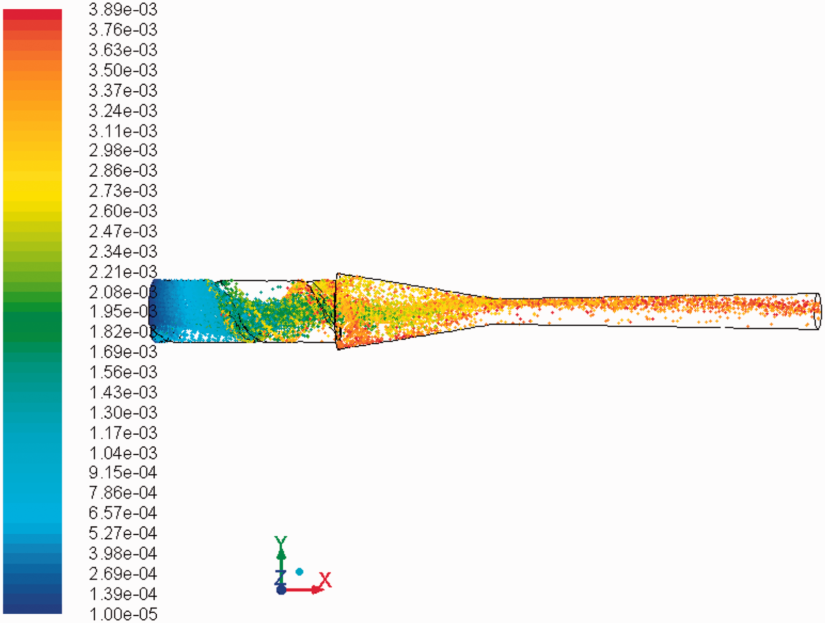
Particle distribution for the nozzle without helical insert at inlet pressure 3 atm is very similar to inlet pressure 2 atm, where most of olivine particles are concentrated at the centre of the nozzle in diverging section (Figure 12). Particles in the nozzle with helical insert are distributed more evenly, although there is some concentration zone after the helical insert, showed by red particles, due to the diameter difference between the nozzle inlet and helical insert outlet (Figure 13).
Particle trace coloured by particle residence time for the nozzle without helical insert at inlet pressure 3 atm. Particle trace coloured by particle residence time for the nozzle with helical insert at inlet pressure 3 atm.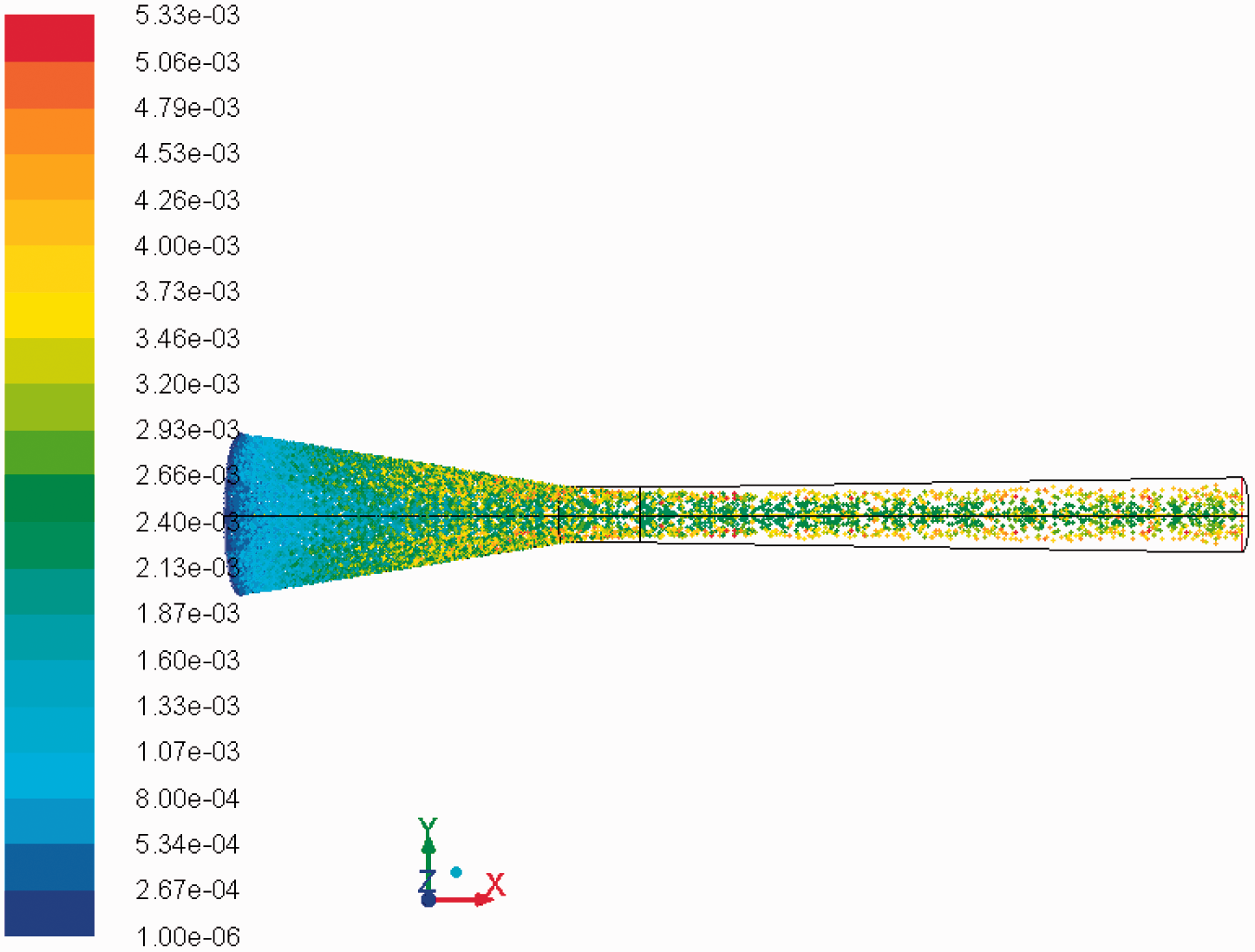
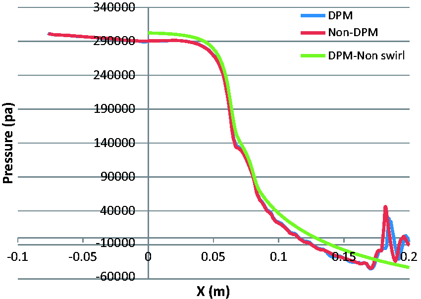
Pressure along centre of the nozzle without helical insert is plotted in Figure 14. In DPM, the shock wave is much weaker, and the pressure is gradually increasing to get to the atmospheric pressure at the outlet. This is not favourable effect as shock waves at the exit of the nozzle will provide mixing effect. On the other hand for the nozzle with helical insert, the shock waves are almost unchanged (Figure 15). Similar to inlet pressure 2 atm, the first shock wave has moved forward, and there are small oscillations behind the first shock.
Pressure along centre of the nozzle without helical insert for DPM at inlet pressure 3 atm. Pressure along centre of the nozzle with helical insert for DPM at inlet pressure 3 atm.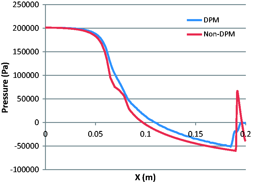
Inlet pressure 4 atm
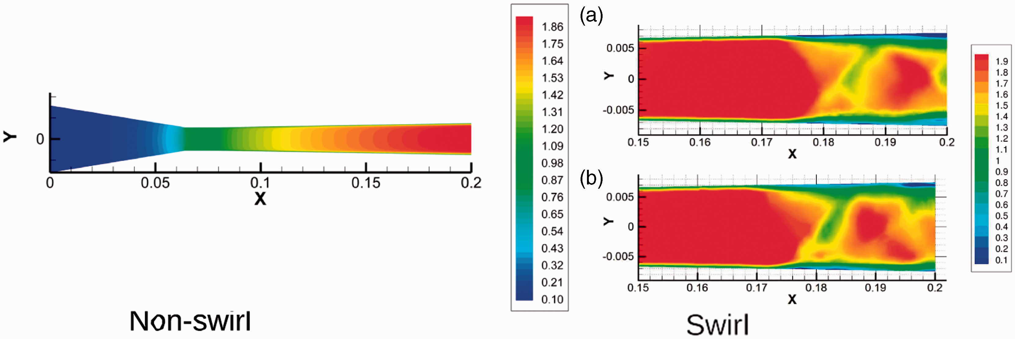
Mach number contours for inlet pressure 4 atm are shown in Figures 16 and 17. In single phase simulation without helical insert, all the shock waves were outside of the nozzle (Figure 18), with the DPM as well, all the shocks are outside of the nozzle, but there is an 8% reduction on maximum velocity. Similar to lower pressure DPMs for the nozzle without the helical insert, the air closer to the nozzle wall has a higher velocity than the air toward the centre of the nozzle; however, at inlet pressure 4 atm; Figure 16) the velocity change from centre toward the nozzle wall is smaller.
Mach number contours of DPM for the nozzle without helical insert at inlet pressure 4 atm. Mach number contours of DPM for the nozzle with helical insert at inlet pressure 4 atm. Mach number contours for single phase simulations at inlet pressure 4 atm. Swirl contours are for two time-steps: (a) 0.8e − 2, and (b) 2.8e − 2.6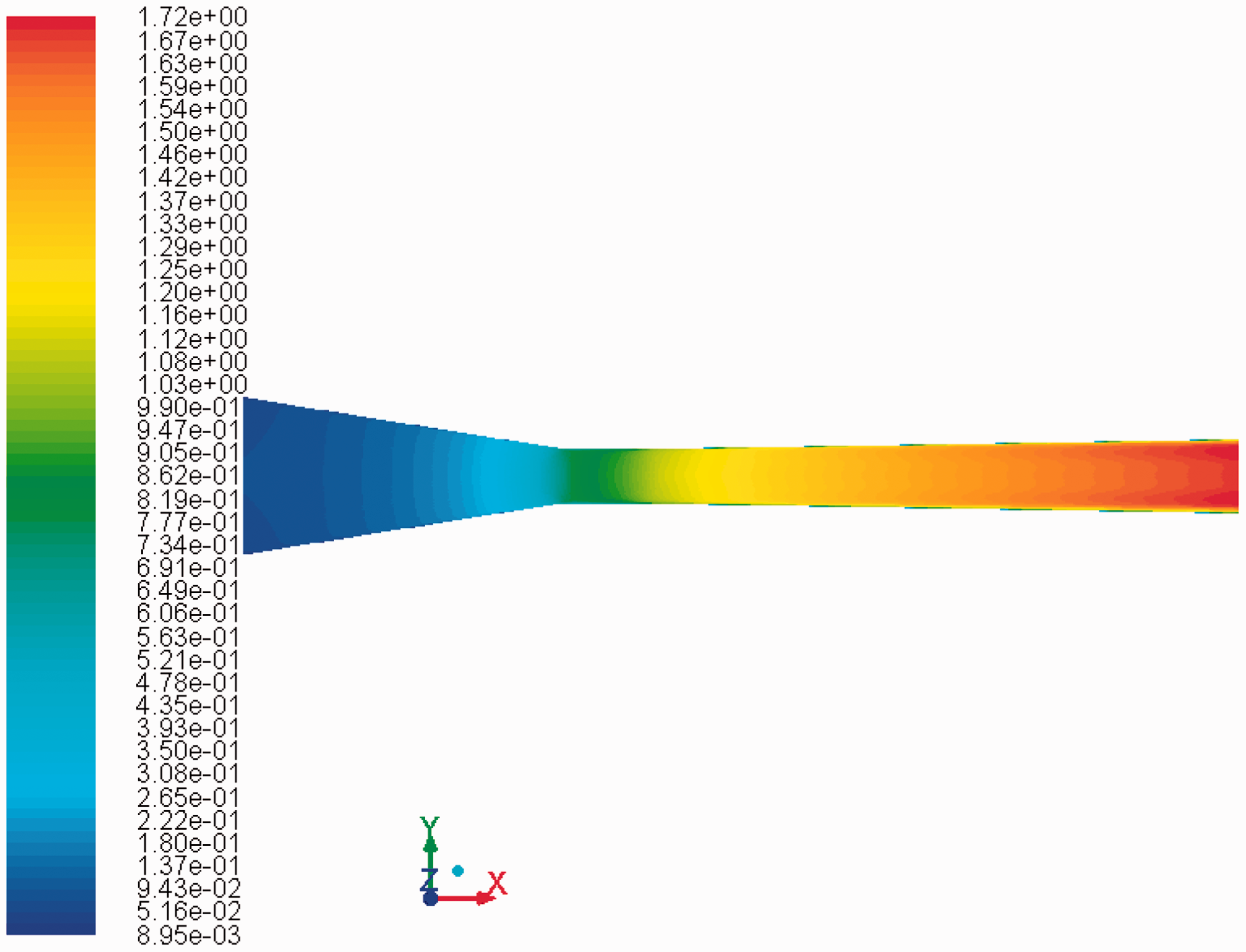
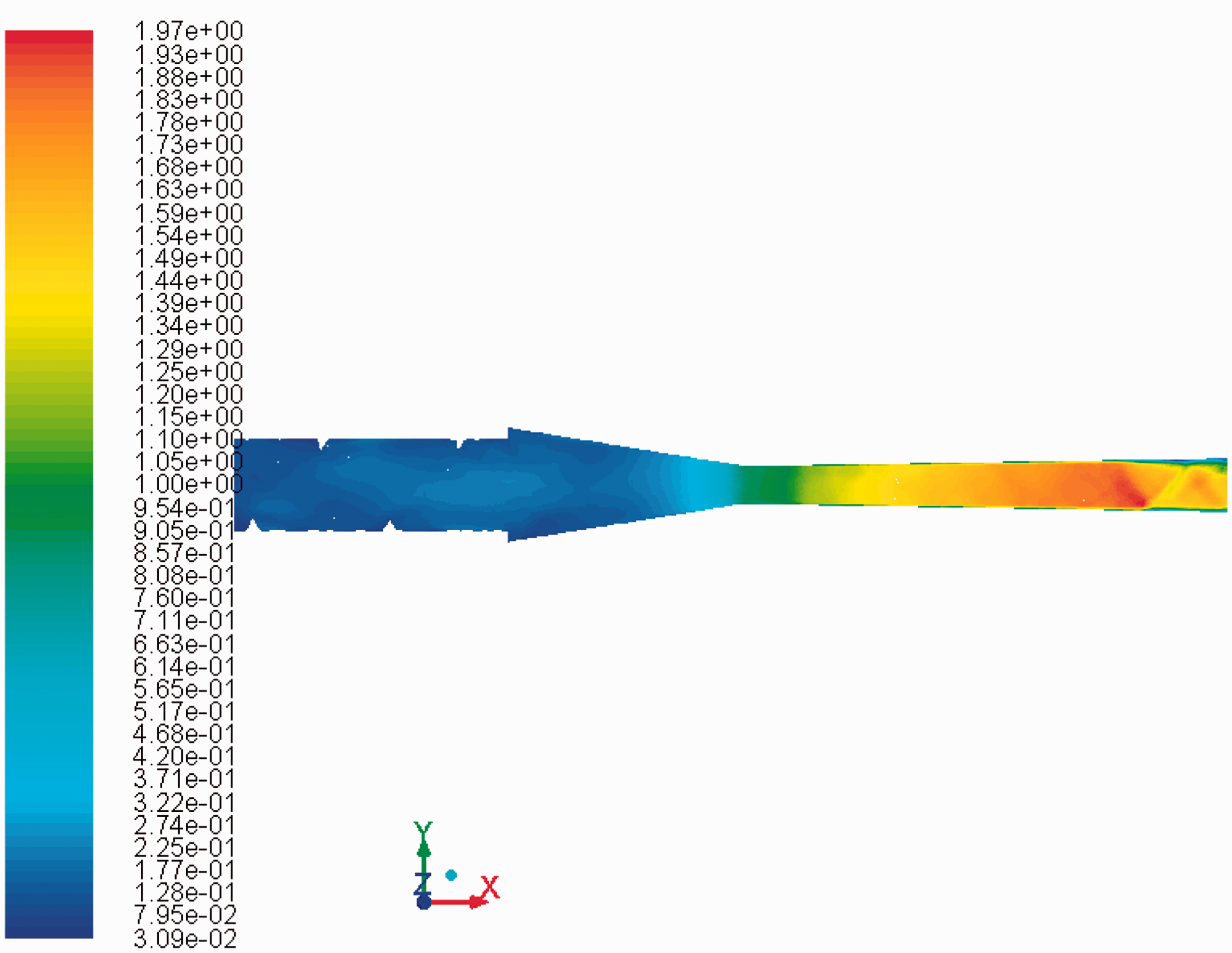
Mach contours of the DPM for the nozzle with helical insert (Figure 17) show similar behaviour to single phase simulations (Figure 18). Same as lower pressures there is not any loss of maximum velocity by injecting particles, which illustrates a great advantage of using swirl flow for abrasive blasting. Although the solver is transient and in single phase simulations showed unsteadiness in the flow, the DPM for the swirl flow does not demonstrate unsteadiness inside the nozzle. This could be because of a reduction on separation zone.
Particle distribution of inlet pressure 4 atm is different to that at lower pressures. For the nozzle without helical insert (Figure 19), unlike lower pressures explained above, particles are distributed more evenly although they are more toward centre of the nozzle. For the nozzle with helical insert (Figure 20), particles are more toward the upper wall up to the first shock wave, and then they are distributed along the outlet as a mixing effect of shock wave.
Particle trace coloured by particle residence time for the nozzle without helical insert at inlet pressure 4 atm. Particle trace coloured by particle residence time for the nozzle with helical insert at inlet pressure 4 atm.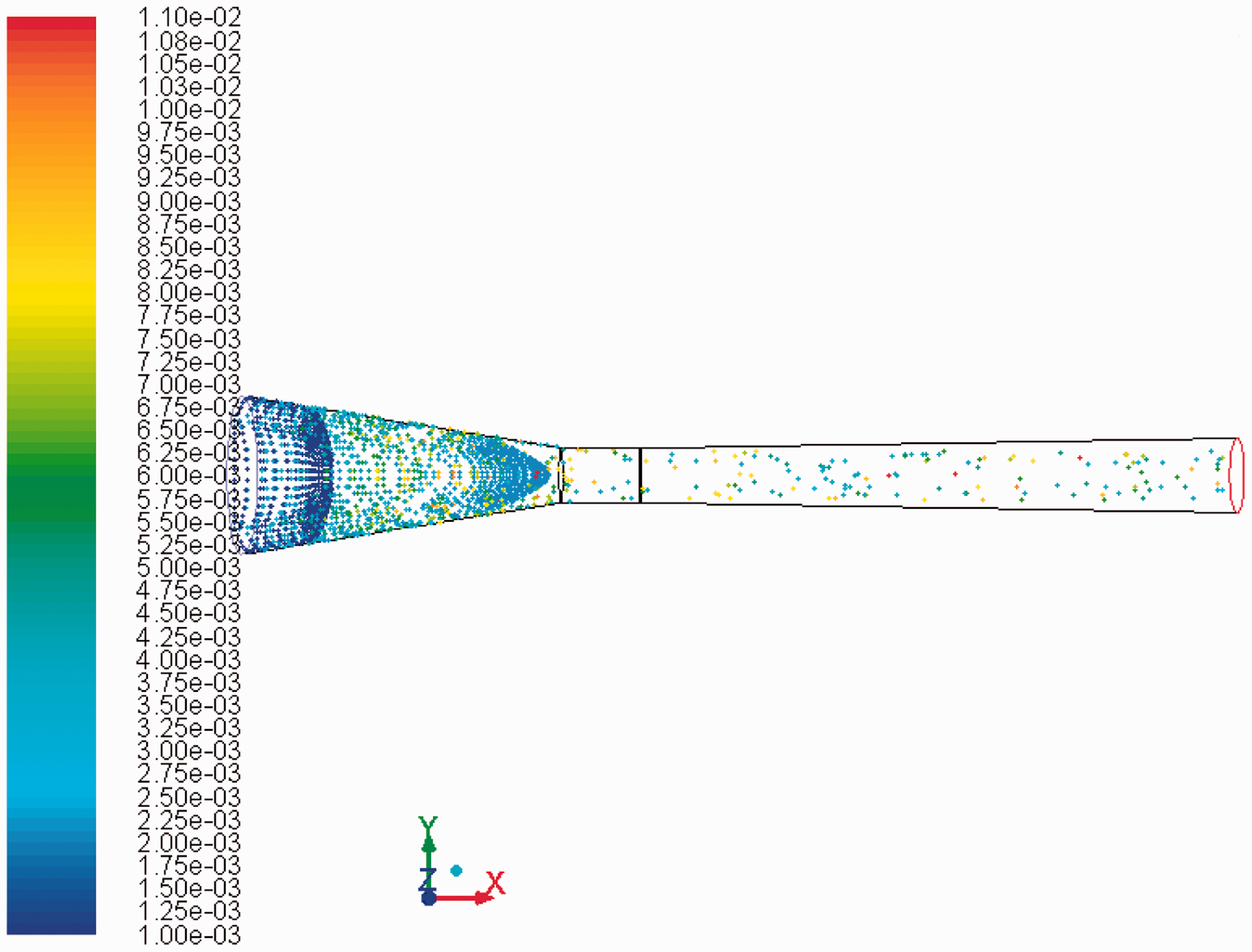
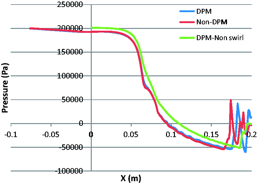
Pressure along the centre line of the nozzle without helical insert (Figure 21) is almost identical to single phase simulation. This shows that the particles have less effect on pressure distribution inside nozzle but they have a major effect on shock wave structure as explained for lower inlet pressures. For the nozzle with helical insert (Figure 22), there is not any major change even in shock structure. Similar to lower pressures, there are small oscillations before the first shock wave in diverging section. Therefore, with the swirl effect, flow parameters will not see a major change between single phase simulations and Lagrangian simulations with particle injection.
Pressure along centre of the nozzle without helical insert for DPM at inlet pressure 4 atm. Pressure along centre of the nozzle with helical insert for DPM at inlet pressure 4 atm.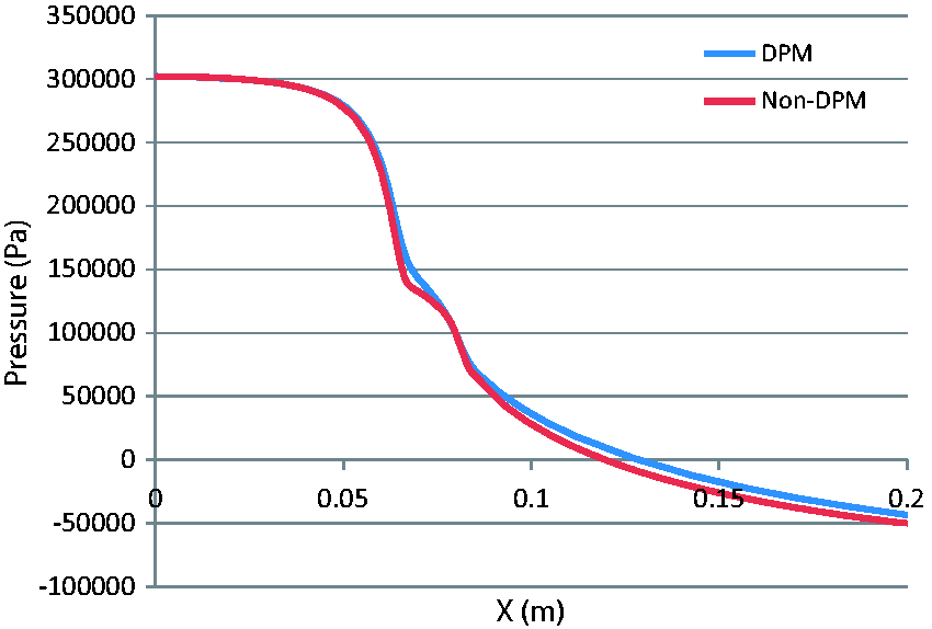
Verification and validation
Grid dependency tests have been conducted on all cases, where extra grid refinement has not changed the results. As mentioned by Ferziger and Perić, 31 it is important for the refinement to be substantial and systematic, as the systematic grid refinement studies are the most reliable and common studies. 32 Systematic refinement means that the grid is refined in all directions with the same ratio. The grid dependency check has been performed by running simulations for 200 k, 320 k and 500 k cells. As the numerical results for cells above 320 k were stable and similar, therefore, all the simulations are based on 320 k cells with special attention in refining the mesh at the exit boundary to capture shock waves.
The maximum wall
Validation is a process to assess numerical modelling uncertainty by using benchmark experimental data, and when it is possible, estimating the sign and magnitude of numerical modelling error. 34 The fundamental strategy for validation is identification of the error and uncertainty in the conceptual model, quantification of the numerical error in the numerical solutions, prediction for experimental uncertainty and finally a comparison between simulation results and experimental data. 35 However, due to the impracticality and the difficulty of performing exact validation experiments on complex systems, recommended method is to use small-scale benchmark experiments. 36
The numerical model was validated by running our model for same simulations of Xiao et al.
37
The Mach number contours for Fluent simulation at area ratio ( Mach number contours at Ae/At = 1.5 and PR = 2.0 for: (a) results by Xiao et al.
37
, and (b) CFD simulation.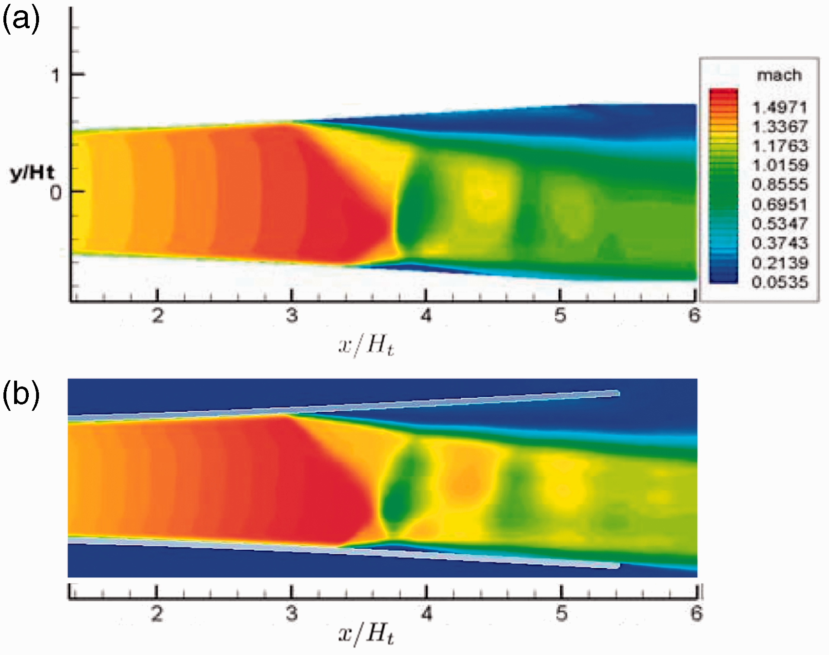
The centre line pressure is compared with experimental test by Abbasalizadeh et al.
38
and Abbasalizadeh.
39
This experimental test was performed on the same nozzle without helical insert. Comparing experimental test with simulations (Figure 24), where both performed at inlet pressure 3 atm, illustrates that there is good agreement between experimental data and numerical results. There is less than 3% error in calculations. This difference could be due to unsteady flow behind shock wave that creates a separation zone.
Static pressure at the centre of nozzle for inlet pressure 3 atm.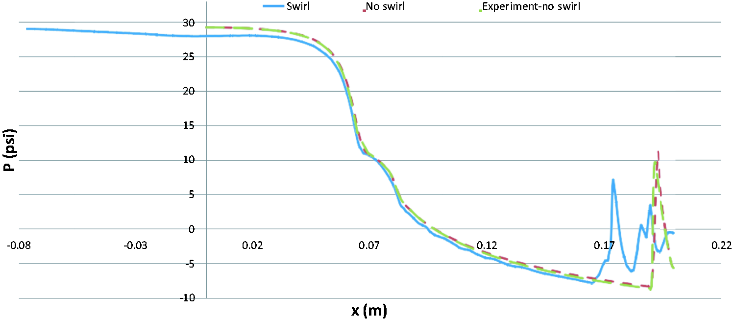
Conclusion
It was shown that Eulerian model is not sophisticated for granular supersonic flow unless there is a large volume fraction of the second phase. DPM results showed that maximum Mach number will be reduced by particles injection in the non-swirl nozzle, however, with swirl effect, there was not a major loss of maximum Mach number. This effect was more influential at lower pressure ratios where the maximum Mach number reduction was 22% at inlet pressure 2 atm and just 8% at inlet pressure 4 atm. Unlike single phase simulations, in Lagrangian approach neither non-swirl nor swirl Mach number contours showed any unsteadiness inside the nozzle. This could be the result of reduction in size of separation zones. In DPM simulations for the nozzle without helical insert, as an effect of particles concentration at the centre of the nozzle, there were major changes on the shock wave structure. On the other hand, in DPM simulations for the nozzle with helical insert there were not any major change on the shock structure as there were better particle distribution inside the nozzle; also swirl flow increases turbulent intensity inside the nozzle.
Footnotes
Declaration of conflicting interests
The author(s) declared no potential conflicts of interest with respect to the research, authorship and/or publication of this article.
Funding
The author(s) received no financial support for the research, authorship and/or publication of this article.