
Abstract
Coverage in unknown environment is a commonly concerned problem in ground mapping field of Unmanned Aerial Vehicle (UAV). Based on the concept of incremental cell construction, a practical online coverage path planning method is proposed for mapping in unknown environments with obstacles and boundaries. This method consists of the Boustrophedon motion and D* algorithm. Based on the information from onboard ranging sensor, the UAV uses Boustrophedon motion to incrementally construct coverage cells while exploring the environment. When there are no alternative cells for Boustrophedon motion, the D* algorithm is utilized to plan the backtracking path to the next starting point. Particularly, the backtracking path replanning will be carried out if an unknown obstacle suddenly appears on the path. The static and hardware-in-loop dynamic simulation results show that the proposed method can achieve near-complete coverage in complex unknown environments with low computational and sensor accuracy requirements.
Introduction
In air-to-ground mapping task, the Unmanned Aerial Vehicle (UAV) equipped with visual sensors such as camera, is used to obtain the interested information by storing or transmitting the mapping images back. With the reduction in drone cost and the improvement in flight performance, the advantages of UAV in ground coverage mapping have been highlighted compared to other platforms such as satellite 1 and manned aircraft. 2 Hence the UAV has become an important technical mean in the fields of fire-fighting and rescue,3,4 persistent surveillance, 5 precision agriculture, 6 and anti-terrorist, 7 etc.
Due to the flight height constraint and limited field of view, a single mapping image is not enough to completely cover the target environment in most mapping applications. The UAV needs to collect a set of target images from different locations and subsequently merge them based on geographic information, to obtain the global information of the target area. Hence the coverage path planning for UAV is to plan a path that traverses the entire area with optimized objectives such as the minimum flight distance, the maximum coverage rate, and conflict-free flight based on the onboard sensors.
Currently, various coverage path planning methods have been proposed for robot and UAV including the trapezoidal decomposition method, 8 the Boustrophedon method,9,10 the Spanning Tree Coverage (STC) method, 11 the virtual potential function based exploration, 12 the reinforcement learning-based coverage path planning algorithm, 13 etc. Most of the existing methods decompose the workspace into obstacle-free cells at first, 14 and then plan the coverage order and path to traverse each cell.
The Boustrophedon method is one of the most practical approaches for coverage problem. Firstly, the Boustrophedon method can efficiently plan the full coverage path by back-and-forth Boustrophedon motions, 15 which can reduce unnecessary turns and repetitive overlays.16,17 Secondly, this method can handle areas with different shapes including convex and concave polygons. At the same time, the algorithm can also consider turning, obstacles and other factors to find the optimal path,18,19 which makes it more adaptable in practical applications. Finally, the priorities and constraints can be easily added into Boustrophedon coverage problem. 20 With the help of its scalability, the Boustrophedon method can adapt more effectively to diverse application scenarios.
However, similar to most of the existing coverage methods, the Boustrophedon method still needs the prior knowledge including the shape of the area to be covered, the detailed information about obstacles, and so on. The path planning usually relays on pre-decomposed cells, which cannot handle unknown environments with boundaries and dynamic obstacles. Therefore, these methods cannot meet the requirements of online coverage path planning for unknown and enclosed environments, such as indoor environments.
Aiming at the ground mapping task in unknown enclosed environments, this paper proposes a practical online coverage method based on the idea of incremental cell construction. The practical Boustrophedon motions are used to gradually explore the workspace and construct the mapping image cells incrementally. After a set of Boustrophedon motions, the D* algorithm is used to planning the backtracking path to the next Boustrophedon starting point. Particularly, the local path replanning is performed for obstacles that suddenly appear on the backtracking path. The coverage simulations of various coverage scenarios and a hardware-in-loop (HIL) dynamic simulation are carried out for performance validation. The simulation results demonstrate that the proposed method can complete the mapping coverage tasks with higher coverage rate, real-time performance and robust adaptability to unknown environments.
Problem statement
The problem concerned in this paper is to plan a flight path consisting of a series of waypoints for UAV ground mapping coverage at a specified altitude. The UAV traverses these points in turn to collect mapping images with high coverage rate and low flight risk. The multi-rotor UAV used in ground mapping has no prior knowledge of the environment to be covered. Its coverage planning only relies on local sensor information. The airborne vision sensor such as camera, is installed in the center of the aircraft, and its lens points downward to collect ground images. The scene of ground mapping is shown in Figure 1.

Scenario of UAV ground mapping.
Assuming that each image on the ground taken by the vision sensor is a square cell with side length of d. The size of the cell covered by the image is proportional to the sensor image size:

Since the UAV usually performs mapping tasks at the optimal flight height determined by equation (1), the environment to be mapped can be simplified as a two-dimensional plane in the Cartesian coordinate system. Thereby the UAV ground mapping task can be transformed into the problem of covering the non-obstacle space with square image cells.
The position of the UAV in the mapping flight plane can be defined as
The UAV detection model is shown in Figure 2. The short-dotted circle denotes the UAV body with radius R. The solid circle is the safe flight area with radius dsafe, and the dashed square is the coverage cell

UAV detection model.
To merge multiple collected images at different locations into a complete mapping image, overlapping parts should be kept between adjacent images. The sufficient overlapping rate not only provides matching feature points for image merge, but also avoids coverage rate decreasing caused by image distortion caused by the position and attitude fluctuates of UAV. If the overlapping rate is r, the distance between two neighbor cells is
Additionally, the multi-rotor UAV used for ground mapping needs to have the capabilities of indoor navigation and autonomous flight. The position control accuracy should meet
Coverage path planning based on incremental cell construction
This section provides a description of the proposed coverage path planning method from a top-level perspective. The flow chart of the method is shown in Figure 3.

Flow chart of the proposed method.
The UAV has no prior knowledge about the environment before flight. At each time step, it chooses the target position in alternative cells based on Boustrophedon motion rules. If the UAV reaches a position without alternative cells, a backtracking point will be selected as the next Boustrophedon starting point. Furthermore, the backtracking planning process including collision-free D* path planning and straightening will be carried out. If unknown obstacles appear on the backtracking path during flight, the UAV will temporarily hover at safe region and execute path replanning. By means of iterative exploration-backtracking process, the unknown environment will be covered by incrementally constructed cells.
Incremental boustrophedon coverage
Boustrophedon motion refers to the path planning method which is similar to the route of cattle plowing in the farm. The UAV crosses the area from one boundary to the opposite one, turns around, and then walks back along the adjacent lane to the starting edge. By repeating this motion, the UAV can cover the expected area.
Aiming at handling the coverage problem in unknown environments, an incremental Boustrophedon motion is designed to decompose the workspace into square cells step by step. This motion is characterized in that the cell is created incrementally with each step of the Boustrophedon motion, rather than creating all the cells at once before the UAV flight. The step length of Boustrophedon is the distance ds between the centers of two neighbor cells. Before each Boustrophedon step, the UAV calculates the safely travel distance dadvance according to the distance measurement by lidar in directions of front, back, left and right. Then the adjacent cells in these four directions will be labeled as uncovered (UC), covered (C), blocked (B), partially blocked (PB), and partially blocked and covered (PBC) according to the conditions shown as follows.
If If If If If
All labels of adjacent cells will be stored and used for backtracking path planning.
The target cell of the next Boustrophedon motion will be selected in adjacent cells labeled as UC or PB, which is called alternative cells. The UAV preferentially selects forward cells, and selects backward cells in second priority. If there are no forward or backward alternative cells, the UAV will select the left-right cell. A random selection is made in the left-right cell selection for the first time, then the direction will be locked. It means that in the following left-right cell selections, the UAV selects cells in the locked direction until there is no alternative cell in this direction. This rule can effectively reduce the number of UAV turns in order to lower the flight consumption.
However, in a particular scenario as shown in Figure 4, the UAV will go forward to arrival P3 after its obstacle avoidance according to the basic Boustrophedon motion selection rules. This decision will leave a part of the uncovered region behind P2, as the box shown in the left part of Figure 4. This uncovered region needs another set of Boustrophedon motion to cover, which may increase the coverage cost. In this paper, an improvement of Boustrophedon motion is designed with the next-step cell selection rules shown as follows.
The forward alternative cell will be selected, if any of the following conditions are fulfilled:
This is the first time to perform cell selection. The forward alternative cell exists after the left-right selection, and the backward cell is chosen in the last forward-backward cell selection. The alternative cell exists in forward but not backward direction. The backward alternative cell will be selected, if any of the following conditions are met:
The backward alternative cell exists after the left-right cell selection, and the forward cell is chosen in last forward-backward cell selection. The alternative cell exists in backward but not forward direction. The left alternative cell will be selected, if the forward or backward alternative cells do not exist and any of the following conditions are fulfilled:
This is the first time to perform left-right cell selection, and the random selection favors the left. There is no right-oriented alternative cell. The left orientation was selected in the last left-right cell selection. The right alternative cell will be selected, if forward or backward alternative cells do not exist and any of the following conditions hold true:
This is the first time to perform left-right cell selection, and the random selection favors the right. There is no left-oriented alternative cell. The right orientation was selected in the last left-right cell selection.
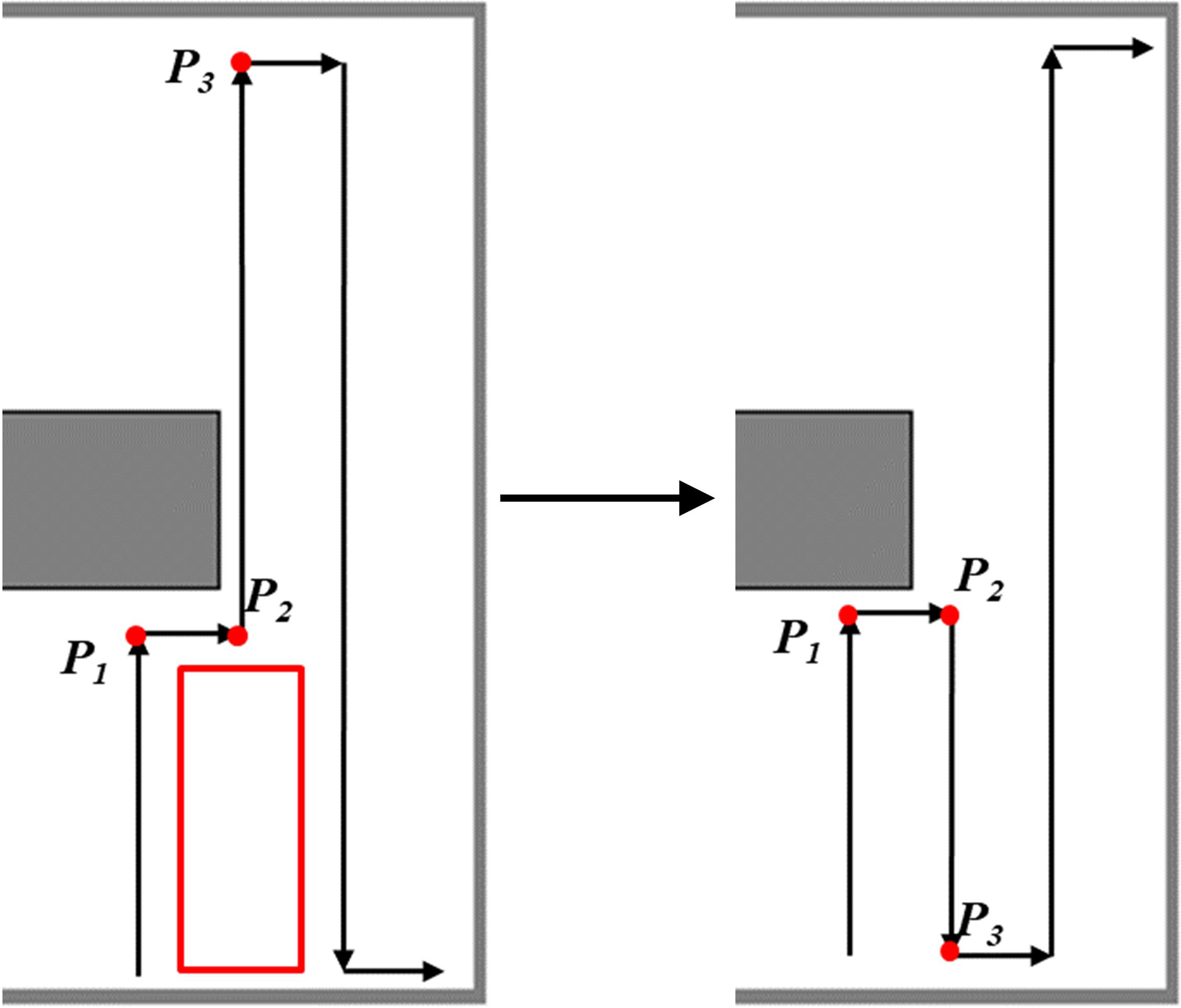
Boustrophedon motion improvement.
The effect of the improved Boustrophedon motion is shown in the right part of Figure 4. The UAV chooses to travel backward after arriving at P2 despite the existence of alternative cells in the forward direction. This improvement can deal with obstacle avoidance appropriately, which will not leave uncovered region.
After the target cell is selected, the UAV flies from cell i to cell i + 1. If UAV moves forward by step length ds, the cell i + 1 will be marked as C. If cell i + 1 has been marked as PB, or an obstacle suddenly encounters during the flight, the cell i + 1 will be marked as PBC.
The UAV repeatedly performs the improved Boustrophedon motion until it reaches the position without any alternative cell, which represents the end of a set of Boustrophedon motion. The coverage effect in a simple closed environment is shown in Figure 5. Then the backtracking path will be planned to approach the starting point of the next Boustrophedon motion.
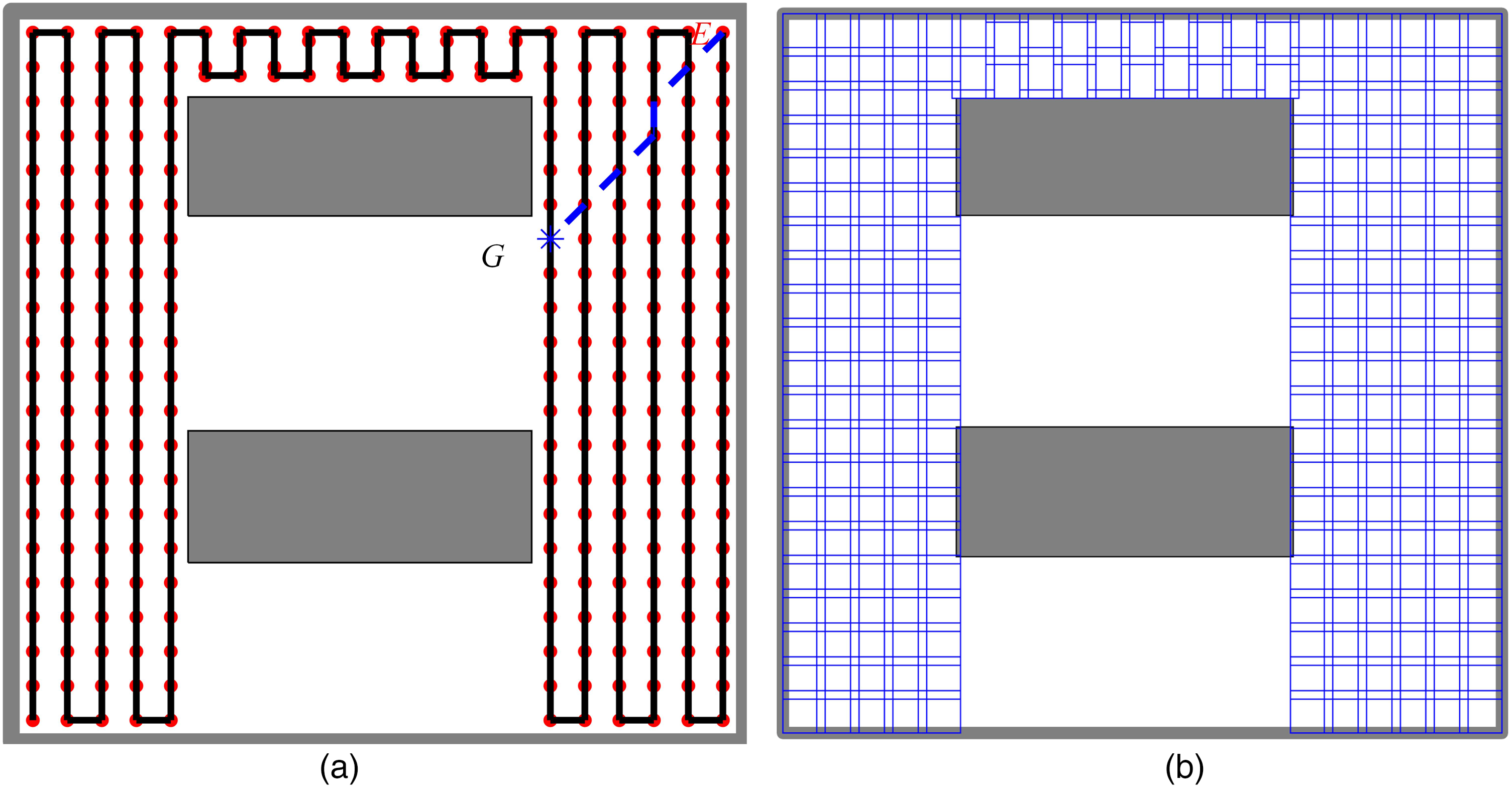
Coverage of a set of boustrophedon motions: (a) centers of cells and UAV routes; and (b) covered area.
Backtracking path planning
Most coverage applications cannot be covered by a simple set of Boustrophedon motions. If the UAV reaches a cell without alternative cell options, it needs to perform backtracking planning. In this method, a new starting point for the next set of Boustrophedon motions will be selected in the cells already constructed and labeled with C or PBC, and a collision-free path will be planned from the current position to the new starting point. The backtracking path planning consists of the following four steps.
1. Recorded cells preprocessing 2. Backtracking point selection
The algorithm checks all the neighbor cells already constructed and marked with UC or PB. If the neighbor cells have already been covered by Boustrophedon motions, their labels are renewed to C or PBC.
For the sake of reachability and safety, only covered locations

For the Boustrophedon motions end with point E in Figure 5(a), point G is selected as the backtracking point to start the next Boustrophedon coverage.
3. Backtracking path planning
As the backtracking point bas been covered previously, its reachability can be assured. The simplest backtracking path is to return to this point along the previously generated Boustrophedon path, but this path leads to greater flight consumption. Therefore, it is necessary to search for an optimized collision-free path from the current position to the backtracking point. This path only goes through the covered cells to avoid the flight risk in unknown environments. Thus, the backtracking path planning problem can be condensed into finding the shortest path within the network topology.
D* (Dynamic A*) algorithm is one of the most commonly used algorithms for solving the shortest path problem. This algorithm firstly establishes distance potential field from each possible location to the destination to obtain the initial optimal path. Then, the UAV goes towards the destination along the path. If dynamic obstacles are encountered, the map and path cost will be updated and the path will be replanned. D* algorithm not only ensures the optimization of the path, but also has strong adaptability to complex unknown environments.
In this paper, D* algorithm is adopted for backtracking path planning. The search space
Each backtracking position in the environment can be represented as a node
In the cost calculation of backtracking path, both the minimum path cost and flight safety should be considered. The cost function from position Pfi to Pfj is defined as

The D* algorithm establishes three tables identified as NEW, OPEN and CLOSED respectively. Initially, all nodes are placed in NEW table. Subsequently, every node will be moved to OPEN table for further handling. Nodes in the OPEN table represent potential candidates for the shortest path and are prioritized based on their estimated cost to the target node. If a node is successfully reached at the target or determined to be unreachable, it will be placed in the CLOSED table, indicating that its processing is complete. The D* algorithm maintains the OPEN and CLOSED tables through the PROCESS-STATE and MODIFY-COST steps. At the beginning, the backtracking point G is placed in the OPEN table. The PROCESS-STATE module is repeatedly executed until the current position of UAV is removed from the OPEN table or the OPEN table is empty. Then the complete path to the backtracking point is linked by the backward pointers of each node. The MODIFY-COST module is responsible for changing the cost function 4. Backtracking Path Straightening
The backtracking path shown in Figure 5(a) contains 7 center points of cells including the starting point E and the target point G. The zigzag path is turning-intensive, which does not fit for UAV flight. Therefore, it is necessary to perform straightening optimization on the planning results of the D* algorithm. Unlike the obstacle-free straightening method in existing literatures, the UAV cannot be regarded as a point mass, and its flight path should not only be obstacle-free but also maintain a safe distance from known obstacles.
Considering three points U, V, and W on the UAV path as shown in Figure 6(a), the notation


Optimization of backtracking path: (a) backtracking path straightening algorithm; and (b) straightened backtracking path.
The path shown in Figure 5(a) is straightened and optimized into a line connecting the starting point and the target backtracking point, as shown in Figure 6(b). The path has no turns and its length gets 4% reduction compared to the original path, which is beneficial for the flight of the UAV.
After path straightening, the backtracking path to the starting point of the next set of Boustrophedon motions can be executed by the UAV.
Replanning of backtracking path
If unknown obstacles suddenly appear on the backtracking path, the flight safety and task reliability of the UAV cannot be guaranteed. To monitor flight safety, the UAV examines the surrounding distance data measured by onboard lidar while flying along the backtracking path. If the obstacles enter the safe flight radius dsafe, the UAV will switch to the hovering state and confirm the presence of obstacles. Then, the center of closest covered cells Pfi along the safe flight direction is selected as the safe parking point. Once the UAV arrives at this safe position, the path replanning will be conducted.
In path replanning process, MODIFY-COST is used to modify the neighbor labels of each cell in the workspace
After updating the consumption from each cell to the backtracking point G, PROCESS-STATE is executed repeatedly to generate a new backtracking path, and the UAV will continue to move towards the backtracking point along the new optimized path. As shown in Figure 7, when the UAV travels along the path EG and reaches point W, a dynamic obstacle marked by dashed lines appears on the backtracking path. The UAV switches flight mode to hover immediately, and selects the nearest reachable cell center U. Then path replanning and straightening optimization are adopted, and the UAV follows the new path to reach point G for performing the next set of Boustrophedon motions.

Path replanning in case of dynamic obstacles.
The Boustrophedon motion and backtracking will be iteratively performed until all cells in
Simulations and analysis
To the best of our knowledge, there is currently no benchmark for the coverage problem of drones in unknown environments. Hence it is important to design convictive simulations to evaluate the performance of the proposed method. This paper presents two parts of simulation results. At first, a set of different environment models are adopted to test and verify the coverage performance. Furthermore, a hardware-in-loop (HIL) simulation system was built with the low-cost embedded system, a quad-rotor UAV dynamic model and a typical 3D urban mapping scenario. A HIL simulation is carried out to illustrate the real-world applicability of the proposed method.
Coverage performance validation and analysis
In coverage performance simulations, the safe flying distance of UAV dsafe = 0.4 m, the radius of UAV is 0.15 m, the side length of mapping image d = 3 m at a certain flying height, the image overlapping rate r = 20%, and the effective range of the onboard distance sensor lr = 5 m. The UAV has no prior knowledge about the environment and plans the coverage path relying only on the information of local sensors. The simulation is designed and completed on a computer with a 2.6 GHz Core i5-3230 M and 4GB RAM. Additionally, the same simulations are performed by online spanning tree coverage (STC) for comparison.
1. Coverage in simple environment
Firstly, the simple environment shown in Figure 5 is covered. The generated flight path and coverage effect are respectively shown in Figure 8(a) and (b). Three sets of Boustrophedon motions are performed, and the image cells achieve complete coverage of the obstacle-free space.

Coverage effect of simple environment: (a) image capture position and path; and (b) space covered by image cells.
The path and coverage effect based on STC method are shown in Figure 9(a) and (b). The decomposed cell length is d = 2.4 m. 85.61% of obstacle-free space is covered.
2. Coverage in non-convex polygonal obstacle environment
Coverage effect of simple environment based on STC: (a) image capture position and path; and (b) space covered by image cells.
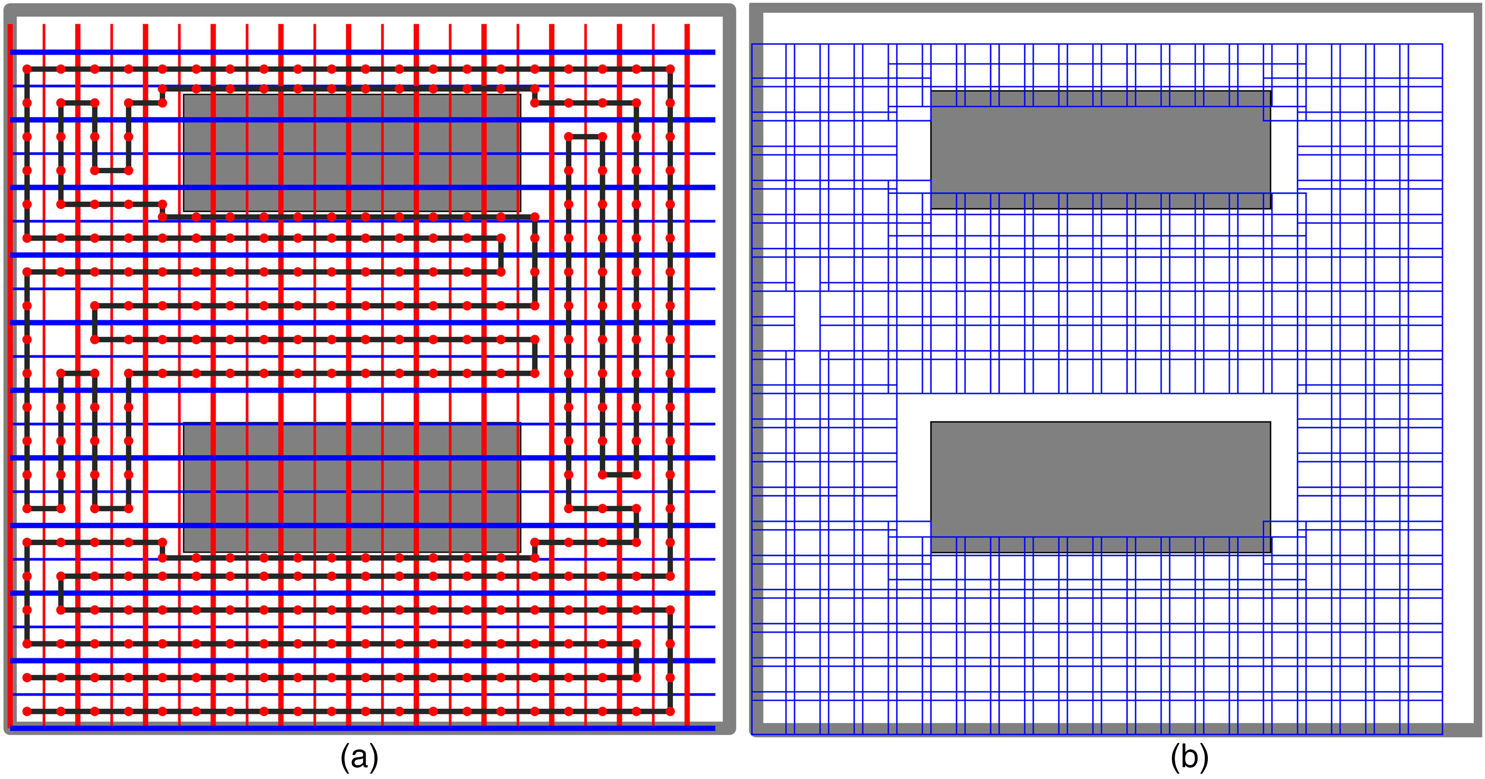
The coverage for the environment with non-convex polygonal obstacle is shown in Figure 10(a) and (b), where the sides of obstacles are not parallel to the flight direction. Three one-step Boustrophedon motions are used to fill in the uncovered areas along the bevel edge after the second set of coverage motions. Seven Boustrophedon motions are executed in total, and a coverage rate of 99.96% is achieved.

Coverage effect of non-convex polygonal obstacle environment: (a) image capture position and path; and (b) space covered by image cells.
The path of UAV and coverage effect based on STC method are shown in Figure 11(a) and (b). 89.17% of obstacle-free space is covered.
3. Coverage in non-convex environment with non-convex polygonal obstacles

Coverage effect of non-convex polygonal obstacle environment based on STC: (a) image capture position and path; and (b) space covered by image cells.
For the complex non-convex environment with non-convex polygonal obstacles, the coverage effect is shown in Figure 12(a) and (b). Eight Boustrophedon motions were executed, and the UAV mapping cells cover the non-obstacle space completely.

Coverage effect of non-convex environment with non-convex polygonal obstacles: (a) image capture position and path; and (b) space covered by image cells.
The path of UAV and coverage effect based on STC method are shown in Figure 13(a) and (b). 85.11% of obstacle-free space is covered.
4. Coverage in complex irregular-polygonal obstacle environment

Coverage effect of non-convex environment with non-convex polygonal obstacle based on STC: (a) image capture position and path; and (b) space covered by image cells.
To validate the applicability of the proposed method in complex polygonal area coverage, the non-convex polygonal environment with a non-convex polygonal obstacle is designed. The coverage effect is shown in Figure 14(a) and (b). As the sides of area and obstacle are not parallel to the flight direction, more Boustrophedon motions are consumed in coverage, and 99.90% of the non-obstacle workspace is filled.
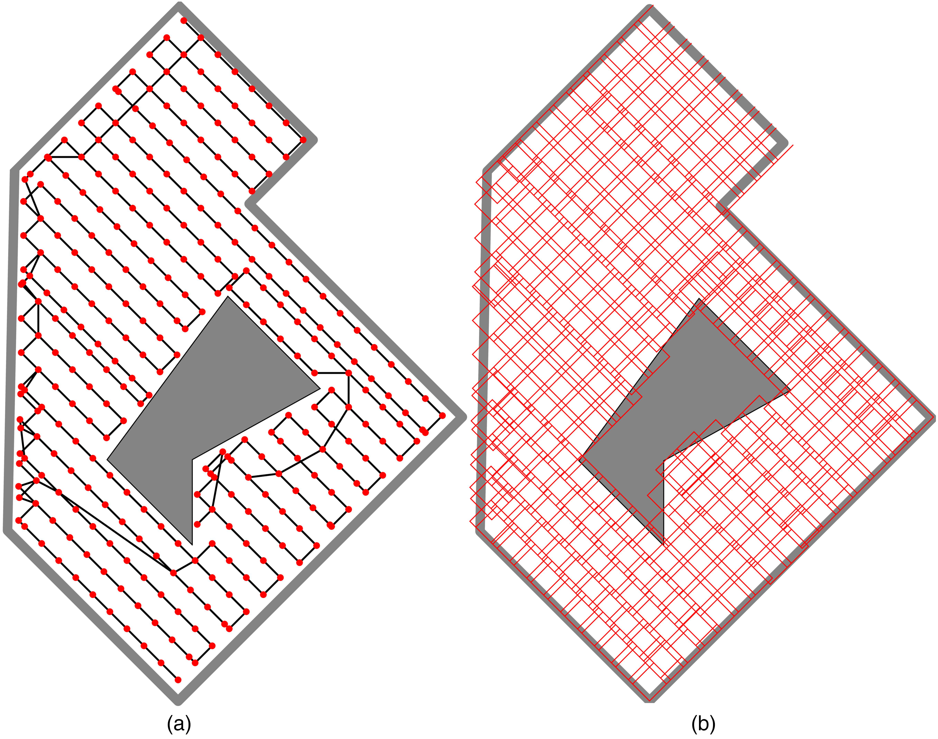
Coverage effect of complex irregular-polygonal obstacle environment: (a) image capture position and path; and (b) space covered by image cells.
The path of UAV and coverage effect based on STC method are shown in Figure 15(a) and (b). 94.08% of obstacle-free space is covered.
5. Performance comparison

Coverage effect of complex irregular-polygonal obstacle environment based on STC: (a) image capture positional and path; and (b) space covered by image cells.
The performance comparison results between the proposed method and STC are shown in Table 1.
Coverage performance comparison.
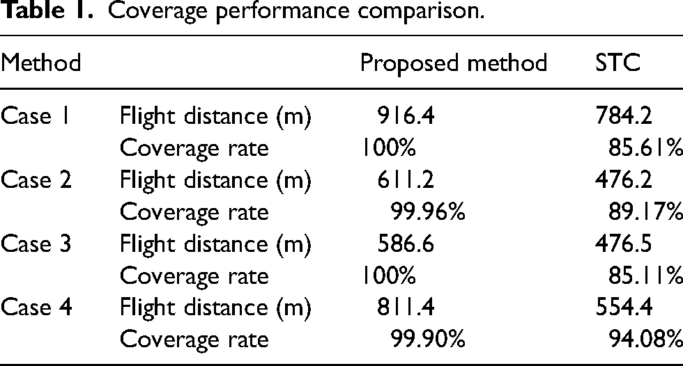
The online STC method is also designed for unknown environment coverage tasks and relies only on local information. However, the generation tree based on a fixed cell side length of 2d results in rough spatial decomposition, which has poor adaptability to unknown environments. Additionally, it may fail to cover the cells with a large proportion of obstacles, ultimately resulting in a low coverage rate. In the incremental coverage method proposed in this paper, the coverage cells are not decomposed with fixed position, but dynamically constructed within the environment exploration process. This method significantly enhances the ability to cover partially blocked cells and increases the coverage rate in unknown environments. The path length increasement is within tolerance.
HIL simulation of mapping in urban environment
To make the simulation have a definite practical meaning, a challenging HIL simulation is carried out where a quad-rotor UAV performs a complex ground mapping task. The goal of the UAV is to collect mapping images by incremental coverage path planning, and then merge the images to get a general downward view of the urban environment.
The architecture of the HIL system is shown as Figure 16. The proposed coverage path planning area runs in a low-cost embedded system based on STM32F407 micro control unit. The other algorithms related to the mapping task are all configured in the simulation computer, including environment sensing by lidar, navigation, flight control, mapping image collection, UAV dynamics and the urban environment model. In order to obtain the real UAV dynamics in mapping, the kinematics and dynamics model of quad-rotor published in reference 21 is taken into consideration. The communication between the embedded system and simulation computer is achieved by Universal Asynchronous Receiver/Transmitter (UART).

Architecture of the HIL simulation system.
According to the lidar detection data and flight parameters provided by simulation computer, the coverage path planner makes the real-time decision of the next-step target waypoint, and sends it to computer. The flight controller guides the dynamic UAV model flying in simulated urban environment. When the UAV arrives at the waypoint, the 24 surrounding distance points will be measured and send back, and the mapping image will be captured and saved in memory.
To make the simulation results more visualized, a visualized 3D urban scenario with a quad-rotor UAV is designed by the Virtual and Reality Toolbox of MATLAB as Figure 17. The side length of observation image d = 6 m at the flight height of 20 m. In this height, five buildings marked in Figure 17 can be detected as obstacles by onboard lidar. For ease of simulation data generation, these buildings are simply represented by three rectangles and two cylinders. In this scenario, the virtual world can be extracted by a downward simulated camera attached with UAV, and the images will be merged into a complete image of the scenario after the coverage task. A video of this simulation is provided as the attachment to this paper.

The visualized 3D urban scenario.
During this simulation, the proposed method works well on STM32 embedded system, the average execution time of Boustrophedon motion and backtracking path planning is less than 20 ms and 470 ms respectively. The coverage for the environment in urban area is shown in Figure 18(a) and (b). The UAV collects image at each point safely and achieves a coverage rate of 99.98%. 422 mapping images are collected in total.

Coverage effect of urban area: (a) image capture position and path; and (b) space covered by image cells.
At last, all the collected 422 ground mapping images are merged into a whole image of urban area, as shown in Figure 19. The white area in this figure is not covered by the images, which is the horizontal projection of the five buildings in Figure 17. The names of buildings are marked in the white obstacle areas respectively. Only 3 tiny areas around the central cylinder building are missed, while the near-completely information about the urban area is obtained by the coverage flight without any prior knowledge. In this HIL dynamic simulation, the real-time performance, low-cost hardware compatibility, real-time data processing and decision-making capabilities of the proposed method are fully validated. The simulation results show that the proposed method is practical and real-world applicable in unknown complex environments.

Photo merge result of the whole urban area.
Conclusion
This paper presents a practical online coverage path planning method based on Boustrophedon motions and D* algorithm for UAV ground mapping tasks in unknown environments. The coverage cells are constructed by simple Boustrophedon motions step by step, and D* algorithm is used to plan the safety path to link up several sets of Boustrophedon motions. Based on this method, the UAV obtains the ability of performing the coverage task solely on local sensor data in real-world applications.
The advantages of this method are four-fold:
Low requirements for environment sensing and modeling. This method does not require accurate measurement of environments and obstacle boundaries within coverage process. Instead, the labels of neighbor cells are used to record the surrounding environmental information, which significantly reduces sensor accuracy requirements. High availability in complex unknown environments. This method does not require any prior knowledge of the environment to be mapped, and relies only on local sensor information to perform the coverage task. It fits for the UAV to execute online mapping tasks in unknown environments. Furthermore, this method can handle multiple complex environments including non-convex mapping areas and complex obstacles. Low complexity and high real-time performance. The proposed method reduces the computational load by efficient detection information processing and real-time decision algorithms. The low-cost embedded system can meet its resource requirements. This is a significantly feature for practical online flight applications. Enhanced flight safety and adaptability to uncertainties. Unknown environments are often dynamic and full of uncertainties. After completing a set of Boustrophedon motions, the backtracking point is selected in explored cells to reduce the flight risk caused by environmental uncertainties. During backtracking process, the UAV makes environment detection and dynamic obstacle supervision in real time. After unknown obstacles are found, D* algorithm is used for path replanning to ensure flight safety.
For further applications, the proposed method still has some potential limitations. At first, the advantages of this method can be full taken in a large-scale workspace, in which the boundaries of area and obstacles should be several times the side length of a mapping image cell. Its coverage ability in narrow environment is not significantly superior compared with other algorithms. Secondly, in order to lower the algorithm complexity, the proposed method does not consider the obstacle boundary fitting and estimation according to the lidar data. Therefore, more series of Boustrophedon motions will be consumed if the obstacle boundaries are not perpendicular or parallel to the Boustrophedon travel orientation, even though the total path length does not increase too much.
In our future work, the low-cost obstacle boundary detection will be developed based on low-cost lidar sensor. On this basis, the rotation of image cells will be added to cover the obstacles with complex edges, which may be helpful to improve coverage rate and reduce the number of Boustrophedon motions executed. Additionally, more extensive tests and flight experiments will be carried out to make validation with higher practical confidence.
Supplemental Material
Supplemental Material
sj-docx-1-mav-10.1177_17568293241262323 - Supplemental material for Incremental coverage path planning method for UAV ground mapping in unknown area
Supplemental material, sj-docx-1-mav-10.1177_17568293241262323 for Incremental coverage path planning method for UAV ground mapping in unknown area by Zuqiang Yang, Yi Yang, Xingxiu He and Weicheng Qi in International Journal of Micro Air Vehicles
Footnotes
Declaration of conflicting interests
The author(s) declared no potential conflicts of interest with respect to the research, authorship, and/or publication of this article.
Funding
The author(s) disclosed receipt of the following financial support for the research, authorship, and/or publication of this article: This work was supported by the Aeronautical Science Foundation of China, (grant number 20220007004001).
Supplemental material
Supplemental material for this article is available online.
References
Supplementary Material
Please find the following supplemental material available below.
For Open Access articles published under a Creative Commons License, all supplemental material carries the same license as the article it is associated with.
For non-Open Access articles published, all supplemental material carries a non-exclusive license, and permission requests for re-use of supplemental material or any part of supplemental material shall be sent directly to the copyright owner as specified in the copyright notice associated with the article.