
Abstract
This paper describes the development and flight testing of a tail-sitter unmanned aerial vehicle (UAV) platform that has the potential to be tube-launched. Integrated with vertical take-off and landing (VTOL) capability, the platform can perform high-endurance loiter tasks along with low-speed and hovering flights, and land vertically in limited spaces. The current design utilizes a thrust-vectored counter-rotating coaxial propeller combined with a foldable conventional fixed-wing to accomplish both vertical and horizontal flights. A feedback control strategy capable of stabilizing and controlling the vehicle in both vertical and horizontal flight was designed and implemented on a custom-designed 1.7-gram autopilot. Several tests were conducted in hover and edgewise flight with aggressive pilot inputs to demonstrate the controllability of the aircraft even in the presence of moderate wind gusts. Additionally, transition flight tests were also performed, which demonstrated the vehicle’s capability of transitioning from vertical to fixed-wing horizontal flight using thrust-vectoring-based pitch control.
Keywords
Introduction
Group-1 Unmanned Aerial Vehicles (UAVs with gross weight < 20 lb.) have been widely used in applications including search, rescue, mapping/surveying, and target acquisition (TA). However, limited by the low aerodynamic efficiency at low Reynolds numbers and low energy density of current battery technology, the altitude, endurance, and range of these small-scale all-electric UAVs are significantly lower when compared to their large-scale counterparts.1,2 Tube-launching is currently being explored as a deployment method not only to increase the range of these energy-constrained systems but also to improve the versatility of operation of UAVs and broaden their applications.3,4 With tube-launch capability, UAVs could be launched from a wide variety of platforms, including moving ground vehicles, aircraft, helicopters, ships, and even surfaced submarines, significantly increasing their applications.
There are two types of tube-launched aircraft: rotary-wing aircraft and fixed-wing aircraft. The rotary-wing aircraft are adept at missions requiring hovering capability, such as real-time video streaming focused on a fixed target. Currently, only a few rotary-wing tube-launched UAVs have been developed. Many existing platforms, such as the tube-launched Streamlined Quick Unfolding Investigation Drone (SQUID) developed by the Jet Propulsion Laboratory (JPL) at California Institution of Technology, the thrust-vectoring coaxial-propeller-based gun launched MAV (GLMAV) developed by Texas A&M University, and the GLMAV developed by French-German Research Institute of Saint-Louis (ISL), are still in the early stages of development.4–6 On the other hand, some tube-launched fixed-wing platforms, such as AeroVironment’s Switch Blade and AREA-I’s ALTIUS-500, have been used in military applications.7,8 Compared to rotary wings, these fixed-wing platforms generally have significantly higher endurance. 9 Since fixed-wing UAVs require some forward speed for generating lift, it has limited potential to track targets on the ground, especially at the lower altitudes where these vehicles typically operate. In addition, unlike rotary-wing platforms, the current tube-launched fixed-wing UAVs require an open space for landing or specialized infrastructure for retrieval.
In the present work, the vertical take-off and landing (VTOL) capability is combined with the forward flight efficiency of a fixed-wing aircraft to develop the tube-launch capable tail-sitter UAV. The proposed aircraft, once fully developed, can be launched from a wide range of platforms, quickly arrive at the target location via the projectile phase, perform long-endurance loiter tasks like fixed-wing aircraft, and perform low-speed and hovering flights similar to rotary-wing aircraft. After the mission, the aircraft is also capable of landing vertically and being retrieved in a limited space owing to its foldable wings. The flight profile for such a tube-launched tail-sitter UAV is described in Figure 1.
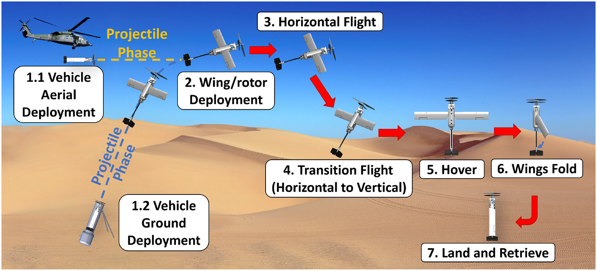
Tube-launched foldable VTOL tail-sitter UAV concept: flight profile.
There are a few technical challenges that need to be overcome to realize this UAV platform, which are: (1) incorporate lifting propellers and foldable wing mechanisms into a compact aircraft that can fit inside a small launch tube, (2) develop a compact yaw-torque-balanced vertical flight configuration that is capable of handling wind-gust disturbances, (3) optimize the efficiency and balance the centre of gravity location for stability in both vertical and horizontal flight, (4) develop control strategies to actively stabilize the platform in vertical, horizontal, and transition flights, and (5) develop systems that can withstand the high accelerations during launch.
The current study focuses on the first four challenges, which had to be overcome to develop a tail-sitter UAV that could potentially be launched from a tube. The design of this aircraft can be divided into two parts: vertical flight design and axial horizontal flight design. The present paper covers the various aspects of these two parts of the design through the different stages of vehicle development.
Early iterations
During the early stages of the design, a series of tail-sitter UAV prototypes were built and flight-tested to test the viability of using single/coaxial propellers along with rotatable active fins for control in vertical flight. Those designs were iterated through the variations in active fin design, including changing the fin’s vertical location relative to the propeller, adding stator vanes to counteract the yaw moment from a single propeller, and using a coaxial propeller. In addition to the design concept and mechanism of the active fin design, the flight performance of each major iteration is also described in this section.
Design concept
One of the primary motivations for using active pitch fins for vertical flight control was because they could be double-purposed as active control surfaces for horizontal flight as well. The active fin concept, where the pitch angle of each fin is actively controlled using separate servo actuators, is shown in Figure 2.
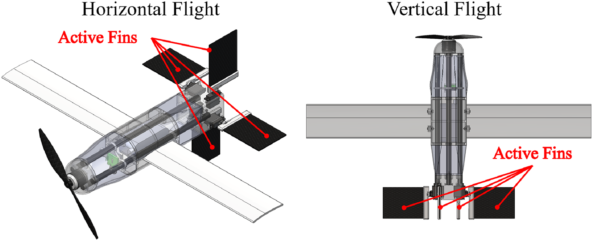
Active fin concept.
As shown in Figure 2, there are four fins (control surfaces) inside the wake of the propeller, which generates control moments in vertical flight. A feedback control system (described in detail in VEHICLE AVIONIC SYSTEMS AND FLIGHT CONTROLS section) was implemented to actively control these fins to stabilize the aircraft in hovering flight. As shown in Figure 3, by placing a fin inside the wake of the propeller with some relative angle of attack

Active pitch fin producing control moment in the propeller wake.
Design iterations and flight test performance
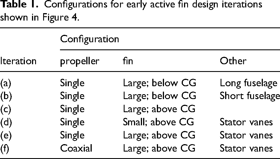
The designs shown in Figure 4 and Table 1 are six major iterations using active fin design. The iteration started with a single propeller on the top combined with a set of four large active fins placed at the bottom of the fuselage, as shown in Figure 4 (a). With large fin pitch angles required for counteracting the steady yaw torque from the single propeller, this configuration lacked control authority for fixed-point hovering even during indoor flights. For iteration (b), the fuselage was significantly shortened to bring the fins closer to the propeller. Stable indoor hovering flight was achieved by this design. However, the control authority was poor. The design was found to be susceptible to even mild gusts and, therefore, was not able to stabilize itself outdoors. To improve the control authority, for iteration (c), the control fins were moved right beneath the propeller, which ensures that most of the fin is within the propeller wake. This design achieved controllable outdoor hovering flight in calm weather conditions but was unable to maintain attitude and position in 10-knot wind gusts. Moreover, an inconsistency in yaw directional control was observed during flight tests. The vehicle tends to yaw more easily in one direction than in the other. This is caused by the fact that all the control fins consistently pitch to one side by a large angle to generate a steady yawing moment to counteract the torque from the single propeller. Because of this, the stall margins of the fins are significantly lower in the direction that the fins are already rotated, causing dissimilar forces when they are rotated in the clockwise versus anticlockwise directions. In design iterations (d) and (e), a set of four fixed stator vanes were installed inside the propeller wake to counteract the steady yaw torque from the propeller. The pitch angle of those stator vanes is adjusted so that the active fins are unloaded and can stay nearly vertical in hover. While both designs use anti-torque stator vanes, small control fins (half the original size) are used in iteration (d) to decrease the susceptibility of the platform to gusts caused by the large surface area of those fins. While both iterations achieved controlled indoor flight, neither of them was able to achieve robust outdoor flight in the presence of moderate gusts. However, from the flight tests, it was observed that the asymmetry in yaw control was improved with the installation of fixed anti-torque stator vanes. However, the aircraft still struggled to hold heading in gusts. A coaxial propeller was then introduced in iteration (f) to balance the yaw torque and improve the yaw control authority. Instead of controlling the yaw by tilting the control fins, the yawing moment was achieved by differential rotational speed control of the upper and lower propellers. In this case, the yaw control input would not interfere with the control margin (stall margin for active fins) for roll and pitch. From flight testing, the control authority of even this design was still limited, yielding the conclusion that the idea of open control fins is not an effective means of controlling and stabilizing a VTOL UAV in the presence of moderate wind gusts. The flight test video compilation of all the above-mentioned design iterations is provided in Ref. 10

Early iterations of UAV using active fin design for hover control.
Configurations for early active fin design iterations shown in Figure 4.
Note that a modular design approach was adopted, which allowed for quickly iterating through different positions of active fins relative to the propeller. Using a combination of carbon fibre tubes and 3D-printed components with similar cross-section interface, the components can simply slide along the fuselage longitudinal axis about the carbon fibre tubes as shown in Figure 5.

Simple modular design layout for active pitch fin design iterations.
As mentioned above, while most of these designs were successfully flight-tested indoors, none of them had the control authority to counteract even moderate wind gusts when tested outdoors. Flight tests of all design iterations demonstrated that an order-of-magnitude improvement in control authority is required for stable and controlled outdoor flights, which cannot be achieved by an open active fin design. There are still a few design modifications that could possibly improve the control authority with the active fin design (e.g., increasing the number of fins). However, besides the lack of control authority, considering the size constraints for launching from a tube, the need for low profile drag in horizontal flight, and the structural complexity and reliability of foldable control fins, the active fins seem to be a poor design choice for a tube-launched VTOL UAV in the present weight category. To overcome these problems, a thrust-vectoring capable coaxial propeller system previously proven in-house to have high control authority and compactness at a smaller scale 4 was incorporated to replace the original control-by-fins design. From preliminary flight tests, the vehicle showed significant control authority (even in moderate winds) when compared to the early control-by-fins designs (flight test video provided in Ref. 11 ). A photograph of the flying vehicle and sample data from an outdoor flight test are shown in Figure 6. The detailed design of the coaxial thrust-vectoring propeller and the other subsystems are discussed in the next section.
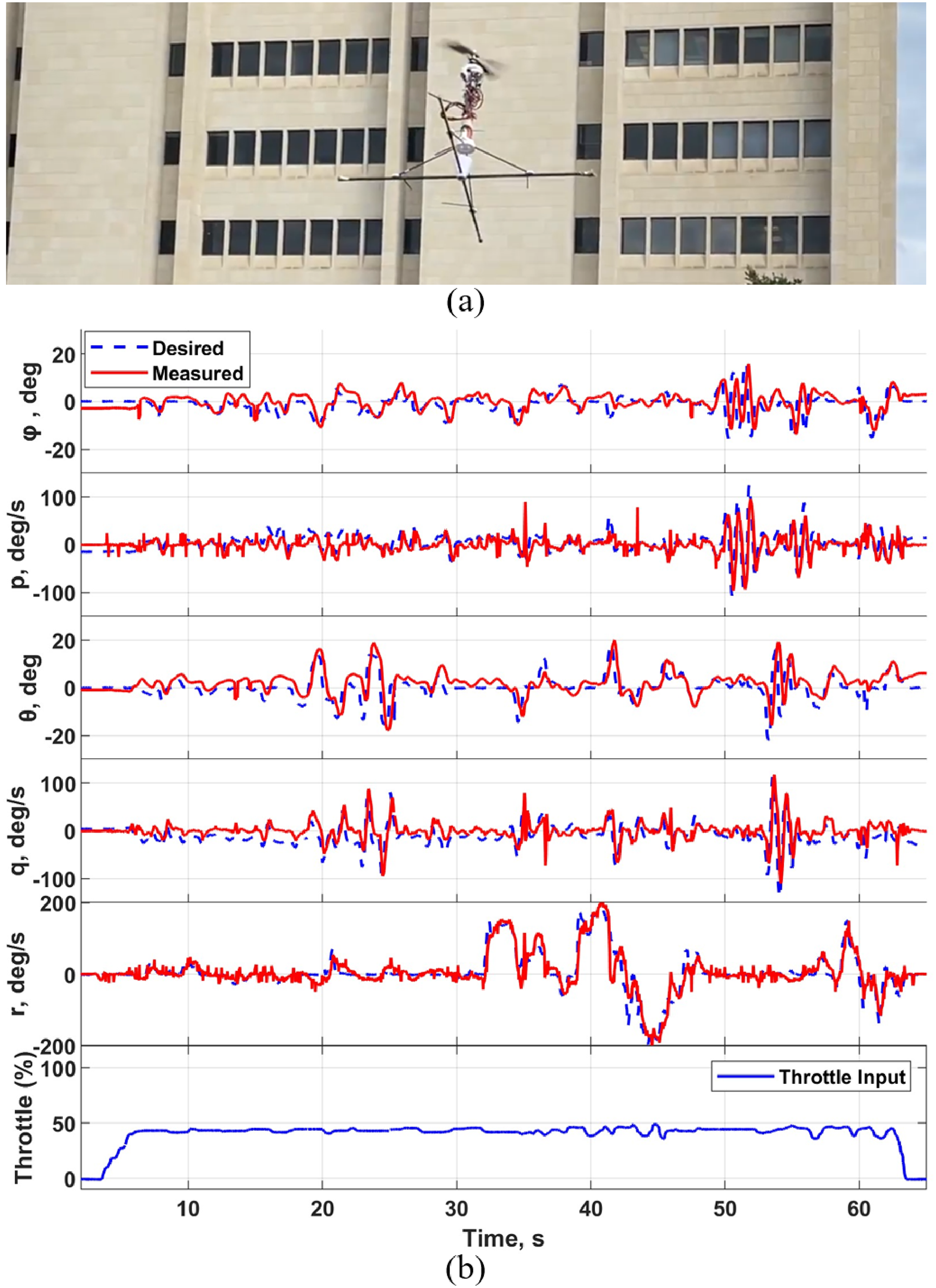
(a) The design prototype using coaxial thrust-vectoring design in a test flight. (b) Sample flight test data (desired and measured roll-pitch-yaw Euler angles, angular rates, and throttle input) from the same flight.
Vehicle design
Followed by the successful demonstration of coaxial-propeller thrust-vectoring design in vertical flight, a VTOL tail-sitter platform installed with the identical propeller system was developed to demonstrate its hovering, cruising, and transition flight capabilities. This section covers the different aspects of the hardware design of the platform. Starting with the requirements, the design of the platform can be categorized into two major parts: (1) a counter-rotating coaxial thrust vectoring propeller system that enables controllable vertical flight, and (2) a foldable traditional fixed-wing aircraft design that enables efficient horizontal flight. The avionics and control systems used for both vertical and horizontal flights are also discussed in this section. The vehicle layout and the weight breakdown are shown in Figure 7 and Table 2, respectively.

Tube-launched VTOL UAV platform layout: (a) Side view; (b) Front view with wings folded; (c) Front view with wings deployed; (d) Top view.
Weight breakdown of the VTOL tail-sitter platform.

Design requirements
The overarching objective of the current design is to demonstrate the vehicle’s VTOL, cruising, and transition flight capabilities while conforming to a compact outer diameter that can fit into a small launch tube with minimal modifications. Along with the controllability considerations highlighted in the previous section, the design is subject to a 6-inch outer diameter constraint to potentially fit inside a 6-inch common launch tube. This spatial constraint drives the majority of the design choices, including a compact propeller system design, a cylindrical fuselage, a foldable wing, and a limited-size tail fin. To facilitate the design process, the 6-inch requirement is currently relaxed for the rotor blades and landing gear considering the fact that these systems could be made foldable in future design iterations. This reduction in complexity has provided ease for the current design iterations, especially in terms of mechanical design, maintenance, and flight testing.
Coaxial propeller and thrust-vectoring mechanism
At the core of the current design is the coaxial propeller thrust-vectoring mechanism, which allows for pitch and roll control in vertical flight as well as provides the required pitching moment for transition from vertical to horizontal flight. This is mechanically accomplished by a counter-rotating propeller and motor system installed on a two-axis gimbal (Figure 8). Note that a body-fixed frame (shown in black) is defined for a better illustration of the gimbal motion.

Coaxial thrust-vectoring mechanism design.
An off-the-shelf counter-rotating propeller and motor system is selected based on the thumb rule that the thrust should be at least 1.5 times the expected weight of the vehicle. Initial tests indicate that the selected
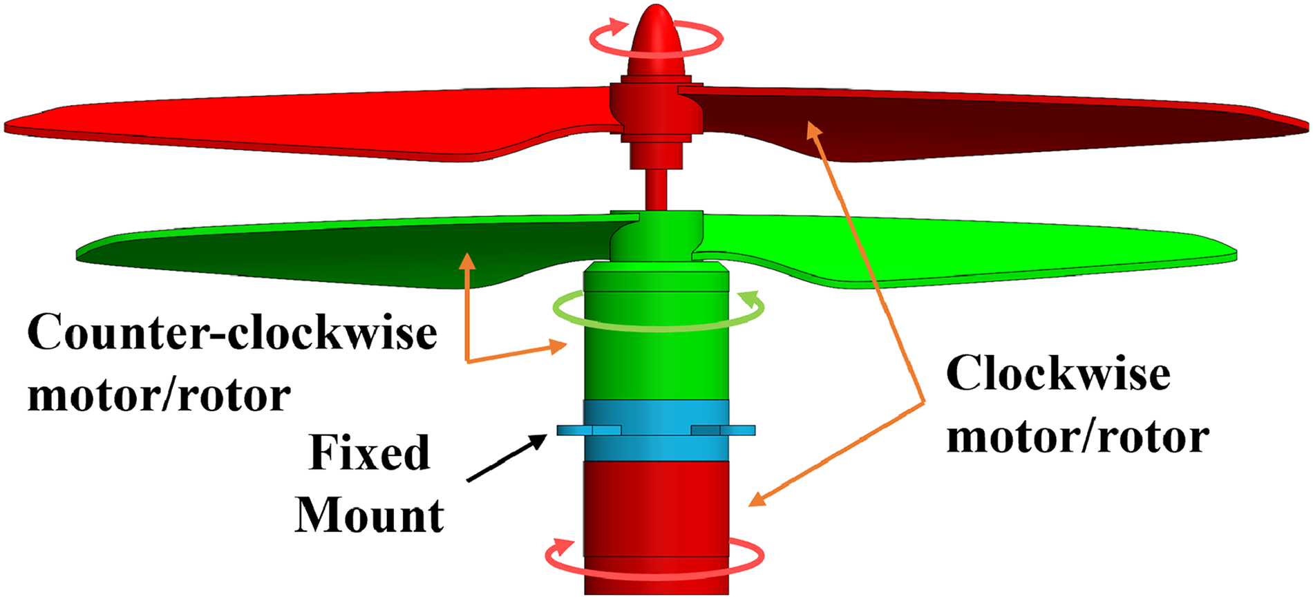
Counter-rotating propeller-motor design.
A similar compact gimbal design in Ref.
4
was adapted to the current design but resized to fit the larger coaxial motor. The two-axis gimbal system consists of two concentric aluminum rings joined by shoulder screws that allow one ring to rotate orthogonally with respect to the other. A close-up of the gimbal rings is shown in Figure 10. The inner gimbal ring has two holes on either side to form the roll axis, and the screws are secured to the tapped holes inside of the outer gimbal. Similar to the inner ring, the outer gimbal ring has a set of holes at a 90-degree phase offset from the x-axis to form the y-axis. The rotation of the propeller-motor assembly about the x- and y-axes is actuated by two separate MKS DS6100 servos through control rods with rod-end bearings on both ends. Driven by the outer ball connector, the outer gimbal will rotate about the y-axis. Since the inner gimbal is mounted 90 degrees from the axis of rotation, the inner gimbal and motor assembly only rotate about the y-axis as the outer gimbal ball connector moves, but the motion does not produce an off-axis control moment. This is because the ball connector for the inner gimbal is along the y-axis while in the neutral position. The combination of the double gimbal with the servo mechanism allows the inner gimbal, and so does the thrust vector, to be tiled with respect to the fuselage. The state of the gimbal tilted by

Two-axis gimbal design.
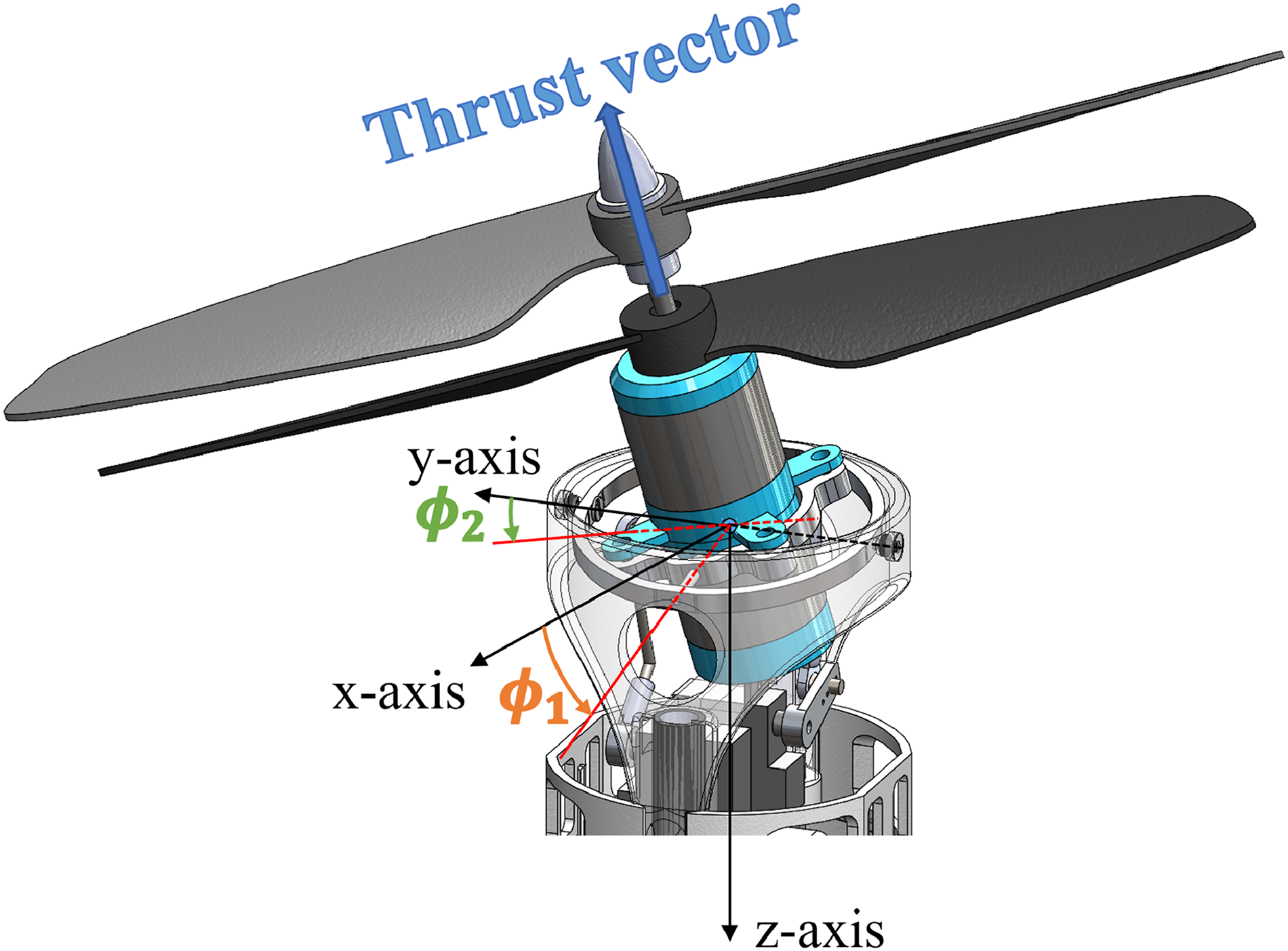
Gimbal tilted about x and y axis.
Horizontal flight design
For horizontal flight, a conventional fixed-wing aircraft design has been implemented, and the layout is shown in Figure 12. One of the key challenges during the design of a tail-sitter aircraft is choosing the vehicle centre of gravity (CG) location relative to the fuselage which is critical for both vertical and horizontal flight stability. For vertical flight, a lower CG (along the vehicle z-axis) leads to better controllability and stability. Conversely, a close-to-nose CG (high CG in vertical flight orientation) location is desirable to ensure a positive static margin (SM) for stable horizontal flight. To maintain compactness and to fold wings onto the fuselage, it is preferred to mount the wings near the nose to prevent an unreasonably long fuselage. Since the location of the neutral point (NP) is highly dependent on the wing location, a close-to-nose mounting location leads to a close-to-nose NP. To be statically stable in horizontal flight, CG is required to be ahead (closer to the nose) of NP, which contradicts the preferred CG location for vertical flight. To overcome this, a design sequence has been developed to ensure the compactness of the design and the longitudinal stability for horizontal flight. First, the battery is placed right behind the thrust-vectoring mechanism to move the CG as close to the nose as possible. Then, the wing is placed at a location such that the CG is at about a quarter-chord distance from the wing’s leading edge. The empennage is then designed accordingly. Note that the final CG of the whole aircraft is slightly moved backward to around half-chord distance from the wing’s leading edge as detailed design finalized.

Fixed-wing design layout.
In order to minimize the transition speed and the design cruise speed, a low-Reynolds-number high-lift airfoil, S1223, was selected. To simplify the design and facilitate the manufacturing process, a rectangular wing was 3D-printed with triangular holes for weight reduction. When both wings are fully deployed, the wingspan of the aircraft is 0.765 m. Note that the lightening holes in the wing were covered with mylar to ensure smooth outer surfaces. All the major parameters for the fixed wing are shown in Table 3.
Fixed-wing parameters for the platform in horizontal flight.

The current empennage is designed to be axially symmetric, which offers several advantages. One benefit is that it can be utilized as a tail fin, effectively moving the aerodynamic centre (AC) of the vehicle (when wings folded) far behind the CG enhancing passive stability during the projectile phase. Additionally, the control surfaces on the empennage offer the potential to control the trajectory during the projectile phase. The current span of the horizontal stabilizer is 0.14 m, which satisfies the launch tube’s 0.15-meter inner diameter constraint. Computational fluid dynamics (CFD) simulations were utilized to determine the longitudinal stability and elevator effectiveness. By running static CFD simulations using STAR-CCM+ at different vehicle angles of attack (

Pitching moment coefficient

Mid-plane velocity field from CFD simulation at cruise with zero-degree angle of attack.
A bird-wing-inspired wing folding mechanism is designed to allow for compactly stowing the wings during launch and vertical flight phases. When a bird folds its wings, the wings retract on both sides, and rotate down and back so that the bottom surfaces face inward and the upper surfaces face outwards when fully folded. Similarly, the vehicle’s mechanism folds the bottom side of the wing onto two sides of the fuselage by a single rotation about a carefully chosen axis. The analogy is also illustrated in Figure 15. By folding the wings separately on both sides of the fuselage, the folding mechanism avoids wing-fuselage interference and maximizes the space inside the fuselage. Additionally, folding the wings spanwise along the fuselage with the wings’ upper surface facing outward maximizes the possible wingspan that can be stored in a cylindrical space constraint while maintaining compactness. More importantly, a rotation axis (defined in Figure 16) is deliberately selected so that only a single rotation is required to fold or unfold the wing. The folding process is also illustrated in Figure 17.

Bird-wing-inspired wing folding mechanism analogy.
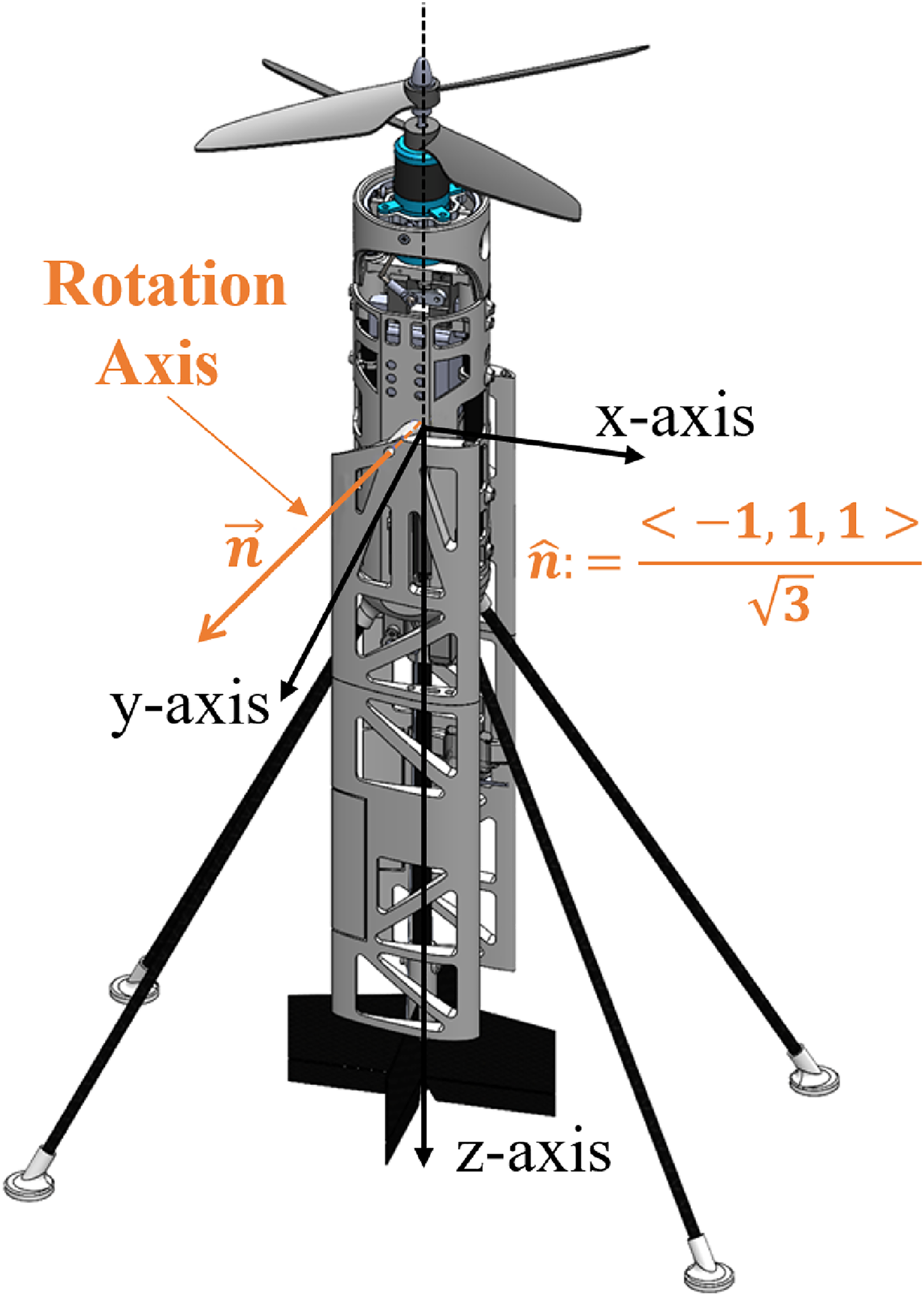
Wing rotation axis direction vector

Isometric view (normal to wing rotation axis) illustrating the wing folding process using figures (a) through (f).
The wing folding mechanism is driven by a linear actuator mounted inside the fuselage, as shown in Figure 18 (a). As the pushrod moves up and down, the wing will rotate around the rotation axis and can be folded or unfolded. This is accomplished by a threaded rod that connects the wing hinge and the pushrod via two ball joints. The three-dimensional degree of freedom from the ball joint converts the linear motion from the linear actuator to the rotation of the wing. Note that an 8mm carbon fibre tube is inserted into the cylindrical rotation shaft of the wing to improve the structural strength as shown in Figure 18 (b). When the wing is fully unfolded, the root section of the wing contacts the flat surface of the fuselage (shown in Figure 18 (c)), which helps to transfer the load from the wing. Moreover, the lift generated by the wing in horizontal flight tends to generate a moment about the rotation axis to unfold the wing, which assists in keeping the wing unfolded in vertical flight. Therefore, in horizontal flight, it is the static support structures, specifically the flat surface on the fuselage and the rotation shaft, that take the majority of the load from the wing and not the linear actuator.

Wing folding mechanism: (a) layout (b) wing folded (c) wing unfolded.
Fuselage
In the current design, a cylindrical shape 3D-printed fuselage is designed to integrate all subsystems. The fuselage is comprised of four distinct parts, as shown in Figure 19. The coaxial propeller system and thrust vectoring mechanism are mounted to parts one and two, the third part accommodates the battery and wing-folding mechanism, and the fourth part houses the autopilot and telemetry module. Two 10 mm carbon fibre tubes run symmetrically through the fuselage, and each part is connected to these tubes with set screws. Plenty of lightening holes have been created on the fuselage, which saves weight and allows for better accessibility to the inner servos and mechanisms. Note that the empennage is connected to the fuselage through another 10 mm carbon tube.

Fuselage structure layout.
Avionics
The vehicle is controlled using a custom-designed lightweight (1.7 grams), size-compact (comparable to a quarter dollar as shown in Figure 20) ELKA-R autopilot. The autopilot is powered by a 5-volt regulator connected to the flight battery. 12 An STM32F405 microprocessor carries out the onboard calculations. The onboard inertial measurement unit (IMU), MPU9250, is equipped with a tri-axial accelerometer, gyroscope, and magnetometer. ELKA-R supports up to 12 Pulse Width Modulation (PWM) actuators. The three Universal Asynchronous Receiver/Transmitter (UART) channels allow for the capability to interface with other devices, such as the telemetry module and the PPM receiver. For real-time stabilization and control, the autopilot senses the vehicle attitude using the IMU, receives command inputs, calculates corresponding corrective outputs, and sends PWM signals to all actuators (e.g., servos, motors, speed controllers, linear actuators, etc.) through PWM channels. A detailed description of the control system is included in the next section.

Custom-designed ELKA-R autopilot.
The autopilot is connected to an XBee 3 Pro Zigbee 3.0 module through one of the UART channels. Operating at 2.4 GHz frequency, this telemetry module allows bi-directional data transmission between ELKA-R and a ground station that is connected to a second XBee. Through this bi-directional communication, the ground station can screen and log data such as attitude and gyroscope measurements from ELKA-R, while the ground station can remotely update the controller parameters in ELKA-R.
The pilot’s inputs are routed from a transmitter to a receiver, which is directly connected to the autopilot. The transmitter used is a Taranis x9d radio control (RC) transmitter that can simultaneously relay up to nine different control inputs from the pilot. These inputs are encoded and sent to a FrSky R-XSR PPM receiver capable of reading eight different input signals to be sent to the autopilot.
Vehicle avionic systems and flight controls
This section discusses how the vehicle’s avionics systems allow for flight control, stability, and flight data collection. The primary avionics components include the autopilot for attitude stabilization and control, a receiver for relaying pilot commands, and a ground station transmission module for telemetry and updating controller parameters. Due to the nature of the tail-sitter design, the pitch attitude for the aircraft in vertical flight has an offset of 90 degrees from the pitch attitude in horizontal flight, as shown in Figure 21. To simplify the explanation for both flight orientations, a body-fixed frame is defined (the black axis system in both (a) and (b)), and the red axis system in (c) is the defined orientation of the inertial frame. This orientation change causes the body frame roll and yaw rotations with respect to the inertial frame to be swapped between the vertical and horizontal configurations. A control strategy has been developed to handle both vertical and horizontal flights. Two different control modes have been implemented in the aircraft: vertical flight (VF) mode and horizontal flight (HF) mode. The physical control mechanism and the control scheme for both modes are also discussed in this section.
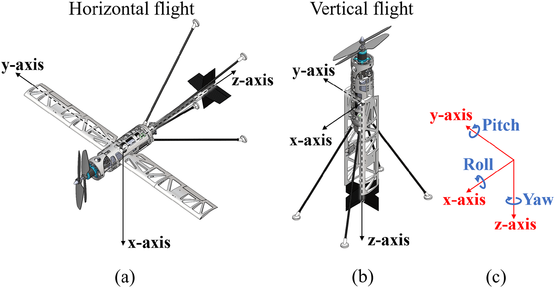
Orientation of the flying vehicle with respect to inertial frame in (a) horizontal flight, (b) vertical flight, and (c) rotations in inertial frame.
Control mechanism
The vehicle’s states can be fully controlled by the PWM signals transmitted by the autopilot to the servos and motors. As previously stated, the thrust vectoring mechanism is actuated by two independent servos that possess sufficient range to tilt the gimbal by

Control moments: (a) moment about body x-axis created by thrust-vectoring mechanism,
Therefore, control moments can always be generated with respect to the body frame regardless of the aircraft’s orientation. Currently, a differential rpm and a thrust-vectoring mechanism are implemented for both flight modes to ensure enough control authority, especially in the pitching direction. As a marginally stable aircraft in the longitudinal direction during horizontal flight, control authority in the pitching direction is essential for controllable horizontal flight. However, two distinct sets of control mappings are implemented for vertical flight mode and horizontal flight mode to provide more intuitive control logic for the pilot. Specifically, the control input is always referenced to the inertial frame. The control mapping for all three directions in each flight mode is provided in Table 4. It should be noted that the current control law implementation allows for rapid enabling/disabling of control surfaces. The effectiveness of the control surfaces will be evaluated once controllable horizontal flight with differential propeller rpm and thrust-vectoring mechanism has been achieved.
Actuator mapping.

For edgewise translation in vertical flight, the gimbal is first tilted in a desired direction until the body rotates, and then the vehicle reacts by translating in that direction. The altitude and heading angle of the vehicle in vertical flight are controlled by varying the rpm of the two motors. The response is regulated according to the rate-based feedback. The imbalance in the propeller torque is used to yaw the vehicle during vertical flight. In horizontal flight, the aircraft is always translating in the opposite direction of its body z-axis. While the x-axis gimbal still controls the pitching of the aircraft, tilting the y-axis gimbal in horizontal flight controls the azimuth (heading) of the platform.
Ground station and receiver
The ground station comprises a Labview VI-equipped computer and an XBee module that allows bidirectional communication with another XBee module directly connected to the autopilot. The Labview programme provides the operator with the capability to wirelessly modify the feedback gains, adjust the trim points of the vehicle’s actuators, and log telemetry data from the autopilot. The telemetry data includes the angular rates, accelerations, attitude angles, and the control signals sent to the servos and motors.
To enable communication between the pilot and the autopilot, a transmitter and receiver are employed. The transmitter takes the pilot pitch, roll, yaw, and throttle commands and sends them to the autopilot via the receiver. Three additional channels were used to arm and disarm all actuators, to fold and unfold wings, and to switch between flight modes, respectively. After being processed by the attitude feedback controller programmed into the autopilot, the commands are transformed into actuator outputs, which are essentially PWM signals. The control scheme will be discussed in the following subsection.
Attitude stabilization and control strategy overview
In both vertical and horizontal flight modes, an identical feedback control strategy is implemented. The controller generates a corrective signal from the feedback to the corresponding actuators (two motors and gimbal servos) based on the control mapping shown in Table 4 to control the roll, pitch, and yaw of the vehicle and create control moments to restore the desired attitude.
To obtain the attitude of the platform, Madgwick’s quaternion IMU fusion algorithm is implemented to filter and fuse the real data from the onboard gyroscope and accelerometer.
13
When converting attitude data from quaternion to roll, pitch, and yaw attitude angles, a 3-1-2 Euler rotation sequence is used to avoid singularity issues that can occur when the aircraft transitions between vertical and horizontal flight modes. Note that the 3-1-2 Euler sequence allows for
The attitude stabilization of the vehicle is accomplished by using a cascaded feedback structure composed of a faster inner loop and a slower outer loop that tracks a desired setpoint (pilot command). According to Schmidt, the cascade controller structure can create a more robust controller design. 14 The control structure is presented in Figure 23.

Feedback controller schematics.
Attitude stabilization and control structure
Starting from the outer loop for pitch and roll control, the pilot commands a desired pitch and roll attitude using an RC transmitter. The pitch and roll control sticks on the transmitter are mapped to produce the desired outputs between
Yaw control is handled using a similar methodology as pitch/roll control, however, with the absence of the outer loop. Since heading hold has not been implemented on the vehicle, the pilot commands a desired yaw rate instead. The yaw stick on the transmitter is mapped between
Flight testing
This section discusses the flight testing of the platform to verify the functionality and controllability of the current design. The flight testing campaign included both vertical and transition flight tests. The vertical flight testing demonstrated the ability of the vehicle to perform stable hovering and edgewise translational flights in both indoor and outdoor conditions. A set of transition flights were then conducted by directly extending the pitch-control range from the vertical flight mode.
Indoor vertical flight testing
The indoor free flight testing was performed in an

Flight test data: Indoor roll command tracking.

Flight test data: Indoor pitch command tracking.

Flight test data: Indoor yaw rate command tracking.
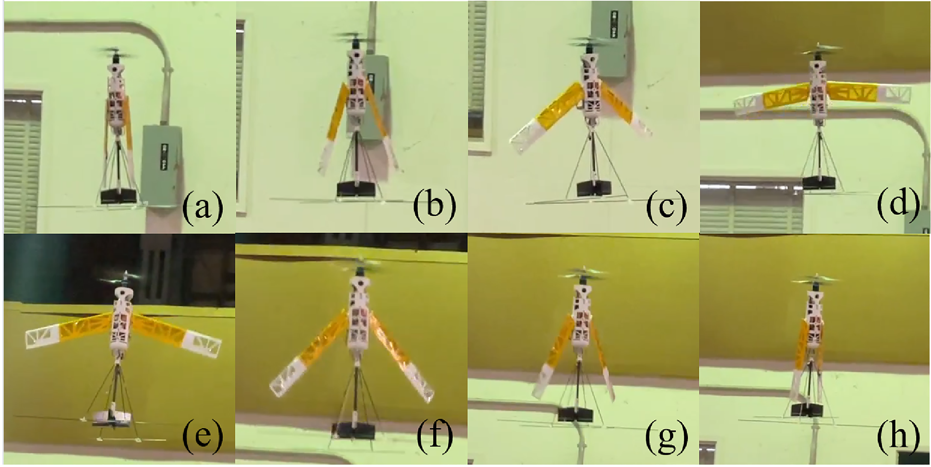
Sequential photographs of (a) through (d) in-flight wing-unfolding process, and (e) through (h) in-flight wing-folding process.
Outdoor vertical to horizontal transition flight testing
For transition flight testing, an extended vertical flight mode with a maximum desired nose-down pitch angle of up to 60 degrees from vertical was implemented on the platform. Since the control surfaces are disabled, the flight testing was able to demonstrate the capability of transition with only the inputs from the thrust-vectoring mechanism. This extended vertical flight mode approach allows for consistent pilot control without switching modes during flight. When testing, the aircraft takes off vertically and then performs a transition as the pilot commands a desired nose-down pitch angle as high as 60 degrees from the vertical while maintaining the roll and yaw orientation. During the flight testing (as demonstrated in the video 18 ), three trials were attempted to demonstrate the capability of vertical-to-horizontal transition flight using the thrust vectoring mechanism. As shown in the flight test data (Figure 28), the aircraft was able to closely track the commanded pitch angle. A maximum of 60-degree nose-down pitching angle or 30-degree fuselage angle of attack (AoA) was achieved, as shown in Figure 29. From the video, it could be seen that the aircraft was able to transition to horizontal flight for a short duration and then return back to hover. These flight tests demonstrated the capability of the platform to transition from hover to horizontal flight and back using the pitch-control authority from the current coaxial propeller thrust-vectoring mechanism. This also shows the potential for controlled horizontal flight with fixed wings by using merely thrust-vectoring-based control and no active control surfaces.

Outdoor vertical-to-horizontal transition flight test roll and pitch data. Note that the euler angles here are referenced from the vertical flight (nose up is corresponding to zero pitch).
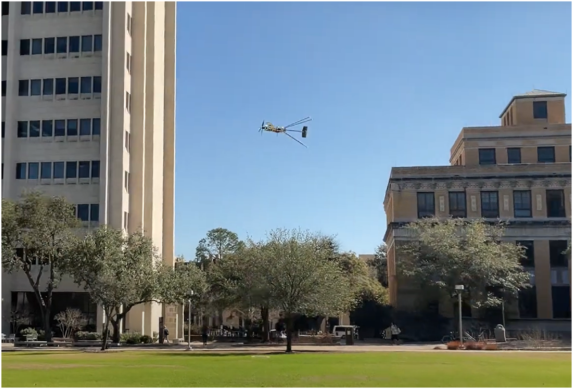
Outdoor vertical-to-horizontal transition flight test.
Summary and conclusions
The overarching goal of the present work is to demonstrate the feasibility of a compact tube-launch capable tail-sitter design with actively foldable wings. The design of this aircraft is divided into two parts: one focusing on vertical flight and the other on horizontal flight. Starting from iterating through a series of control-by-fin designs for vertical flight, a coaxial thrust-vectoring propeller system allowing for sufficient three-axis attitude control as well as compactness for the tube-launched application was finally selected. Then, a conventional fixed-wing aircraft design was incorporated into the coaxial thrust-vectoring propeller for horizontal flight. An innovative bird-wing-inspired folding mechanism was designed to fold the wings during the launch process and vertical flight. A control strategy allowing for control in both vertical and horizontal flight using a cascade PID controller has been implemented on a lightweight custom-designed autopilot. Firstly, the vertical flight and edgewise translational flight with significant control authority for gust rejection were successfully demonstrated. Secondly, a vertical-to-horizontal transition flight was accomplished by extending the desired setpoint pitch angle of zero degrees in hovering flight to a large angle from the vertical to demonstrate the aircraft has enough pitch control authority for transition flight. The key conclusions of this work are enumerated below:
The integration of a coaxial thrust-vectoring propulsion system with a fixed-wing design has been demonstrated, enabling vertical takeoff, landing, and cruise flight capabilities in a tube-launchable UAV. This combination of capabilities represents a significant improvement over the explored active fin control approaches, which exhibited limited performance and control authority. The successful flight tests provide validation of the propulsion system’s effectiveness and the overall design approach. A novel, bird-wing inspired single-axis rotation folding mechanism has been developed and implemented to address the challenge of combining compact stowage for tube-launching with a large wingspan for efficient cruise flight. The in-flight demonstrations of wing folding and unfolding provide initial validation of the mechanism’s functionality and reliability, suggesting its potential for application in morphing UAV platforms. A control strategy using cascade PID feedback loops has been implemented on a custom lightweight autopilot. This control architecture effectively leverages differential motor rpm and the coaxial thrust-vectoring system for attitude control in both vertical and horizontal flights. Flight demonstrations of stable hovering, responsive vertical flight control, and smooth transitions between vertical and horizontal flight modes validate the control strategy’s robustness and adaptability, laying the foundation for the development of autonomous tube-launched VTOL UAVs. The indoor and outdoor vertical flight testing has demonstrated the control authority and performance of the coaxial thrust-vectoring propeller in various operating conditions. The vehicle’s ability to maintain stable hovering and perform translational maneuvers in the presence of wind disturbances indicates the effectiveness of the propulsion and control architecture. These results provide a foundation for the further development and testing of tube-launched VTOL UAVs in real-world scenarios. Flight demonstrations of vertical-to-horizontal transition and back have been conducted, utilizing the pitch control authority provided by the coaxial thrust-vectoring system. These flights demonstrate the vehicle’s capability to transition between vertical and horizontal flight modes without dedicated transition mechanisms. However, the current flight tests did not include a sustained level cruise flight, and further testing is necessary to fully validate the platform’s fixed-wing cruising performance.
Footnotes
Acknowledgements
The authors would like to thank Dr. David Coleman for his help in the early development of the aircraft and flight testing. The authors would also like to thank Melanie Peavy for her early work on the control-by-fin design and wing-folding mechanism. Note that an earlier version of this paper was presented at the Vertical Flight Society’s 79th Annual Forum & Technology Display.
Declaration of conflicting interests
The author(s) declare that there are no potential conflicts of interest with respect to the research, authorship, and/or publication of this article.
Funding
The author(s) received no financial support for the research, authorship and/or publication of this article: This work is jointly supported by Army/Navy/NASA’s Vertical Lift Research Center of Excellence (VLRCOE) (Award Number W911W6-21-2-0003) led by the University of Maryland with Dr. Robert Scott and Dr. Mahendra Bhagawat as Technical Monitors as well as the Army Research Laboratory (ARL) under Cooperative Agreement Number W911NF-21-2-0188. The views and conclusions contained in this document are those of the authors and should not be interpreted as representing the official policies, either expressed or implied, of the Army Research Laboratory or the U.S. Government. The U.S. Government is authorized to reproduce and distribute reprints for Government purposes, notwithstanding any copyright notation herein.