
Abstract
This paper describes the development and flight testing of a compact, re-configurable, hover-capable rotary-wing micro air vehicle that could be tube launched for increasing mission range. The vehicle design features a coaxial rotor with foldable blades, thrust-vectoring mechanism for pitch/roll control and differential rpm for yaw control. The vehicle was stabilized using a cascaded feedback controller implemented on a 1.7-gram custom-designed autopilot. Wind tunnel tests conducted using a single-degree-of-freedom stand demonstrated gust-tolerance up to 5 m/s, which was verified via flight testing. Finally, the 366-gram vehicle was launched vertically from a pneumatic cannon followed by a stable projectile phase, passive rotor unfolding, and transition to a stable hover from arbitrarily large attitude angles demonstrating the robustness of the controller.
Introduction
Micro Air Vehicles (MAVs) find their use in a variety of applications such as intelligence, surveillance, reconnaissance (ISR), as well as search and rescue missions. MAVs provide robust platforms for real-time video or other sensor feeds to the ground operator. The size and maneuverability of rotary-wing MAVs make them especially promising solution for ISR in crowded urban environments. Despite these advantages, the altitude, range, and endurance of these predominantly electric platforms are restricted by the low energy density of current battery technology.1,2 For example, the energy density of commercial lithium-ion cells can reach 200 Wh/kg in ideal settings; however, this energy density can decrease to 150 Wh/kg at the pack level in real conditions.3–5 Limited battery capacity places more stringent constraints on rotary-wing systems compared to fixed-wing aircraft due to the higher power requirement for hovering. Often, rotary-wing MAVs have a hover endurance of less than 20 minutes,1,2,6 making it imperative to consider unconventional approaches to improve the effectiveness of hover-capable platforms for ISR missions.
Although directly improving the endurance of MAVs poses a significant challenge, the overall range could be increased by launching the vehicle as a projectile towards the desired target location. Instead of draining a significant portion of the onboard battery energy to reach the intended altitude and range, the projectile phase of flight would allow for saving the stored energy until the vehicle reaches its designated operating location. The projectile phase also facilitates the rapid deployment of the vehicle since the flight time between the launch and target location is reduced because the deployment speed is limited by the launch speed rather than the maximum vehicle forward flight velocity. From there, the deployment of rotors allows the vehicle to transition to hover mode and perform its mission. This missions profile is presented in Figure 1.

Gun-launched MAV concept: Flight phases.
There are a few existing military platforms that take advantage of a projectile flight phase for rapid deployment and ease of launch without runways; however, most of these are fixed-wing platforms such as the Raytheon’s Coyote 7 and AeroVironment’s Switchblade 8 . Although the fixed-wing platforms tend to have higher endurance compared to the rotary-wing ones, fixed-wing vehicles lack the ability to focus on a single target for an extended duration or navigate in confined spaces. Additionally, almost all the existing platforms utilize specialized launching systems, which can be cumbersome for ground personnel to transport. This equipment must be added to the 87–127 lbs of gear carried by the typical warfighter. 9 The ability to leverage existing equipment like a 40 mm grenade launcher, would significantly increase the convenience and practical applicability of air-launched systems.
In recent years, the development of hover capable, air-launched platforms have begun to emerge such as the Streamlined Quick Unfolding Investigation Drone (SQUID)10,11 developed by Caltech and the Gun-launched MAV (GLMAV)12,13 developed by the French-German Research Institute at Saint Louis. The SQUID is a ballistically launched quad-copter that can be fired from a moving platform. On the other hand, the GLMAV concept is a significantly larger coaxial rotary-wing design. While both these configurations could be scaled down to fit within a grenade launcher, a comparative study conducted in Ref. 14 determined that a coaxial rotor system was a better candidate for the proposed mission profile. This assessment was based on factors such as efficiency, folding compactness, and ease of packing.
The overarching goal of this research effort is to develop a coaxial rotor based MAV that could be launched from a grenade launcher. However, developing this platform presents some key technical barriers which stem from scaling the vehicle down to fit within the barrel of a grenade launcher which has an inner diameter of 40 mm, in-flight reconfiguration (passive rotor deployment from a folded state), and the complex dynamics experienced during the transition from projectile to hovering mode. Some specific challenges include (1) designing and building a compact rotorcraft with outer diameter less than 40 mm, (2) foldable coaxial rotor blades with passive unfolding strategies which avoid rotor collision, (3) simplified and compact swashplateless pitch, roll and yaw control strategies, (4) ultralight-weight autopilot with small footprint, (5) ability to handle the high accelerations of an explosive take-off, (6) passive and active control strategies ensuring stable attitude dynamics in flight, especially during the transition from the projectile mode to the hovering helicopter mode, (7) optimizing the rotor-motor-ESC (electronic speed controller) combination to achieve a hover endurance of at least 30 minutes, and (8) understanding and improving the controllability and disturbance rejection (gust tolerance) of the vehicle in hover for improved robustness in adverse conditions.
The platform’s compactness and in-flight reconfiguration and transition requirements necessitate a multifaceted approach to the vehicle design. To facilitate development, the size constraint was slightly relaxed and an intermediate prototype was developed. The intermediate prototype had an outer diameter of 52 mm instead of the required 40 mm diameter. Future iterations will miniaturize this intermediate prototype by optimizing and scaling the components for the final 40 mm design. The objective of the present study was to enable the vehicle to achieve a stable projectile phase, deploy the rotors, and then successful transition from the projectile phase to a stable hover, following a vertical launch. This required many innovations in the vehicle design, rotor deployment mechanism, controls system, and systematic flight testing, which are discussed in this paper.
Vehicle hardware design
This section provides an overview of the current vehicle hardware design, and the design choices that have influenced the current 52 mm outer-diameter platform. Note that the present design is for the vertical launch configuration where the vehicle is launched with rotor at the top. The sub-sections are composed of the design requirements and the major subsystems of the vehicle including the thrust-vectoring mechanism, coaxial-motor, folding rotor, avionics, fuselage. The vehicle layout is show in Figure 2 and the the weight breakdown is provided in Table 1.

Gun-launched MAV layout.
Weight breakdown of the flying vehicle.

Design requirements
The current design was driven by a set of requirements, especially, the spatial constraints imposed by the 40 mm (1.6 in) grenade launcher, which drove the majority of the design decisions for the overall configuration. The final goal is to launch vehicle to a range of 100 meters and achieve an endurance of 30 minutes or more. The vehicle should be capable of carrying a 10 gram payload consisting of a camera and video transmitters for ISR missions. Additional sensors could be added in the future as electronics packages are continually miniaturized. Both multi-rotor and single-rotor configurations were considered; however, these configurations were not selected due to the complexity required to fold the arms and restrictions on the sizes of components such as the motors, rotor, and servos.
Due to the cylindrical outer-body-shape constraint, a coaxial helicopter configuration became the natural choice because a cylindrical shell could be used as the body and the rotor blades could be easily folded against the body. The coaxial configuration also benefits from a more compact yaw control mechanism by balancing the torque produced by the counter rotating rotors, whereas a traditional single rotor helicopter requires a tail rotor that extends from the body for yaw control. Another advantage is the lower disk loading of the coaxial configuration that can offer longer endurance and lower noise signature compared to a multi-rotor such as a quad-rotor of the same footprint. 3 To further reduce the complexity and for ease of blade folding, a gimbaled-hub based thrust-vectoring mechanism is used in place of mechanically complex swashplates to control pitch and roll in conjunction with fixed-pitch rotors. This reduced complexity should improve the overall reliability of the system when subjected to launch accelerations.
Thrust-Vectoring mechanism
Pitch and roll control is implemented by tilting the thrust vector which creates pitch and roll moments about the center of gravity (CG) of the vehicle, located below the rotor plane. This is mechanically accomplished by mounting the motor-rotor assembly at the center of a two axis gimbal as illustrated in Figure 3. The gimbal consists of two concentric aluminum rings joined by shoulder screws that allow one ring to rotate orthogonally with respect to the other. A close up of the gimbal rings are shown in Figure 4. The rotation of the motor-rotor assembly about the pitch and roll axes is actuated by two separate servos through control rods with rod-end bearings on both ends. The combination of the double gimbal with the servo mechanism allows the thrust vector, which normally passes through the CG, to be pointed forward/aft (pitch control) or left/right (roll control), similar to a teetering rotor. This tilt of thrust vector creates moments about the CG that cause the vehicle to rotate and translate in a desired direction. The differential rpm of the counter-rotating motors achieves yaw control.
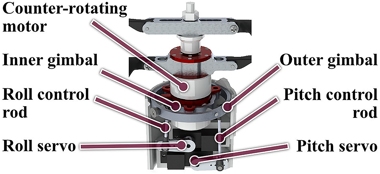
Two axis gimbal for thrust vectoring.

Close-up of the two axis gimbal.
Counter-Rotating motors
An integrated motor system reduces the complexity of the thrust-vectoring mechanism. The motor unit consists of two brushless DC motors stacked on a common body. The upper motor attaches directly to one rotor. The lower motor attaches to a second rotor via an extended shaft. Bearings isolate the shaft from the upper motor and its rotor. Figure 5 depicts this arrangement. Mechanically decoupling the two motors in this manner allows the rotors to rotate independently and provides separate interfaces for electronic speed controllers (ESCs). Additionally, the independent control of the motors allows for yaw control through differential rpm of the fixed-pitch rotors.

Counter-rotating motor.
Rotor design
Another key component of the vehicle design is the pair of counter-rotating folding rotors, which were designed to conform to the body of the vehicle when folded. Since the rotor blades needed to fold against the body, a circular cambered-plate airfoil was chosen to reduce the volume taken-up by the slots for the blades. The maximum camber for the circular cambered-plate is located at the 50% chord location. This also allowed the blades to be concentric with the body when folded as shown in Figure 6. Moreover, thin, circular cambered-plate airfoils with moderate camber (5%–9%) have been shown to be more efficient for MAV scale rotors operating at low Reynolds numbers (30,000 – 60,000).15–18 The outer diameter of the rotor in the folded configuration is 51.5 mm (2.03 in), which is equal to vehicle body diameter. The diameter of the rotors, when fully unfolded is 228.6 mm (9 in). The propellers are folded into the body using a flap hinge that is located between the root of the blade and the rotor hub as illustrated in Figure 7. The flap hinge is designed to provide enough friction to prevent the rotors from freely flapping, and a mechanical stopper on the hub limits the flapwise rotation to 90 degrees while unfolding. The chord varies linearly with radial location and the taper ratio and 75% chord are listed in the Table 2. The other parameters such as rotor diameter, blade sectional thickness, pitch angle at 75% span location, camber, constant twist angle, and rotor solidity (ratio of blade area to rotor disk area), are also listed in Table 2. Most of the blade parameters were chosen based on previous MAV-scale rotor design studies.19,17

The rotor airfoil conforming to the cylindrical body.

The rotor blades folding about a hinge to fit into a slot in the body.
Rotor parameters.

Rotor and hub manufacturing
Given the specific design constraints on the rotors, a rapid prototyping technique was chosen for manufacturing. The rotors were 3D printed using a fused deposition modeling on a Prusa Mk3 using polylactic acid (PLA) with a layer height of 0.1 mm (0.004 in). The low layer height was used to create a smooth surface finish, but the rotors still required post-processing. After printing, the rotor blades were carefully sanded to achieve acceptable surface finish levels. The leading and trailing edges of the blades were sharpened to the extent possible because previous studies have shown that sharp leading and trailing edges improve aerodynamic efficiency at low Reynolds numbers.20,21 In order to balance the rotor and reduce unwanted vibrations, each individual blade was weighed and the blades were paired based on the mass. The paired blades were then mounted to the upper and lower rotor hubs and carefully balanced on a rotor balance via adding steel washers. Static and dynamic rotor balancing is critical to achieving clean performance measurements.
Rotor testing
A custom-designed hover test stand was used to quantify the performance of the rotors. The hover stand, shown in Figure 8, consists of a dual axis load cell to measure rotor thrust and torque, an optical rpm sensor, and a power supply. The counter-rotating motor was connected to a set of two electronic speed controllers (ESCs) so that the rotational speeds (rpms) of the motor could be controlled independently. The power supply was set to 12 volts according to the motor manufacturers recommended 3-cell voltage. The initial tests were conducted using a single rotor mounted to the counter-rotating motor.

Hover test stand.
The resulting thrust and torque measurements are shown in Figure 9. The mechanical power from the test is shown in Figure 10. The test also verified that the rotor could withstand the rotating loads. Next, the second rotor was added to the setup to measure the performance of the complete coaxial system. For the coaxial test, the rotors were tested at the same rpm, but the measured torque was approximately balanced as seen in Figure 11 along with the resulting thrust. The coaxial rotor test showed the rotor design exceeded the thrust requirement of 366 grams (3.59 N) for hover. The maximum thrust-to-weight ratio was about 2, which is sufficient excess thrust for control and forward flight. It was noted that the net torque produced by the rotors was near zero. This result indicated that only minor adjustments may be necessary to trim the moment about the yawing axis of the vehicle during flight.
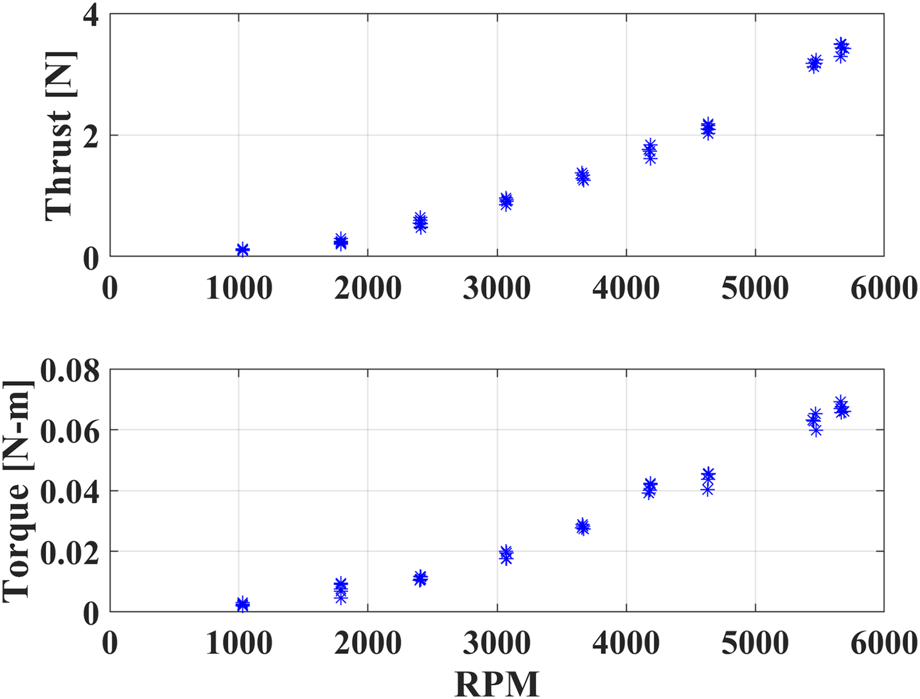
Single rotor: Thrust and torque vs. RPM.

Single rotor: Mechanical power vs. RPM.

Coaxial rotor: Thrust and torque vs RPM.
Avionics
Due to the size constraints, the vehicle required a custom and re-configurable autopilot for carrying out stabilization and control tasks. Hence a custom-designed ELKA-R autopilot was used because of its compact size (one inch square), lightweight (1.7 grams) and the ability to customize the flight control algorithm. 22 The autopilot is powered by a 5V regulator connected to the flight battery. A size comparison of the autopilot is shown in Figure 12. ELKA-R is equipped with a STM32F405 microprocessor for all onboard computations tasks. The integrated MPU9250 is equipped with tri-axial accelerometers, gyroscope and magnetometer. These sensor measurements are used to determine the attitude of the vehicle, and details of the control system are included in the next section. Board supports up to 12 Pulse Width Modulation (PWM) actuators when two of the three Universal Asynchronous Receiver/Transmitter (UART) channels are converted to four PWM channels. The PWM channels are used to send control signals to the motors and actuators at a speed of up to 1000 Hz. The three UART channels can be used to read sensors or send data to other devices such as the telemetry module and the PPM receiver.

Compact 1.7g ELKA-R autopilot used for stability augmentation and control.
The telemetry module is a XBee 3 Pro Zigbee 3.0 that operates at 2.4 GHz and is connected to the autopilot using a breakout board. This module allow ELKA-R to transmit data such as attitude and gyroscope measurements to a second XBee connected a ground station. The module is also used to receive information from the ground station such as the updated controller parameters.
The pilot’s inputs are routed from the transmitter to the receiver, which is directly connected to the autopilot. A Taranis x9d transmitter is used to relay pilot commands, and it is capable of sending up to nine different control inputs at the same time. These inputs are encoded and sent to a FrSky R-XSR PPM receiver capable of reading eight different inputs signals to be sent to the autopilot.
Fuselage design
The fuselage (or body) of the vehicle acts as the anchor point for all of the major components and is designed to fit within the pneumatic cannon. The body also consists of a side panel and a battery cage to access the electronics and battery. The outer diameter of the body is 51.5 mm to fit within a standard 2 inch schedule 40 pipe used for the barrel of the pneumatic cannon. The thrust vectoring mechanism is attached to the main body using shoulder screws and press nuts. Around the outer gimbal are the slots that were made to house the folded rotor blades. Below the gimbal are the mounts for the servos. The autopilot and the telemetry modules are mounted to a breakout board that serves as a mounting plate, which is soft-mounted to the main body using threaded inserts and vibration dampening screws. This assembly is shown in Figure 13. A battery cage is installed at the bottom part of the fuselage, which prevented the lithium polymer battery from shifting during flight. The cage also allowed easy replacement of the battery. All of the internal components are accessible by the access panel that conforms to main body and is attached by four screws. The fuselage was rapid prototyped out of ABS plastic.
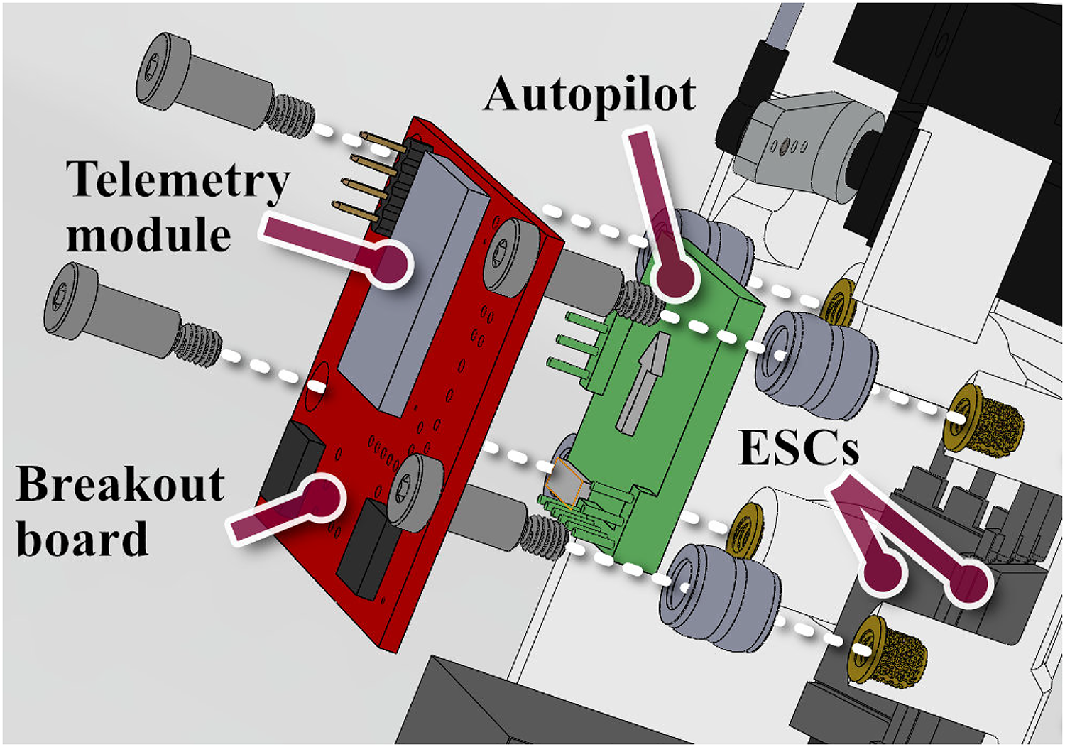
Exploded view of the autopilot and telemetry modules placement on the vehicle.
Vehicle avionic systems and flight controls
This section discusses the interactions between the various components within the vehicle’s avionics system that allows for flight stability and flight data collection. The major components include the autopilot for attitude stabilization, the motor and servos for initiating attitude changes, the ground station for telemetry and updating controller parameters, and the receiver for relaying pilot commands.
Control mechanism
The control PWM signals sent by the autopilot to the servos and motors enable full control of the vehicle’s states. As explained before, the thrust vectoring mechanism is actuated by two independent servos. The servos possess enough range to tilt the gimbal by

Rolling/pitching moment created by the thrust-vectoring mechanism.
The altitude and heading angle of the vehicle is controlled by varying the rpm of the two motors. To increase the altitude of the vehicle, the rpm of both the rotors needs to be simultaneously increased while maintaining the yaw torque balance. Since the upper rotor tends to aerodynamically interfere with the lower rotor, simply increasing the power to both motors would result in an imbalanced torque about the yaw axis as shown in Figure 15. This torque is balanced by increasing power to the lower rotor and decreasing power to the upper rotor. The response is regulated according to the rate based feedback. The imbalance in the rotor torque is also used to yaw the vehicle during flight. If the reaction torque of the upper rotor, Q1, is less than the reaction torque of the lower rotor, Q2, the net torque will create a yaw rate, r, in the same direction as Q2.
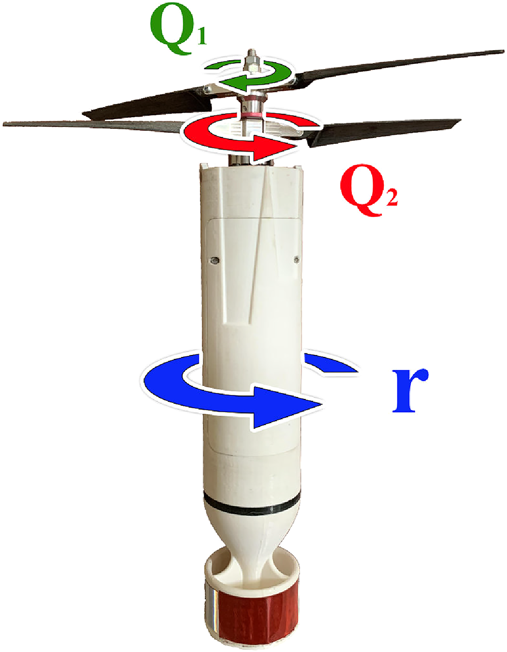
Yawing moment created by differentially varying the rpm of the rotors.
Ground station and receiver
The ground station consists of a computer with a LabVIEW VI and a XBee module to send and receive telemetry from another XBee directly connected to the autopilot. The LabVIEW program allows the operator to wirelessly update the feedback gains, change the trim points of the vehicle’s actuators, and record telemetry data from the autopilot. The telemetry data includes the angular rates, accelerations, attitude angles, and the control signals sent to the servos and motors.
The transmitter and receiver facilitates the interaction between the pilot and the autopilot. The transmitter takes the pilot pitch, roll, yaw and throttle commands and sends them to the autopilot via the receiver. The commands are converted to PWM actuator outputs after being processed by the attitude feedback control programmed into the autopilot. The control scheme will be discussed in the following subsection.
Attitude stabilization overview
The attitude of the platform is obtained from the measured body-axis angular rates (gyroscope) and the tilt of the gravity vector (accelerometer). These measurements are filtered and fused to determine the pitch and roll attitude of the vehicle during flight. The Euler angles can be calculated by integrating the time history of the gyro measurements. However, gyro-based attitude measurements are known to drift over time. 23 The accelerometers are used to offer a stable bias for this drift, but the measurements are often polluted by high frequency noise. 24 Therefore, a complementary filter was implemented to calculate the roll and pitch Euler angles using a high-pass filter on the gyros data (4 Hz cut-off) and a low-pass filter for accelerometer data (6 Hz cut-off). These attitude measurements are fed back to the controller to stabilize the pitch, roll, and yaw of the vehicle.
The feedback control architecture will be discussed in the following subsection. The controller outputs a corrective signal from the feedback controller to the two motors and servos. The pitch and roll of vehicle is controlled by the servos through tilting the two-axis gimbal to create control moments to restore the vehicle to the desired attitude. Yaw of the vehicle is controlled by differentially varying the rpm of the upper and lower rotors.
Attitude stabilization control structure
The attitude stabilization is accomplished using a cascaded feedback structure composed of a faster inner loop and a slower outer loop that tracks a desired setpoint. According to Reference 25 , the cascaded controller structure can create more robust controller design. 25 The differing loop speed is also important because the gyroscope are sampled at a higher speed of 1000 Hz compared to the attitude estimation speed of 200 Hz. The following control structure is presented in Figure 16.

Controller feedback diagram. (a) Pitch and roll attitude feedback. (b) Yaw rate feedback.
Starting from the outer loop for pitch and roll control, the pilot commands a desired pitch and roll attitude using a RC transmitter. The pitch and roll sticks on the transmitter are mapped to produce the desired outputs between
Yaw control is handled using a similar methodology as pitch/roll control, however, without the outer loop. Since heading hold has not been implemented on the vehicle, the pilot commands a desired yaw rate instead. The yaw stick on the transmitter is mapped between
Gust disturbance rejection testing in wind tunnel
This section discusses the process used to verify the ability of the controller to handle the disturbances that may be experienced by the vehicle during recovery from launch or flight in gusty conditions. The procedure involved tuning the pitching response of the vehicle on a single degree-of-freedom (DOF) stand and then subjecting the vehicle to disturbances in a closed-circuit low-speed wind tunnel. The test stand described here is shown in Figure 17. The pitch-axis of stand was designed to pass through the CG of the vehicle to simulate free flight.
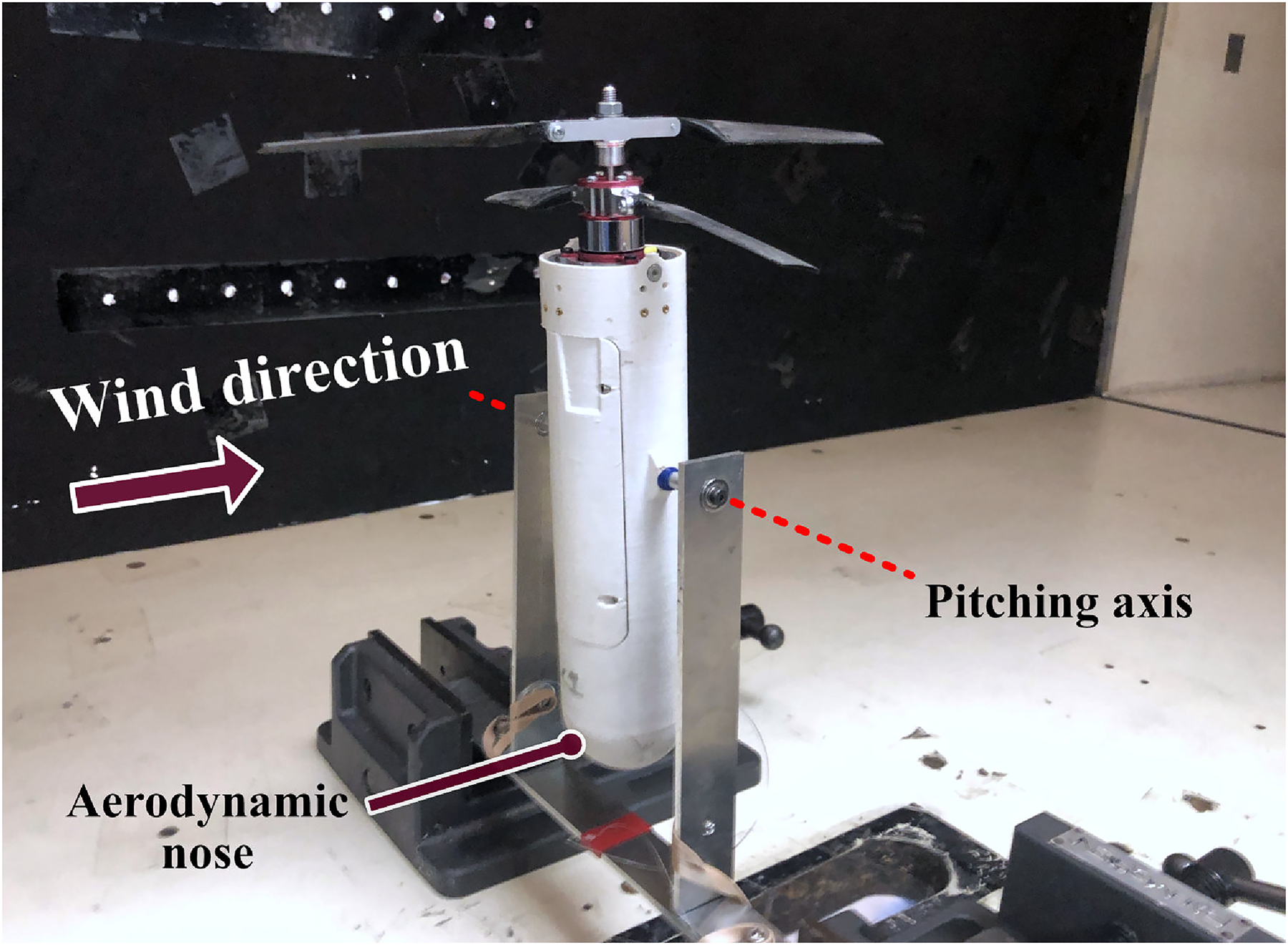
Vehicle mounted on single DOF test stand in wind tunnel.
The objective of this test was to evaluate the ability of the controller to hold a desired pitch forward attitude in the presence of a constant gust. The vehicle was placed in an upright position on the stand in the center of the 3 ft by 4 ft wind tunnel test section (Figure 17) and the airspeed was set to the desired value. The coaxial rotor system on the vehicle were powered and the rotational speeds were set to the hover values. Then a step input was provided to command the vehicle to a 25 degree pitch forward attitude. The command was held for five seconds and then brought back to zero for five more seconds.
These tests were performed at wind speeds between 3 and 6 meters per second (m/s), and the pitch response was recorded using the telemetry module. A video of one of these tests can be viewed in Ref., 26 and the results are shown in Figure 18. For this test, the vehicle was subjected to a 5 m/s wind speed, and the controller was able to track the commanded 25 degree step input with a minimal transitory response that is imperceptible to a human pilot. Similar performance was noted at 3 m/s; however, at 6 m/s, the vehicle took longer to reach the desired attitude. Although, after testing the vehicle in free flight, it was noted that in forward flight and in the presence of moderate winds, the vehicle’s attitude in pitch rarely exceeded 10 degrees. In hindsight, a 10 degree step input could have been a more representative case as opposed to 25 degrees. The results of these tests provided enough confidence in the controller to begin free flight testing.
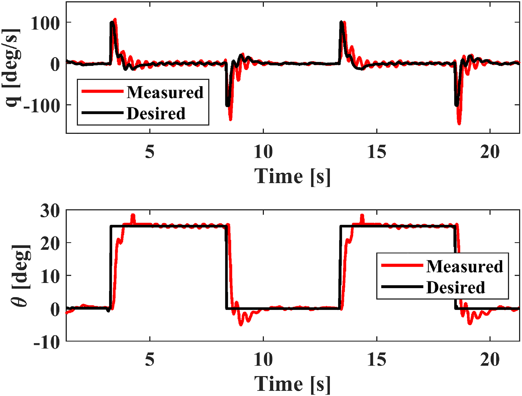
Pitch response to step input when the vehicle was subjected to a 5 m/s wind speed.
Hover tests
In the next stage of testing, the vehicle was removed from the test stand and free flight testing in hover was conducted to ensure the vehicle was capable of stable flight under indoor and outdoor conditions. For indoor flight testing, the vehicle was flown in an
The first set of hover tests were performed to verify that the controller gains that resulted from the stand testing were transferable to free-flight conditions. Since the vehicle is approximately axi-symmetric about the yaw axis, the controller pitch gains determined from stand testing were also applied to the roll gains. The yaw gains were tuned via flight testing. Although the vehicle could be flown with the previously determined gains, fine tuning was necessary to improve the vehicle response and handling qualities in hovering flight. The pitch response shown in Figure 19 indicated that the controller is able to hold zero rates and attitude angles, and this result was similar in the case of roll response as well.

Pitch response during hover.
The indoor tests were followed by extensive outdoor testing in moderate wind conditions (wind speeds up to 5 m/s) and the vehicle demonstrated satisfactory stability and controllability, which corroborated with our wind tunnel test results. The current maximum hover endurance for the vehicle is 10 minutes. Further optimization of the rotors, motors, and structure will have to be performed to reach an endurance of 30 minutes.
Vertical launch tests
This section discuses the final steps taken before the vehicle could be launched in the vertical configuration. A “dummy” with similar shape and inertial properties as the actual vehicle was launched vertically from a pneumatic cannon to check if the fin assembly could stabilize the vehicle after launch. Before the vehicle could be launched, the rotor startup sequence (deployment from the folded state) had to be tested. Finally, a vertical launch of the vehicle was performed.
Vertical dummy launch
The analogue to the flying vehicle or a “dummy” was designed to test the passive stability of the vehicle with the fin assembly during the unpowered projectile phase of flight. The dummy could be launched without risking the more fragile components in the actual flying vehicle. More importantly, the dummy launch serves as a perfect rehearsal for the vehicle launch. The dummy was designed as close as possible to the actual flying vehicle and consisted of all the same components except for the actuators, thrust-vectoring mechanism, and flight battery. Similar shape, overall dimensions, and mass distribution were used to ensure that the dynamics of the dummy during the vertical launch would be close to that of the flying platform.
The dummy was also used to test the response of the autopilot’s sensors after experiencing the high initial launch acceleration to make sure their ratings are not exceeded. Since both accelerometer and the gyro measurements are used to estimate the vehicle attitude for stabilization, it was crucial to the verify that sensors would be reliable after the launch phase.
The test launch of the dummy was performed in an open and relatively flat field that was free of obstacles and people. First, the pneumatic cannon was pressured to 70 psi (482 kPa), and then the cannon was positioned at a near vertical angle. Then the battery was plugged in to power the electronics in the dummy. Once the ground station began receiving from the telemetry module, the dummy was lowered into the cannon with the fin assembly pointing down.The relative locations of the AC and CG was designed to prevent the dummy from tumbling during launch. Finally, the ground station began recording data, and the solenoid controlled valve was triggered to launch the dummy.
Overall, the launch of the dummy appeared to be stable from launch until the apex of the trajectory was reached. After reaching the apex, as expected, the dummy began to tumble at low speeds, and the vertical acceleration, pitch, and roll response are shown in Figure 20. According to the vertical accelerometer readings (blue line), the launch occurred at 14.5 seconds and the dummy impacted the ground at 18.7 s. If it is assumed that the apex is reached at half of the flight time, based on the pitch and roll angle measurements, the dummy remained at an attitude less than

Attitude response of dummy after launch.
Rotor deployment
Since the rotors needed to be folded to be inserted into the cannon for the vertical launch of the vehicle, an unfolding strategy needed to be perfected before the launch. The most obvious method was to spin up the upper rotor followed by the lower rotor. The centrifugal force acting on the blades would allow the them to naturally unfold and deploy.
The rotor startup sequence was programmed into the autopilot and was triggered after the throttle signal passed a preset threshold. When the vehicle is powered, the servos hold the thrust-vectoring mechanism in the trim position while the vehicle is in the barrel of the cannon. In the trim position, the blades are retained within their respective slots in the fuselage. After launch, once throttle is above the threshold, the upper rotor begins to spin-up. Approximately one-eighth of a second later, the lower rotor begins to spin. This short delay is long enough to keep the counter-rotating blades from impacting each other. Once both rotors are spinning, the autopilot controller begins stabilizing the vehicle.
The startup sequence was tested numerous times on the vehicle before flight. As long as the friction in the flapping hinge is not too high, the rotors were shown to reliably spin up without any issues. A video of the rotor startup sequence can be found in Ref. 27 .
Vertical vehicle launch
After all the tests mentioned above were successfully completed, the vehicle was ready for the vertical launch. Similar to the dummy test, the cannon was pressurized to 70 psi (482 kPa), and the cannon was positioned at a near vertical angle. After plugging in the vehicle battery, the rotors were folded, the rotor startup sequence was checked, and the vehicle was lowered into the cannon with the fin assembly pointing down. The vehicle was launched by triggering the solenoid.
When the vehicle was launched, the fin was able to keep the vehicle relatively stable up to the apex of the vertical trajectory. At that point, the pilot provided a throttle command to begin the rotor startup sequence, and the sequence was captured in Figure 21. As expected, the upper rotor began spinning first followed by the lower rotor, and controller began to stabilize the vehicle.

Vehicle recovery sequence after launch.
During one of the launches, the vehicle began tumbling shortly after rotor startup, but after a few seconds, the controller was able to stabilize the vehicle. This particular launch, that can be seen in Ref.,
28
demonstrated that the vehicle could even recover from an arbitrarily large attitude angle. The pitch and roll response of the vehicle is plotted in Figure 22. The plot shows that the launched occurred at the 36.5 s mark denoted by the initial spike in the blue line, and the attitude data prior to the rotor deployment are similar to the ascent phase of the dummy. We consider the successful vertical launch to be a crucial milestone in achieving our final objective of a gun-launched system by demonstrating the ability to:
Launch the vehicle from a small tube at high accelerations. Stabilize the vehicle during the projectile phase using a fin assembly that does not protrude out of the vehicle profile. Passively deploy the rotors in flight using the centrifugal force. Recover the vehicle from the projectile phase and bring it to a stable hover.
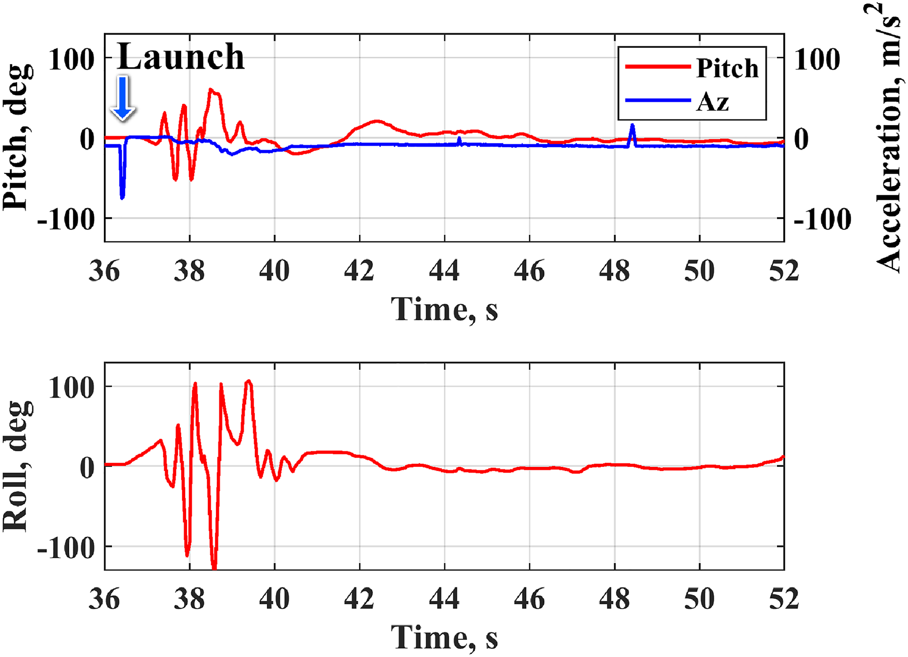
Vehicle attitude response during vertical launch and recovery. Launch occurred at 36.5 s.
Summary and conclusion
The overarching goal of the present work has been to demonstrate the feasibility of a compact and re-configurable rotary-wing MAV that can potentially be launched from a 40 mm grenade launcher. The MAV was designed using coaxial rotors with foldable blades, a thrust-vectoring mechanism (instead of swashplates) for pitch and roll control, and a strict constraint on the outer diameter to fit inside a 52 mm inner diameter tube. The thrust-vectoring based control reduced the complexity of the system thereby improving reliability. Yaw control was accomplished through a specialized counter-rotating motor unit that is composed of two independently controlled motors. The vehicle attitude was stabilized using a cascaded PID feedback controller implemented on a 1.7 gram custom-designed autopilot. Before the controller could be used on the vehicle in free flight, its effectiveness was investigated via a series of disturbance rejection experiments in the wind tunnel with the vehicle mounted on a single DOF test stand. In the next phase, free flight testing was conducted both indoors and outdoors in moderate wind gusts. Finally, a vertical launch experiment of the vehicle was performed. The key conclusions of this work are enumerated below:
A compact and mechanically simple thrust-vectoring mechanism used in place of swashplate for pitch and roll control was demonstrated. Pitch and roll control moments were generated by tilting the rotor plane which created moments about the CG. The thrust-vectoring mechanism possessed sufficient control authority for stable hover and disturbance rejection. Single and coaxial rotor hover stand experiments showed that the 3D printed rotor blades could withstand the centrifugal and aerodynamic loads and produce sufficient thrust for the vehicle. Rotor deployment of a coaxial configuration using only centrifugal force was demonstrated. A staggered rotor startup sequence prevented the upper and lower rotors from impacting each other during unfolding. Wind tunnel, free flight, and vertical launch experiments demonstrated sufficient controller authority using a thrust vectoring mechanism in conjunction with cascaded feedback controller. The vehicle was able to track a desired attitude input in the presence of a 6 m/s forward wind speed. The final vertical launch experiment demonstrated that the vehicle could even recover from arbitrarily large attitude angles after rotor startup. The controller and thrust-vectoring mechanism managed to stabilize the vehicle after it began to tumble shortly after launch.
Footnotes
Acknowledgements
The authors would like to thank Dr. Vikram Hrishikeshavan for his assistance with programming the ELKA-R autopilot. The authors would also like to thank Grant Erickson and Grant McCurdy for their assistance with wind tunnel and vertical dummy launch experiments.
Declaration of conflicting interests
The author(s) declared no potential conflicts of interest with respect to the research, authorship, and/or publication of this article.
Funding
Research was sponsored by the Army Research Laboratory and was accomplished under Cooperative Agreement Number W911NF-21-2-0188. The views and conclusions contained in this document are those of the authors and should not be interpreted as representing the official policies, either expressed or implied, of the Army Research Laboratory or the U.S. Government. The U.S. Government is authorized to reproduce and distribute reprints for Government purposes notwithstanding any copyright notation herein.