
Abstract
A theoretical model is built to reveal the effect of the joint clearance on the kinematic performance of the transmission mechanism of a flapping wing micro aerial vehicle (FWMAV). Massless link approach is used to model the joint clearance and the reciprocal screw is introduced to solve the kinematic model. Finite element method simulations are also performed to validate the model. The kinematic model reveals that the inertia force of the transmission mechanism contributes little to the flapping motion whereas the sign of the resultant moment of aerodynamic drag and wing inertia force plays decisive role. Besides, the joint clearance can either increase or decrease the flapping angle of the wing during a flapping period and it will significantly affect the flapping amplitude while involves little in the mean flapping angle. The effects of the positions of the joint with clearance and its magnitude on the flapping motion are also revealed.
Introduction
Insects use flapping wings for flight and their high maneuverability and invisibility received extensive attention in recent years.1–3 The flapping wing micro air vehicle (FWMAV), which mimic the flight mode of insect, is considered to be the most promising micro air vehicle when referring to miniaturization.4–6 The high-lift mechanism and the flight mechanics of natural insects have been intensively investigated,7–9 which confirms the aerodynamic feasibility of FWMAV. The rapid development of microelectronics and microfabrication technology also stimulates the design and manufacture of FWMAV. Many research institutes have been buried into the design and fabrication of FWMAV over the decades, and the representative achievements are listed as follows: “Delfly Nimble” of Delft University of Technology, 10 the “Nano Hummingbird” of DARPA, 11 the “Robobee” of Harvard University, 12 the “Robotic Hummingbird” of Universite libre de Bruxelles, 13 and the “KUBeetle” of Konkuk University. 14
Although the FWMAVs fabricated by different institutes have various layouts, almost all of them consist of four parts: the lift system, the power system, the control system, and the transmission system.15,16 The transmission system bridges the other systems: transferring the electric energy from the power system to the kinetic energy of the lift system; conducting the signal from the control system to adjust the lift system. Serving as the crucial role for a FWMAV, the transmission system has been widely investigated.11,17–21 In these early studies, the transmission system is always represented by a multi-rigid-body system with ideal joints. So, significant deviations exist between the experimental measured flapping motion and its designed value.20–23 For example, the flapping amplitude of the FWMAV, fabricate by 3D printing, may vary from 102° to 120° under different working condition. 20 The actual flapping amplitude reached remarkable 160° compared with the designed value 120°. 23 The kinematic discrepancy may lead to flight failure. To reconcile the discrepancy between the designed flapping amplitude and the measured ones, we have built an elastodynamic model for FWMAV to reveal the effect of the elastic deformation of the transmission mechanism on the flapping motion, which demonstrates the importance of the elastic deformation in enlarging the flapping amplitude. 24 To further reconcile the discrepancy, this study aims to investigate another key factor that influences the flapping motion of the FWMAV; that is the joint clearance.
In practice, due to the fabrication and the assembly tolerances, joint clearance is necessary and unavoidable for a mechanism.25,26 The joint clearance will become more remarkable if the mechanism is fabricated by 3D printing, where the achieved precision is lower, leading to even larger clearances. In fact, because of its great freedom of design,27,28 the 3D printing technology shows enormous potential to the mechanism design for FWMAVs. So, unveiling the effect of the joint clearance on the flapping motion signifies much importance to the development of FWMAVs. For decades, numerous investigations have been devoted to the study of the effect of the joint clearance on the kinematics and the dynamics of the mechanism, 29 and these studies can be roughly divided into two groups. The first group employs the probabilistic method to describe the relative position of the pairing elements,30–32 where the contact condition of the pin and the hole is largely ignored. The other group uses the deterministic method to determine the relative position between the pin and the hole through different approaches, such as the spring-damper approach and the massless link approach.33–36 Due to its simplicity and adaptability, the massless link approach has been frequently utilized to model the joint clearance,34–36 especially when exploring the planar mechanism with multiple joint clearances. As the transmission mechanism for some typical FWMAVs belongs to a planar mechanism with multiple joints,10,13,23 the massless link approach will show great advantages.
For the transmission mechanism of a typical FWMAV, this study proposes a theoretical model to reveal the effect of joint clearance on its flapping kinematics. The paper is organized as follows. Section 2 introduces the transmission mechanism of the FWMAV. In section 3, the massless link method is adopted to model the joint clearance of the transmission mechanism. In section 4, the kinematic model with joint clearance is built in detail. Based on the screw theory, the equilibrium equation is built to each joint. Together with the equilibrium equation and the loop closure equation of the system, the kinematics of the transmission with joint clearance is finally determined. Finite element method (FEM) simulations are performed as model verification. In section 5, the effect of load and different joint clearances on the flapping motion of FWMAV are investigated and analyzed.
Transmission mechanism of FWMAV
The FWMAV investigated in this study is mainly composed of three parts: power system, flapping mechanism, and control system. The flapping mechanism consists of the transmission mechanisms and the mechanism mount. The transmission mechanisms are driven by a gearbox through the power system. A pair of wings are mounted on the flapping mechanism to generate the lift. Details of these components of the FWMAV are given in our previous study. 24 As shown in Figure. 1(a), the transmission system of the FWMAV is equipped with the mechanism mount and the motion mechanism, where the gearbox and the linkage mechanism constitute the motion mechanism. The mechanism mount is used for determining the position of each component of the FWMAV, and the transmission system is bound to convert the rotation motion of the motor to the flapping motion of the wings.

(a) Transmission mechanism of the FWMAV. (b) One side of the linkage mechanism.
In this study, we mainly concentrate on the joint clearances existed in the linkage mechanism. As shown in Figure 2, the linkage mechanism moves in a plane and drives the wings to flap. The aerodynamic force can be separated into lift and drag applied on the aerodynamic center of the wing. The lift is perpendicular to the flapping plane

Diagram of aerodynamic force (O′-X′Y′Z′ is the wing-fixed coordinate system).
Besides, for simplification, the asymmetry of the flapping motion on both sides caused by joint clearance is ignored and we assume that the linkage mechanism still operates symmetrically with the existence of joint clearance. So, only one side of the linkage mechanism demands to be analyzed, as displayed in Figure 1(b). Furthermore, the structural flexibility of the transmission mechanism is ignored in this study, as it has been investigated in our previous work. 24
Modeling of joint clearance
In this study, the massless link approach is employed to model the joint clearances, which exist in the linkage mechanism of the FWMAV. There are two kinds of joint clearance, which are the revolute clearance and the translational clearance, respectively.
For the revolute clearance, as shown in Figure 3(a), the clearance size δR is the distance between the center of the pin of link j and the center of the hole of link i. The pin is considered to be in constant contact with the hole while with no penetration: that is δR is constant over time. As shown in Figure 3(b), the coupled links, which are adjoined by the revolute clearance joint, can be assumed to be connected by a virtual massless link equivalently. The length of the massless link is equal to the revolute joint clearance; that is:


(a) Revolute clearance; (b) Equivalent massless link.
The translational clearance, as shown in Figure 4(a), can be regard as a rotating link with its rotation center located at infinite. So, the slider can be characterized by an infinitely long link with a virtual massless link representing the clearance. As the slider in the FWMAV is actually a rivet with circular cross section, only two scenarios of contact exist, as shown in Figure 4(b), between the slider and the guide. Under this condition, the length of the virtual massless link δT is equal to the translational joint clearance:

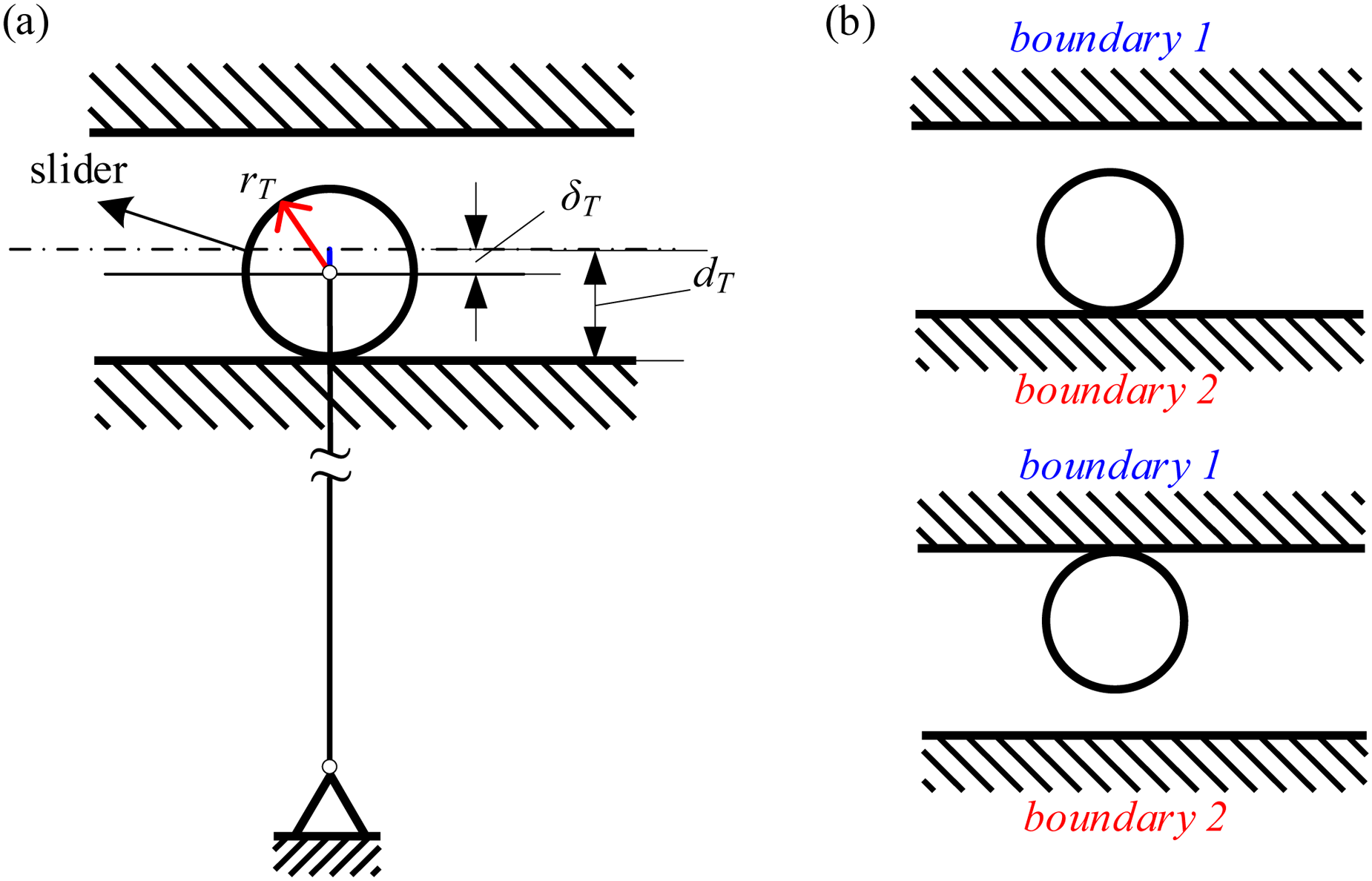
(a) Translational clearance; (b) Contact scenarios between the slider and the guide.
Kinematic model with joint clearance
For ideal joint without clearance, there is only one degree of freedom of the linkage mechanism and the motion is deterministic when an input is given. When clearance is included to the linkage mechanism, other degrees of freedom will be introduced for each joint. Under this condition, the loop closure equation is insufficient to determine the positions of these links. To deal with this multi-degree of freedom problem, the reciprocal screw will be introduced to provide the additional equilibrant equations. So, a brief introduction will be given to the screw theory in this section. According to the screw theory, details will be given to the procedure of how to construct the governing equations to the transmission mechanism. Finally, the FEM model will be conducted as the verification to the proposed procedure of determining the kinematics of the transmission mechanism.
Reciprocal screw
The screw theory, which was developed by Ball in 1900,
37
has been widely applied for kinematics and kinetics analysis for robotics mechanisms in recently years.
38
In kinematics, the reciprocal screw theory will determine the equilibrium condition for a joint,
39
which can be formulated as follows:

For a single loop linkage mechanism, the relations of the joint transmission wrench screw $
w_i
(i
+
1) and externally applied wrench screw $
w
_i(i
+
1) can be given as $
w
_i(i
+
1) = $
w
_(i−1)i + $
w_i
, where i = 2,3…n − 1is the links index and n is the total link number in the single loop linkage mechanism. So, combining the joint transmission wrench screw and the joint equilibrium condition given in Equation (3), a total number of n − 1 scalar equations can be given to determine the unknowns for the positions of the links:

Kinematic model
As shown in Figure 5, there exist 9 joint clearances indicated by a, b, c, d, e, f, g, h, i in one side of the linkage mechanism. The linkage mechanism can be divided into two parts: the slider-crank mechanism and the four-bar linkage mechanism. For clarity, the two parts will be investigated individually with the screw theory. Combining the result of these two parts, the kinematics of the transmission mechanism will be determined finally.
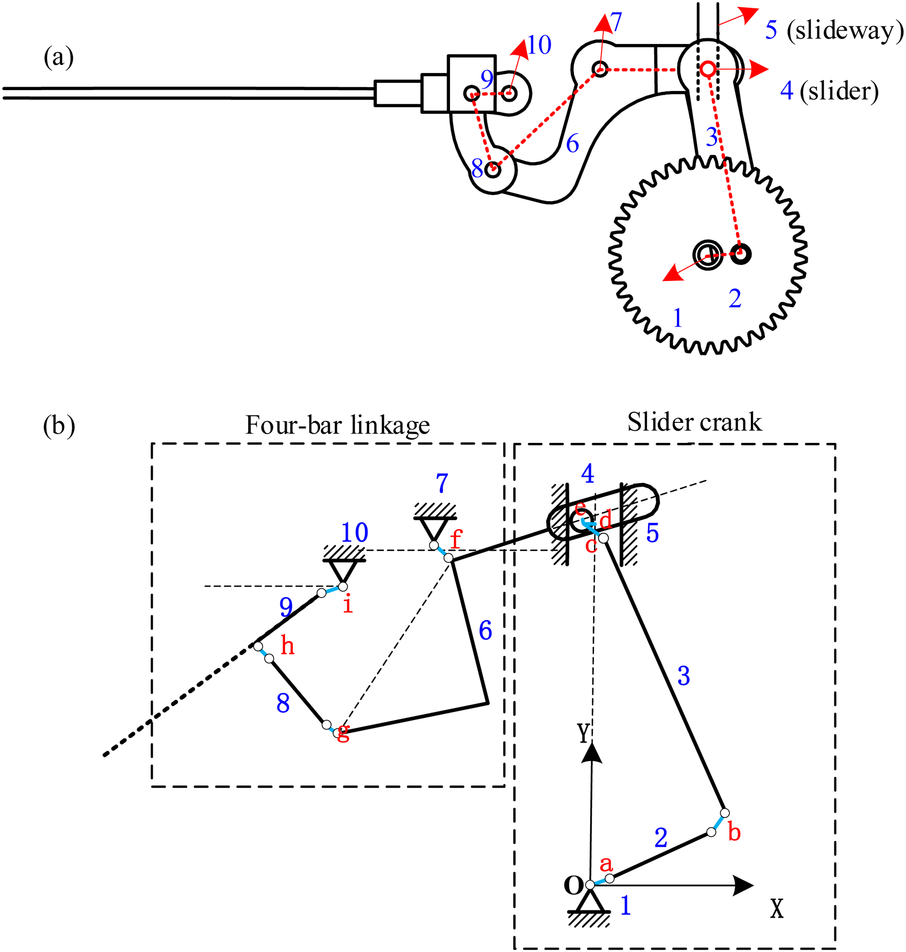
(a) Prototype of the linkage mechanism; (b) Schematic of the linkage mechanism with joint clearance. (1,5,7,10 represent the fixed foundation and the rest number represent the moving parts).
Slider-crank mechanism
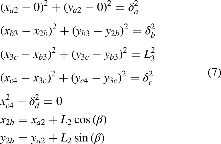
For the slider-crank mechanism, as shown in Figure 6(a), there are four joint clearances a, b, c, d, which have been represented by massless links. Under external forces and inertial forces, all the links are under dynamical equilibrium state. According to the screw theory and Figure 6(b), we can get the reciprocal equations as follows:


Planar slider-crank mechanism with joint clearances and (a) externally applied force;(b) twist screws and wrench screws.
In addition, the constraint equations obtained by the geometric relations are as follows:
Four-bar linkage mechanism
For the four-bar linkage mechanism, as shown in Figure 7, there are five joint clearances e, f, g, h, i. The external forces applied to this mechanism contains the aerodynamics drag Fdrag and the interaction force Fc/2 from the slider. With the inertial forces of these links, the screw theory given in Equation (4) can be used to obtain the dynamical equilibrium equations for all the joints as:


(a) External applied force and (b) twist screws and wrench screws for the four-bar linkage mechanism with joint clearances.
Besides, the constraint equations obtained by the geometric relations are as follows:

Synthesis and solution
Based on the reciprocal screw theory, the dynamical equilibrium equations for the slider-crank mechanism and the four-bar linkage mechanism have been formulated. In this section, we concentrate on searching for the solution of these equations.
First, in this paper, the gear box is deemed to rotate at a constant frequency f, which means β = ω0t (ω0 = 2πf is the angular speed of link 2). The parameters of the linkage mechanism are listed in Table 1. Besides, the inertial force is obtained by the kinetics model without joint clearance,
24
which is proved to be feasible in Section 5. As for the aerodynamic force, the flow mechanisms and the aerodynamic performance of the flapping wing have been extensively explored.40–43 However, utilizing a simplified aerodynamics model will be more efficient to predict the aerodynamic force during preliminary design. In this paper, the quasi-steady aerodynamics model modified by Lee et al.
44
is adopted, which is proved to be feasible for estimating periodic aerodynamics during different flapping motion.24,45,46 The drag is given by the following equations:

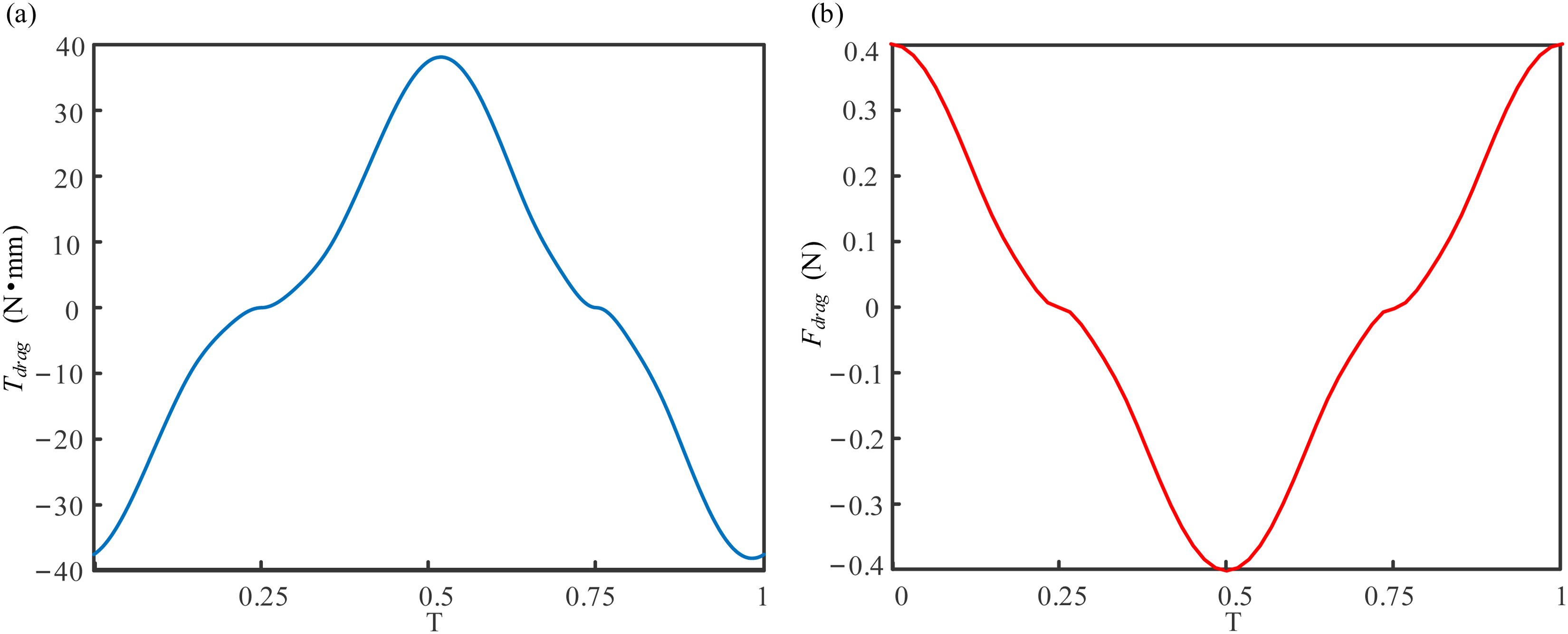
Fdrag and Tdrag estimated by quasi-steady model. (T = 1/f).
Parameters of the linkage mechanism. mj and Jj are the mass and the rotational inertia of component j, respectively. (length in mm, angle in rad, mass in

Besides, the interaction force Fc, which acts as an internal force in the linkage mechanism, can be replaced by the expression as follows:
To summarize, there is a total of 14 unknowns in the slider-crank mechanism: xa2, ya2, x2b, y2b, xb3, yb3, x3c, y3c, xc4, yc4, Tgear, Fx1a, Fy1a, Tz1a. The number of reciprocal equations is 7 and the number of geometric constraint equations is 7. As for the four-bar linkage mechanism, there is a total of 17 unknowns: xf6, yf6, xg8, yg8, x8h, y8h, xh8, yh9, x9i, y9i, γ, Fx45, Fy45, Tz45, Fx7f, Fy7f, Tz7f. The number of reciprocal equations is 10 (keeping in mind that the first equation of Equation (8) contains two scalar equations) and the number of geometric constrain equations is 7. So, there are 31 unknowns in the linkage mechanism, which is equals to the number of equations; that is the equations are solvable in general.
Although the number of unknowns is equal to the number of equations, the solution is not unique. To find the one and only practical solution, additional constraints need to be introduced. For each joint, as shown in Figure 9, the direction of the force that link i applies to link j must be from point Oj to point Oi, where Oj and Oi is the center of the pin of link j and the center of the hole of link i, respectively.
34
Here the contact friction has been neglected. The direction of the contact force can be expressed in mathematics as follows:


Tensile massless link in the clearance.
We can obtain 9 sets of constraints for the 9 joints in the linkage mechanism according to equation (14). Under these constraints, the only practical solution can be realized. Three steps needed when pursuing the practical solution with numerical iteration: 1. Build the kinematics and kinetics model of the linkage mechanism without joint clearance and get the position and force of each link; 2. Based on the condition in step 1, derive the practical solution at time t = 0 for the kinematics model with joint clearance; 3. Taking the practical solution at time t = 0 as initial value, the practical solution at other time can be reached by iteration with a sufficiently small time step. The time step is taken as T/300 in this study.
Model verification
To validate the model proposed above, FEM simulations are performed based on the explicit dynamics.47,48 The FEM model of the linkage mechanism is shown in Figure 10. The geometrical dimensions of the FEM model are the same as those of the kinematic model with joint clearance. To eliminate the influence of the elastic deformation to the flapping angle, an appropriate elastic modulus (2e05Mpa) is employed to the linkage mechanism. All the clearances in the linkage mechanism are set to be the same and two levels of clearance are considered; that is 0.1 mm and 0.05 mm. By setting the proper density to the links, the inertia effect of the mechanism is automatically included in the simulation. The aerodynamical drag is applied to the mechanism through the end link (link 9), as shown in Figure 10, with its value given by equation (11). The simulation model is constructed on Altair Hypermesh platform and solved by LS-DYNA solver. Solid 164 element 49 is used to model the transmission structure and surface contact model 49 is used to define the contact relationships between joints with clearance, where a penalty function is set to avoid contact surface penetration.

FEM model of the linkage mechanism with joint clearances.
Figure 11 shows the flapping angle obtained from the kinematic model and the FEM simulations with and without joint clearance. The flapping angle from the FEM model without clearance is almost identical with the kinematic model without clearance, which proves that the adopted elasticity modulus is suitable to eliminate the effect of flexibility. From the kinematic model with clearance, it clearly shows that the existence of clearance will decrease the flapping angle for certain flapping time and then increase the flapping angle suddenly at some timepoint, where a break happens. The flapping amplitude will be enlarged with joint clearance. Furthermore, the change of the flapping angle is larger if the clearance is larger, and so is the break.

Comparison of flapping angle obtained from kinematic model and FEM simulations.
However, discrepancy do exist between the kinematic model and the FEM simulation, where the kinematic model will give four breaks to the flapping angle whereas the FEM simulations will always give a continuous flapping angle in a flapping cycle. To explain the flapping angle break, we need to go over these breaks in detail. As shown in Figure 12, the wing positions 1, 2, 3, 4 are corresponding to the positions where breaks 1, 2, 3, 4 happens. Based on these four breaks, the flapping angle curve can be divided into four periods. During the period 1, the wing flaps down and the direction of Twing keeps the same (Twing indicates the resultant moment of aerodynamic drag and wing inertia force). However, when the wing keeps flapping down, the aerodynamic force will decrease due to the deceleration of wing. When the wing arrives position 1, the inertia force of the wing will exceed the aerodynamic drag and the direction of Twing changes, which caused the break 1. During the period 2, the wing keeps flapping down and when it reaches the limit, that is, position 2, the link 2 also reaches the limit position. The direction of driving torque Tgear needs to change to maintain the normal operation of the linkage system near the limit position, which causes the break 2. In fact, for the slider-crank mechanism in this FWMAV, when the slider reaches the extreme position, where link 2 and 3 are collinear,

Four periods in a flapping cycle that corresponding to the combination of the direction of Twing and Tgear.
In summary, by checking the transmitted force in these four periods, we find that break 1 and break 3 are induced by the direction change of Twing, whereas break 2 and break 4 are caused by the direction change of driving torque Tgear. In fact, the break is inevitable when the direction of the joint transmission wrench reversed under the massless link assumption. Regardless of the existence of breaks, the kinematic model can nicely capture the influence of the clearance on the flapping kinematics. The results given in Table 2 clearly shows that the flapping amplitude and the mean flapping angle matches nicely between the kinematic model and the FEM model. As the flapping amplitude and the mean flapping angle are the main concerns when referring to the aerodynamic force and the control ability,13,50 the formulated kinematic model can be readily used to unveil the effect of joint clearance on the flapping kinematics.
Flapping amplitude and mean flapping angle obtained from kinematic model and FEM model

Analysis and results
In the previous sections, we have built a kinematic model for the linkage mechanism with joint clearance through screw theory and verified by FEM simulations. In this section, based on the kinematic model, we investigate the effect of the load on the linkage mechanism with joint clearance. Then, we perform kinematic analysis by considering different groups and different sizes of joint clearance.
Load effect
In our previous study, we found that the inertia force of the linkage mechanism is much less than its transmitted loads. 24 To check whether the inertia force of the linkage mechanism can be eliminated, the flapping angle with and without considering the inertia forces of the linkage mechanism are compared by introducing a relatively large joint clearance of 0.1 mm to all joints. As shown in Figure 13(a), the flapping angle obtained by ignoring the inertia force of the linkage mechanism shares almost the same result with the original model. Therefore, the inertia force of the linkage mechanism contributes little to the flapping angle of the FWMAV system with clearance. This justifies the applicability of using the inertial force from the kinematics model without joint clearance in prior section. In fact, the inertia force of the linkage mechanism is much less than the transmitted force as shown in Figure 13(b). In summary, the inertia force of the linkage mechanism can be omitted when analyzing the clearance effect on the flapping motion of the FWMAV.

(A) Flapping angle obtained by the model with and without considering the inertia forces of the linkage mechanism. (b) Transmitted force and inertial force of link 6.
As the inertial force of the links has little effect on the kinematics of the linkage mechanism, the flapping angle will be determined by the direction of the transmitted load only, as the deformation of the linkage mechanism is ignored in this investigation. This indicates that once the break position, i. e. the direction changes of Twing and Tgear, is determined, the flapping angle in a flapping cycle can be obtained. For verification, we assume the aerodynamic force becomes half of its original value while keeping other parameters the same as before. As shown in Figure 14(a) and Figure 14(b), the change of the aerodynamic force only moves the positions of break 1 and break 3, while the flapping angle keeps the same no matter the value of Twing and Tgear that the linkage mechanism bears. This demonstrates the flapping angle is independent on the magnitude of Twing and Tgear. So, to determine the flapping angle with joint clearance, the exact value of Twing is not necessary, which means that we can use Twing = 1 when Twing >0, and Twing = −1 when Twing <0, i.e., Twing = sign (Twing). Besides, the positions of break 2 and break 4 are the same in both cases. This is because that the positions of break 2 and beak 4 are determined by the direction change of Tgear only, which is depended on the geometric parameters of the slider-crank mechanism.

(A) Flapping angle obtained under different aerodynamic force. (b) Driving torque and resultant moment of aerodynamic force and wing inertia force obtained by different aerodynamic force. (Twing and Tgear are obtained by original aerodynamic force, Twing2 and Tgear2 are obtained by half aerodynamic force).
Different joint clearances effect
In this section, different groups and different sizes of joint clearance are considered to reveal the effect of joint clearance on the flapping motion. To differentiate the effect of joint clearances from slider-crank mechanism and the four-bar linkage mechanism, different groups of clearance are considered: 1) joint clearance in the slider-crank mechanism (joint a,b,c,d), 2) joint clearance in the four-bar linkage mechanism (joint e,f,g,h,i), 3) all joint clearance. Besides, different sizes of joint clearance are considered in each case. Considering that the transmission mechanism of the FWMAV may be fabricated by 3D printing (typical resolution 0.1 mm) or by injection molding (resolution 0.02–0.05 mm), clearance size 0.1 mm and 0.05 mm are adopted in this section. The details are listed in Table 3.
Clearance groups and sizes for different cases.

To study the influence of different joint clearances on the flapping angle, we compare the flapping angle obtained from case 1, 3, 5 with the ideal case without clearance. As shown in Figure 15(a), the biggest deviation of the flapping angle from the ideal curve are located at the maximum or the minimum of the flapping angle for all the cases investigated. Meanwhile, the discrepancy between the case 5 and ideal curve is always the largest and the discrepancy between the case 1 and the ideal curve is always the least. This indicates that more clearances always induce larger deviation and the joint clearances located at the four-bar linkage mechanism matter more on the flapping angle deviation than these located at the slider-crank mechanism. The position of clearances shows different contribution to the flapping angle deviation. Interestingly, break 2 and break 4 disappear when the joint clearance of the slider-crank mechanism is eliminated, which proves that break 2 and break 4 are only associated with the slider-crank mechanism. These results are also valid for other clearance sizes as shown in Figure 15(b). In addition, it can be found that larger joint clearances will cause larger flapping angle deviation.

Flapping angle obtained from different cases of joint clearance that corresponding to Table 3.
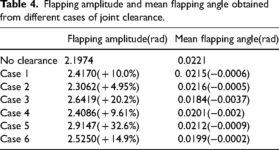
For a FWMAV, the flapping amplitude and the mean flapping angle are the main concerns because they determine the aerodynamic force and the control ability.13,50 The flapping amplitude and the mean flapping angle of each case are shown in Table 4. It can be seen that the joint clearance causes a significant deviation to the flapping amplitude, while it introduces a little deviation to the mean flapping angle. Taking case 6 for example, each joint clearance is set to 0.05 mm, which is almost two orders of magnitude smaller than the length of the shortest link; that is link 2. However, the deviation of flapping amplitude caused by joint clearance is 0.3276 rad, which is almost 15% the original flapping amplitude. This demonstrates the importance of revealing the effect of joint clearances of transmission mechanism to the flapping motion of the FWMAV.
Flapping amplitude and mean flapping angle obtained from different cases of joint clearance.
Besides, to uncover the sensitivity of the flapping amplitude to the joint clearance at different position, each clearance in the linkage mechanism is analyzed individually. As shown in Table 5, clearance a, b, c, e, g, h, i almost share the same sensitivity to the flapping amplitude. The clearance f matters more than the other clearances while the clearance d contributes least to the flapping amplitude. So more attention should be paid to clearance f when designing the transmission mechanism of FWMAV.
Flapping amplitude obtained when individual clearance considered. (clearance size = 0.1 mm)

Discussion and conclusion
In this study, we investigated the effect of joint clearance on the kinematics of the flapping wing by assuming that the gearbox rotates at a constant rate. However, the real transmission mechanism of FWMAV can hardly maintain this state. As has revealed in this work, the inertia force of the transmission mechanism shows little contribution to the contact state of these joints with clearance, whereas the sign of the gear torque Tgear and the wing drag torque Twing determines the contact state uniquely. So, as variation of the rotate rate of the gearbox will surely influence the evolution of the gear torque Tgear and the wing drag torque Twing, the contact state of these joints needs to be determined with the corresponding torques. The natural consequence is that the positions of the breaks will change if the rotate rate of the gearbox differs from the constant one.
When designing a FWMAV, most researchers treated the transmission mechanism as the ideal one, where the structural flexibility and joint clearance are fully ignored. So, the adjustment of the transmission mechanism through extensive experiments are always needed, which is very time-consuming.20,23 In this study, based on the concept of massless link and the reciprocal screw theory, a kinematic model of the transmission mechanism with joint clearance is established. According to the model, the effect of joint clearance on the flapping motion of FWMAV is revealed in detail, which could provide helpful instructions on the preliminary design of transmission mechanism. For example, among all those clearances, the clearance at joint f needs to be examined first, as it matters most on the flapping amplitude. Besides, the joint clearance not only influences the kinematics of the transmission mechanism, but also induces energy dissipation and lowers transmission efficiency,29,51,52 which deserves more concern in the further study.
To conclude, a kinematic model of transmission mechanism with joint clearance for a FWMAV is proposed and validated by FEM simulations. The kinematic model is based on the concept of massless link and the reciprocal screw theory, where the non-uniqueness of the solutions of the model can be well addressed when introducing the constraint that the massless link can only bear tension load. The effect of load and joint clearance on the flapping motion are also investigated and analyzed. The result shows that the inertia force of the linkage mechanism can be eliminated and the sign of Twing other than its magnitude matters when determining the kinematics of the transmission mechanism with joint clearances, which will largely simplify the settlement of the kinematic model. Moreover, joint clearances can either increase or decrease the flapping angle during a flapping cycle and their effect to the kinematics of the transmission mechanism is regulated by the joint position and the clearance magnitude. Besides, joint clearances will significantly affect the flapping amplitude of the wing whereas contribute little to the magnitude of the mean flapping angle.
Footnotes
Acknowledgments
This research was primarily supported by the National Natural Science Foundation of China [Grant numbers 12072013].
Declaration of conflicting interests
The author(s) declared no potential conflicts of interest with respect to the research, authorship, and/or publication of this article.
Funding
The author(s) disclosed receipt of the following financial support for the research, authorship, and/or publication of this article: This work was supported by the National Natural Science Foundation of China, (grant number 12072013).