
Abstract
A practical method for mobility analysis of mechanisms is presented in this article, which is based on the screw theory and the topology structure of mechanisms. The proposed method can be summarized as one core principle and two key techniques. The core principle is that the series connection of kinematic pairs is equivalent to the superposition of corresponding degrees of freedom, and the parallel connection of kinematic pairs is equivalent to the superposition of corresponding constraints. The first key technique for analyzing the mobility of mechanisms is to correctly identify the series and parallel connection relationship between all kinematic pairs, that is, the mechanism topology structure. Another key technique is transforming the screws and reciprocal screws from local coordinate systems to the global coordinate system. First, the above-mentioned method is presented in theory. Then, several examples are analyzed using it, which validate its effectiveness and universality.
Introduction
Mobility is a fundamental structural parameter which reflects the most essential kinematic features of a mechanism. International Federation for the Promotion of Mechanism and Machine Science (IFToMM) 1 terminology defines the mobility or the degrees of freedom (DOFs) as the number of independent coordinates needed to determine the configuration of a kinematic chain or a mechanism. Thus, mobility analysis is always the first job for engineers when they intend to design or operate a mechanism. Because it is difficult to find a method with both simplicity and universality, the discussion about how to calculate the mobility has lasted for more than 100 years. In the era of planar mechanisms, the Grübler–Kutzbach (G-K) criterion2,3 was successfully used to analyze the mobility of mechanism. However, after the emergence of some complex spatial mechanisms, especially those spatial parallel mechanisms, whose mobility calculation is far more difficult than that of serial mechanisms, G-K criterion exposed the limits of its power. 4
In the past decades, dozens of methods have been proposed to make up for the deficiency of G-K criterion. These methods can be classified into two main categories: the first category consists of those concise formulas for a quick calculation of mobility,5,6 and this kind of approaches only refer to the number and type of components and kinematic pairs of a mechanism; the other category includes those methods based on some complex mathematic skills, such as building the kinematic constraint equations and their rank calculation, calculating the nullity of the Jacobian matrix of a mechanism, utilizing group theory and Lee algebra to analyze kinematic chains, and so on. Nonetheless, the former kind of methods is so concise that they could not take all factors into account and thereby just suits to few specific mechanisms, and those methods that fall into the latter category are too complex to be grasped by engineers. Besides the above methods, Hunt 7 and Waldron and Kinzel 8 first introduced the screw theory to deal with this problem, but they did not present an universal approach to determine the order of the mechanism, which is a key parameter for their method.
Huang et al.9,10 introduced the reciprocal motion screw of a kinematic pair to define the constraints caused by it. They redefined the order of a mechanism and the concept of redundant constraint. Based on these definitions, they developed a systematic methodology, the modified G-K criterion, for mobility analysis by utilizing the reciprocity between motions and constraints in screw theory. To facilitate users to successfully analyze the mobility of any mechanism, four key techniques were provided by them, that is, the identification of redundant constraint, the choice of reference frame, the judgment of the instantaneous/full-cycle freedom, and the disposal of the closed-loop chain in limb. The effectiveness and universality of their methodology have been validated by numerous paradoxical mechanisms, including those famous classical mechanisms and some modern parallel ones. However, two of the four techniques, that is, transforming the screws from local frame to the global frame and substituting the closed-loop chain with certain generalized kinematic pair, heavily depend on users’ individual experience and perceptual observation, which prevents its programmability and its application of automatic mobility analysis. Besides, their method is only able to determine the number of DOFs for a mechanism. Neither the type nor the direction of those DOFs can be determined.
Zhao et al.11–13 also utilized the reciprocal screw theory to deal with the mobility problem of parallel mechanisms. First, they pointed out that the DOF of a mechanism system should be different from the DOF of the end effector. Then, they proposed that the end effector’s DOF should cover three main attributes, namely, the number, type, and direction, which are more helpful than just the number data when analyzing and designing the mechanisms. Finally, they introduced the concept of constraint spaces spanned by the maximum linearly independent set of constraint screw sets of all limbs to describe the constraint situation. Accordingly, the orthogonal complement subspace of the constraint spaces is the free motion space, whose dimension denotes the number of end effector’s DOFs, and its component screws denote the type and direction of end effector’s DOFs. They tried to apply the union of reciprocal screws to represent the whole constraints exerted on mechanisms. They developed Huang et al.’s method very well and offered a simpler approach to carry out mobility analysis, with which we are able to obtain more concrete DOF information. However, those parallel or hybrid limbs should be replaced with pure series limbs before their analysis, which to some extent increases the workload of mobility analysis. In addition, when calculating the reciprocal screws of all limbs under the global frame, Zhao et al. did not provide a more convenient approach in mathematics but just solved them based on their global coordinates directly.
To solve the above-mentioned limitations of Huang et al.’s and Zhao et al.’s methods, a simple and universal method for mobility analysis of mechanisms is put forward in this article. The proposed method is based on the screw theory and the topology structure of mechanisms, and it mainly consists of one core principle and two key techniques. The one core principle is that the series connection of kinematic pairs is equivalent to the superposition of DOFs caused by corresponding pairs, and the parallel connection of kinematic pairs is equivalent to the superposition of constraints caused by corresponding pairs. According to the screw and reciprocal screw theory, the DOFs of a kinematic pair can be denoted by its motion screw, and the constraint brought by a kinematic pair can be expressed with its reciprocal motion screw. Thus, the DOFs of a mechanism with series kinematic pairs can be obtained with the union of corresponding screw sets, and the constraints of a mechanism with parallel pairs can be obtained with the union of corresponding reciprocal screw sets.
For most parallel mechanisms, there always exist both series kinematic pairs and parallel kinematic pairs. Therefore, the first key technique for analyzing the mobility of mechanisms is to correctly identify the series and parallel connection relationship between all kinematic pairs, that is, the mechanism topology. Another key technique is transforming the screws and reciprocal screws from local coordinate systems to the global coordinate system with rigorous mathematics derivation. This kind of transformation for screws has been considered as impossible by previous researchers. 10 This technique guarantees the convenience and simplicity of writing out screws/reciprocal screws of pairs at different positions and orientations in the global coordinate system with rigorous mathematics deduction.
This article is organized as follows: section “Introduction” provides the introduction. In section “Basic theories of the proposed method,” three basic theories of the proposed method are presented: first, the basics of screw theory and reciprocal screw theory, especially the method about how to transform the screws and reciprocal screws from a local coordinate system to the global coordinate system, are described; second, the core principle we mentioned above is explained based on the screw and reciprocal screw; third, the normal topology structure of mechanisms is analyzed. In section “Mobility analysis of some typical mechanisms,” some typical paradoxical mechanisms are analyzed with the proposed method, whose effectiveness and universality are compared with other methods. At the same time, some observations and recommendations about mobility analysis will also be provided. Section “Conclusion” presents the conclusion and outlook of this work.
Basic theories of the proposed method
Basics of screw and reciprocal screw theory
Based on the screw theory,6,7 a common screw can be written as

where
When

Coordinate transformation of a screw between two frames.
According to the screw theory,
7
a screw
For any two screws,

where “○” is the symbol of making reciprocal product between two screws.
The physical meaning of a reciprocal product is the virtual work produced by a wrench
Assume the screw expression of AB in Figure 1 under frame P-xyz is

where
Then, we can rewrite the screw of AB under the global frame as follows

where
Assuming the rotation matrix between the coordinate systems P-xyz and O-XYZ is


Thus

which can be further organized into matrix format as follows14,15

where
Equation (5) is the formula for transforming a screw between the two different coordinate systems. However, during the practical application of mobility analysis, if we just transform those local screws to the global frame and then calculate their reciprocal screws under this frame, we will actually feel it is still very hard to write out those reciprocal screws directly. In fact, the reason for building various local frames for different limbs is that it is easier to directly write out those screws of kinematic pairs based on their own frame, and we are also able to control their form to be as simple as possible. Accordingly, the reciprocal screw set of these screws can also be calculated easily. Therefore, an ideal method is to first figure out the reciprocal screws under local frame and then transform it to the global frame.
Given that two screws
where
Thus

Now, we can transform these two screws to the global frame O-XYZ based on equation (5) and rewrite them as follows


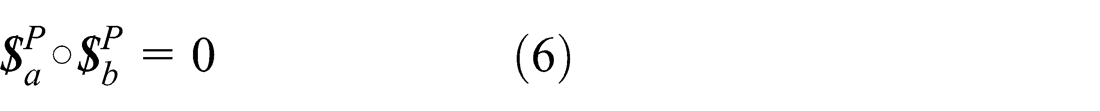
Then, the reciprocal product of

According to basic geometrics knowledge, when three vectors are transformed with an orthogonal matrix simultaneously, the mixed product of them is preserved, that is, if
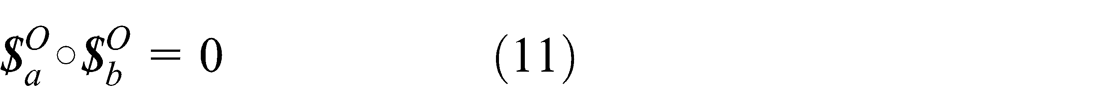
Equations (5), (6), and (11) demonstrate that (1) the reciprocity relationship between two line vectors is independent of the position and orientation of the coordinate systems they are in, and (2) the reciprocal line vector screw can be transformed to the global frame using equation (5), and it will be reciprocal to the counterpart transformation form of the original line vector, namely

Analogously, for a couple kind of screw/reciprocal screw, the transformation of it can also be conducted with equation (12), and the corresponding derivation is similar to the above deduction process of line vector kind of screw/reciprocal screw. Comparing equation (5) with equation (12), it is not hard to see that the transformation for screws and reciprocal screws actually share the same transformation rules.
The core principle of mobility analysis
The topology schemes of two basic connection types among kinematic pairs are shown in Figure 2. The relationship between mechanism mobility and mechanism topology is discussed as follows.
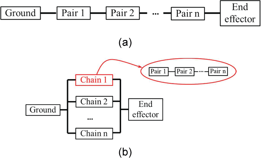
Two basic connection types among kinematic pairs in mechanics: (a) series connection of kinematic pairs and (b) parallel connection of kinematic pairs.
The series connection of kinematic pairs
Based on Zhao et al.’s theory, 13 the general velocity of the end effector shown in Figure 2(a) can be expressed as a Plücker column vector

where
Equation (13.1) indicates that in the fixed coordinate systems, the velocity screw of the end effector, which belongs to a rigid-body system composed of n general revolute joints in series, can be equivalent to a linear combination of all the motion screws in the kinematic chain. The linear coefficients describe the amplitude of the angular speed of the corresponding general rotational joints. It is worth noting that the general revolute joints can be prismatic joints (P), revolute joints (R), universal joints (U), and spherical joints (S) in practice, and the general angular speed includes both linear velocity and angular speed. Thus, the motion ability of a rigid-body system can be obtained by analyzing the motion screw matrix of the kinematic chain. Furthermore, because all motion information of the end effector is included in the motion screw matrix, we are able to regard the series connection of kinematic pairs as the superposition of motion screws caused by corresponding pairs in the kinematic chain.
The parallel connection of kinematic pairs
Based on the force balance condition of Newton mechanics, the whole constraint force of the end effector shown in Figure 2(b) can easily be expressed as a Plücker column vector

where
Equation (13.2) indicates that under the fixed coordinate systems, the whole constraint force of the end effector can be equivalent to a linear combination of all the constraint screws of limbs connected to it. The linear coefficients describe the amplitude of the torque of the corresponding general rotational joints. It is worth noting that the general torque includes both force and torque in practice. Thus, the constraint status of a rigid-body system can be obtained by analyzing the constraint screw matrix of it. Furthermore, because all constraint information of the end effector is included in the constraint screw matrix, we are able to regard the parallel connection of kinematic pairs as the superposition of constraint screws caused by corresponding pairs.
In summary, we are able to obtain the motion screw set and the constraint screw set of end effectors in Figure 2. Assume the motion screw of pair i shown in Figure 2 is
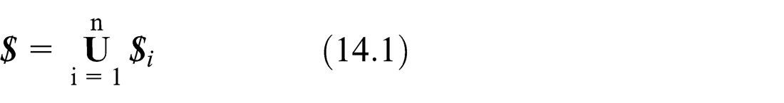
Correspondingly, the constraint screw of the end effector in Figure 2(b) can be written as

If we want to obtain the concrete motion screw set of the end effector in Figure 2(b), we just need to calculate the reciprocal screw of
Various kinds of mechanism topologies
Just like various kinds of hybrid circuits in electrics, there are also a great number of mechanisms with complex connections among their kinematic pairs. Besides the two basic kinds of connection topology shown in Figure 2, there are various kinds of mechanisms with complex connection topologies. 17 Three typical mechanism topologies are shown in Figure 3, where type 1 is the common topology of parallel mechanisms with several serial limbs, such as the Delta mechanism, the Tricept mechanism, and the H4 mechanism. Type 2 denotes a mechanism with several parallel parts in series, for example, there is an ultra-precise mechanism with double Stewart platforms in series for precision adjustment; the topology of type 3 is usually applied in hybrid machine tools, for example, a five-axis milling machine with X-Y DOFs and a parallel Z3 head in series.

Three typical mechanism topologies: (a) type 1 connection topology, (b) type 2 connection topology, and (c) type 3 connection topology.
Assume the motion screw of pair t shown in Figure 3 is


The general process of mobility analysis for a mechanism
If we want to accurately analyze the mobility of a mechanism, the following three main steps are needed:
The first key task is to identify the connection topology between different pairs of it. The topology graph plays a role as guidance for the execution of the core principle.
Then, we should flexibly carry out the motion screw of the end effector with the union of screws or reciprocal screws of every kinematic pairs based on the core principle. During this process, the second key technology about screw transformation between local frames and the global frames will be used frequently.
Finally, according to the motion screw of the end effector, we are able to acquire the following mobility information of this mechanism: the number, type, and direction of DOFs and the detailed coupling relationship among different DOFs.
Mobility analysis of some typical mechanisms
To present the concrete procedure of the proposed method and validate its feasibility, several typical complex spatial mechanisms are analyzed with it in this section.
The 3PRS mechanism
The 3PRS architecture is a well-known mechanism in industry, the most successful application of which is the Sprint Z3 machine head. As we all know, 3PRS has two rotation DOFs around x- and y-axes, respectively, and one translation DOF along the z-direction. Now, let us validate this conclusion with our proposed method.
The schematic diagram of a 3PRS parallel mechanism is given in Figure 4(a). The moving platform is symmetrically connected to the base with three identical limbs. Each limb consists of an actuated prismatic joint, a revolute joint, and a spherical joint in series. Due to the inherent constraint caused by R joint, the motion of each limb is limited in its own plane, as shown in Figure 4(a). Evidently, the topology of 3PRS belongs to the type 1 connection, and it is better to first deduce the reciprocal screw of each limb. Then, as long as we figure out the union set of three limbs’ reciprocal screw and compute the reciprocal screw of it, we will obtain the motion screw of the moving platform. To analyze the limbs conveniently, three local coordinate systems are built on their P joint, and the direction of them is illustrated in Figure 4(a). Because of their symmetry, just one limb should be analyzed here. Limb 1 and its own coordinate system A1-x 1 y 1 z 1 are shown in Figure 4(b), from which we can obtain the twist screws of pairs in limb 1 as follows


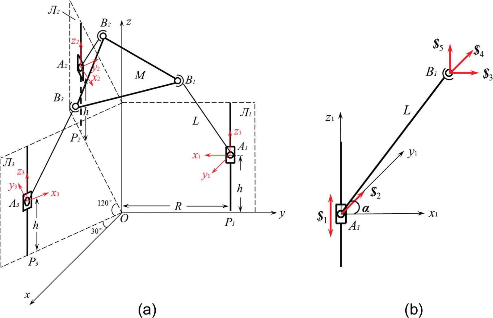
The 3PRS mechanism: (a) sketch of a 3PRS mechanism and (b) sketch of limb 1.
Then, we are able to write out the reciprocal screw of the above five screws under the frame A1-x 1 y 1 z 1 as

whose
It is easy to know that the rotation matrix between frame A1-x 1 y 1 z 1 and the global frame O-XYZ is

and the translation vector
Then,

Similarly, the rotation matrixes and the translation vectors between frames A2-x 2 y 2 z 2, A3-x 3 y 3 z 3, and the global frame O-XYZ are

respectively.
Correspondingly,
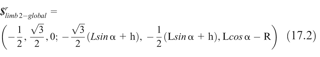

Thus, according to equation (16.1), the motion screw set of the end effector is equal to

where (a) denotes a translation DOF along the z-direction, (b) denotes a revolution DOF around the x-axis with parasitic motion along the y-direction, and (c) denotes a revolution DOF around the y-axis with parasitic motion along the x-direction. Obviously, the mobility analysis results are totally consistent with the actual features of 3PRS mechanism.
A decoupled 2R1T mechanism without parasitic motion
The 2R1T mechanisms are normally applied in manufacturing equipment. However, as we have seen in section “3PRS mechanism,” parasitic motion always occurs for this kind of mechanism. Because parasitic motion will lead to complex kinematics which impede the improvement of the end effector’s accuracy, require real-time compensation which cause complexities in controlling the machine, and increase difficulties in calibration, 18 some researchers try to synthesize decoupled 2R1T mechanisms without parasitic motion. The architecture demonstrated in Figure 5(a) is such a decoupled 2R1T mechanism, whose moving platform is on the bar OC3. This mechanism is proposed by Xie et al., 19 who have already proved that it owns one translation DOF along the z-direction and two rotation DOFs around x- and y-axes, respectively. Moreover, these DOFs are independent of each other, that is, they are decoupled. After analyzing this mechanism carefully, we are able to draw its topology graph as shown in Figure 5(b). It is interesting to see that there are three limbs in this mechanism, but they are not directly connected in parallel: first, limb 1 parallel connects limb 2; then, they connect to a revolute joint in series and form an integrated limb; finally, the integrated limb and limb 3 connect to the moving platform together.

A decoupled mechanism with 2R1T DOFs: (a) sketch of this mechanism and (b) topology of this mechanism.
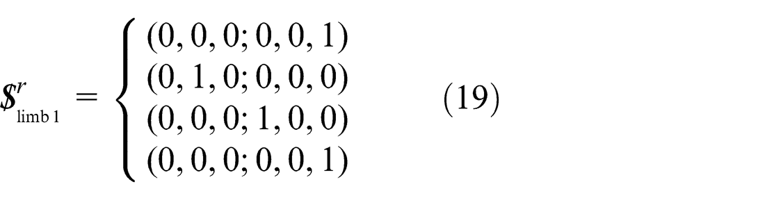
When the global coordinate system O-xyz is set in the position and orientation as shown in Figure 5(a), the twist screws of all limbs can be easily expressed. Thus, it is unnecessary to build local frames anymore. Based on the position and orientation of pairs, the screws of limb 1 can be obtained as


Then, the constraint screws of limb 1 are
Correspondingly, the screws of limb 2 can be written as


And the constraint screws of limb 2 are

Therefore, the public motion screws of limb 1 and limb 2 can be expressed as

The two screws of
Furthermore, we should study the motion screw set of limb 3


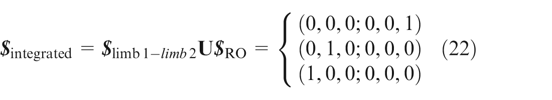
It is not hard to see that the rank of this screw set is 6, which means that there does not exist reciprocal screw for it, that is, limb 3 provides no constraints to the end effector. Hence, the motion screw set of the end effector

which indicates three DOFs: one translation DOF along the z-direction, one rotation DOF around the y-axis, and one rotation DOF around the x-axis. Because there is only one element in each screw, every DOF is completely independent of other DOFs, namely, there is no parasitic motion caused by it.
The mobility analysis results are totally consistent with actual features of the decoupled mechanism. Considering these two 2R1T mechanisms in sections “3PRS mechanism” and “Decoupled 2R1T mechanism without parasitic motion” together, we can draw a conclusion that besides the number, type, and direction of mobility, the proposed method in this article is able to produce the detailed coupling relationship among different DOFs.
The 4PUU mechanism
The 4PUU mechanism is an interesting counterexample proposed by Zhao et al., 11 who pointed out that all previous methods lead to a wrong result when they are applied to analyze the mobility of this mechanism. They successfully solved this problem with their own theory. However, when transforming the reciprocal screws of a limb in local frame to the global frame, they did not provide a rigorous approach with mathematics deduction. They just judged the physical meaning of inverse screws in local frame and then deduced that its counterpart in the global frame depended on personal observation, which to some extent makes their theory so perceptual. Here, we will analyze the same mechanism with our method, which is completely based on mathematical derivation.
As we can see from Figure 6(a), there are four limbs suspended on two guides in the architecture. Every limb consists of a P joint and two universal (U) joints, where the P joint is usually selected as the actuation. Four local coordinate systems are built as shown in Figure 6(a), which guarantees that the relative positions and orientations between limbs and their local frames are identical. Then, we just need to study one limb of them and then transform it with four different rotation matrixes.

The 4PUU mechanism: (a) sketch of the 4PUU mechanism and (b) sketch of limb 1.
The local coordinate system of limb 1 is demonstrated in Figure 6(b), from which we can achieve five motion screws of limb 1 under o 1-x 1 y 1 z 1 as follows


Corresponding reciprocal screw of the above screws can be expressed as

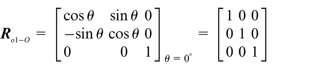
The rotation matrix between frame o 1-x 1 y 1 z 1 and the global frame o-xyz is

Thus,

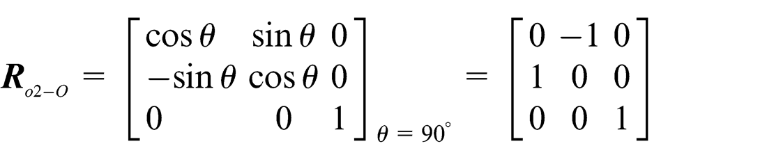
Similarly, the reciprocal screws of other three limbs under the global coordinate system can be derived as


and
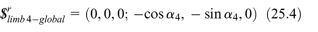
Therefore, according to equations (25.1)–(25.4), the motion screw of the end effector is generally equal to

which indicates three translation DOFs along x, y, and z-axes, respectively, and a rotation DOF around the z-axis. All four DOFs are independent of others, and there are no coupling relationships among its different DOFs.
It is worth noting that there will exist one more screw in equation (26), when

or

This situation is actually a singularity phenomenon, and it can be avoided by adjusting the kinematic parameters.
The orthoglide mechanism
The orthoglide mechanism 20 is presented in Figure 7(a), from which we can see that it consists of three limbs, and each limb includes a four-bar parallelogram loop. Corresponding local coordinate systems of three limbs are built as shown in Figure 7(a), which guarantees that every limb is identical. To study the four-bar parallelogram loop in limb 1, a local frame C 1- u 1 v 1 w 1 of it is built, as shown in Figure 7(b).

The Orthoglide mechanism: (a) sketch of the orthoglide mechanism and (b) sketch of the four-bar parallelogram loop in limb 1.
It is not hard to obtain the motion screws of two sublimbs of the parallelogram loop. For limb α, we have


where (0, yd 1, zd 1) is the coordinates of D1 under the coordinate system C 1- u 1 v 1 w 1.
For limb β, we obtain


where l is the length of C1E1.
Thus, the motion screw of the parallelogram mechanism in the local coordinate system C 1-u 1 v 1 w 1 is

Since the rotation matrix between C1 -u1v1w1 and o1 -x1y1z1 is equal to

we can transfer

where a = zd1 sinθ 1, b = zd1 cosθ 1, c = −yd 1.
Furthermore, all motion screws of limb 1 under the frame o 1-x 1 y 1 z 1 can be written as


Corresponding constrained screws of limb 1 can thereby be expressed as

Due to the fact that

Moreover, the rotation matrixes between o 1-x 1 y 1 z 1, o 2-x 2 y 2 z 2, o 3-x 3 y 3 z 3, and O-xyz are, respectively, equal to

Based on these rotation matrixes and equation (15), the constraint screws of three limbs under their own local coordinate system can be transferred to the global coordinate system and be expressed as


Finally, the motion screw of the moving platform can be derived as

which suggests that the mechanism has three independent translational DOFs along x-, y-, and z-axes, respectively.
The orthoglide mechanism has also been analyzed by Huang et al., 10 who first substituted the parallelogram loop with a generalized translational pair that can translate on plane C1D1F1E1, and then, they transferred the reciprocal screws of limb 1 under its local frame to the global frame based on perceptual experience rather than rigorous mathematics derivation. The dependency of Huang et al.’s method on perceptual experience makes it hard to spread widely. Besides, Huang just calculated the number of DOFs for the mechanism and the information about DOFs’ type, direction and the coupling relationship between each other. However, all these key information about DOFs of the orthoglide mechanism is easily obtained with our proposed method.
Comparison among four mobility analysis methods
According to the above analysis, we can compare the mobility analysis results among four different methods as shown in Table 1.
Comparison among four mobility analysis methods.

G-K: Grübler–Kutzbach; DOF: degree of freedom.
Symbol “–” means corresponding information cannot be obtained with counterpart methods. R x and T x , respectively, mean a rotation DOF around the x-axis, a translation DOF along the x-axis, and the like.
From Table 1, we can see that the classical G-K criterion usually causes wrong mobility results when analyzing spatial parallel mechanisms. Although all of the last three methods are able to yield right DOF number, only Zhao et al.’s method and the proposed method can provide the detailed coupling relationship among different DOFs. Moreover, the proposed method is also the simplest one among the last three approaches, due to the fact that it just depends on a simple execution principle and based on some fundamental geometric and algebraic knowledge.
Conclusion
The method for mobility analyzing using one core principle and two key techniques was introduced in this article. The principle reflects the inherent difference between series connection and parallel connection of kinematic pairs very well. The first key technique is to correctly identify the mechanism topology. Another key technique provides a series of universal mathematics formula for transferring the screws and reciprocal screws in local coordinate systems to the global coordinate system.
Overall, the proposed method has the following features:
Rigorousness. The whole methodology is totally based on rigorous mathematics derivation, especially according to the theory of screw and reciprocal and the theory of mechanism topology.
Programmability. Since the proposed method is totally based on mathematics derivation and it is completely irrelevant with human experience, the method can be conveniently implemented to a computer program for automatic mobility analysis of mechanisms. This is one of our works in the future.
Effectiveness. Several practical examples, all of which are complex spatial mechanisms, are successfully analyzed with the proposed method. These examples validate the feasibility and effectiveness of this method.
Universality. The universality of this method is ensured by the rigorous theoretical basics stated in sections “Basics of screw and reciprocal screw theory,”“Core principle of mobility analysis,” and “Various kinds of mechanism topologies” and the standard and general analysis process stated in section “General process of mobility analysis for a mechanism.”
Completeness. All attributes of DOFs, such as the number, type, direction, and the detailed coupling relationship among DOFs, can be obtained directly using the method proposed in this article.
Footnotes
Academic Editor: Yaguo Lei
Declaration of conflicting interests
The author(s) declared no potential conflicts of interest with respect to the research, authorship, and/or publication of this article.
Funding
The author(s) disclosed receipt of the following financial support for the research, authorship, and/or publication of this article: The investigation in this article is supported by National Science Fund for Distinguished Young Scholars (grant no. 51225503).