
Abstract
An assessment of 3D-printed span-change structures is presented for determining suitability of the technology to small unmanned aerial vehicles. Materials and manufacturing technologies were used with an emphasis on near term applicability with design trades between the aerodynamic performance and structural response. Aerodynamic performance was assessed on three wind tunnel models varying span (432, 600, and 762 mm), wind speed (Reynolds numbers 18,000, 36,000, and 71,000), additive manufacturing print build plane and camber, quantifying structural response as the resulting shape during aerodynamic loading. Each model displayed increasing compliance as span increased with wing-tip displacement on the order of 50, 100, and 200 mm with various degrees of sweep and twist. Models generated excess lift at Re = 71,000 indicating potential flight demonstration of the technology with a lift to drag improvement of up to 97% at maximum wing extension.
Introduction
Flight adaptation to varying environmental conditions or mission segments can provide optimal performance given a reconfiguration of shape,1–4 but mechanical complexity and energy use often limit practical implementation. Adaptation research has drawn inspiration from ornithology as birds are able to dive at high speeds, can soar at low energy, and have exceptional range5,6 as well as from entomology in that some insects can fold their wings generating extreme aspect ratio (AR) changes. 7 Research has sought to imitate shape changes from nature developing exotic materials, structures, and actuation mechanisms to mimic bone and musculature. Recent promising work has explored the use of shape memory alloys or shape memory polymers,8–11 in addition to electrically or magnetically sensitive materials12,13 to control aerodynamic shape by adapting structural stiffness. When considering very large changes in volume, the design problem centers around developing a structure that is compliant for the purposes of adaptation, while remaining stiff for the purpose of aerodynamic efficiency and vehicle control. 14
For small fixed wing unmanned air vehicles (UAVs) flying at low Reynolds number, aerodynamic performance is usually degraded compared to higher Reynolds number vehicles. However, given that the effects of changing wing span or AR are likely to be the same at all Reynolds numbers, span change is likely to improve aerodynamic performance. An extended wing span during take-off, landing, and low-speed cruise can be useful in order to enhance the lift and fuel efficiency at low flight speeds, while a reduced wing span is advantageous for fast and highly maneuverable flight. 15 Through the development of a variable span wing, UAVs can benefit from the advantages of both short and long wings as needed by the varying phases of flight. 16 Span changes have historically been actualized by non-traditional structural arrangements such as auxetic lattices, where the Poisson’s ratio of the structure is zero or negative or through the use of cable truss systems.17,18 Zero or negative Poisson’s ratio creates situations where the wing span or chord can increase without the other changing, or they both could increase in exchange for structural compliance. Added degrees of compliance are accounted for with auxiliary stiffening members which carry the aerodynamic loading transferred from a soft skin. 19 Larger aircraft with higher aerodynamic loading typically use telescoping shell segments because soft skins will displace unreasonable amounts. 20 Other shape changes like camber do not usually require soft skins because the adaptation does not require large tensile strain, instead altering the coefficient of lift by buckling skin into a desired shape through changes to global radius of curvature applied bending strain.21,22
The objective of the current work is to assess the applicability of additively manufactured (AM) span-change structures, specifically focusing on expanding the idea of internal telescoping segments with a soft skin. Three wind tunnel models will be presented with explanations for material selection, AM method, and interior geometry arrangement. The structures will be assessed in terms of weight, stiffness, and aerodynamic performance to determine if soft-skinned span-change vehicles can be made viable by the use of AM technology. Results will be discussed with a focus on span-change performance and the penalties associated with reducing mass-stiffness as a function of the AM build, camber, and AR for low Reynolds number flight.
Methodology
Span extension
Multiple researchers have considered various types of morphing previously including span, twist, camber, sweep, chord length, and wing thickness. 23 These prior efforts have included both numerical and experimental efforts 24 with each type of morphing known to have its own set of advantages and disadvantages. 25 For example, while Justin et al. 26 were able to show significant airfoil morphing using SMA wires, the number of wires and complexity of the system increased significantly compared to their preliminary optimization process. 19
Of all these potential types of morphing, it has been previously shown by Joshi et al. 3 that for a 2350 lb UAV traveling at speeds up to M = 0.5, the greatest aerodynamic benefits can be obtained through large-scale shape change, i.e. span, chord, and sweep morphing. As the UAV size, weight, and maximum speed are decreased, it was found that varying the span was one of the most effective means to reduce drag and optimize spanwise lift distribution while maintaining constant lift. 27 The design space for any change requires a structure that is both compliant in some directions while remaining stiff in others. 28 This requirement has lead researchers to consider tailorable materials, which represent a potential solution that introduces increased complexity and energy requirements. To avoid such penalties, structural research was driven toward internal structures that support large elastic deformations like corrugations or auxetic topology 29 together with a low modulus elastomer skin. Many research efforts have evaluated the aerodynamic benefit of using such a structure29,30 for a mission that would benefit from an aerodynamically efficient loiter configuration to a dash configuration as compared to a fixed span vehicle optimized for a single flight regime. Beyond the use of corrugation and auxetic topologies, various researchers have also focused on the use of telescoping shell segments to enable spanwise shape changes.20,31 It is common for laboratory experiments to show significant aerodynamic performance, but these studies often lack serious considerations of system weight. Typically, such works use additional spar members to ensure adequate bending stiffness for transfer of aerodynamic loads while minimizing wing displacement. 19 The greatest barrier to the development of span-changing UAVs remains determining the minimum weight and stiffness that will provide superior performance, while limiting excessive displacement under aerodynamic loading.
Additive manufacturing technologies
For the current study, AM is attractive because of the low cost and automated manufacturing associated with rapid fabrication of potentially complex shapes. AM can also be manufactured from a variety of materials ranging from metallic alloys to polymers and with a variety of manufacturing techniques, such as shape metal deposition, 32 electron beam melting, 33 laser metal deposition, 34 stereolithography, 35 fused deposition modeling,36–38 selective laser sintering,37–41 and Polyjet. 42 Production of complex structures in the field of AM has been explored for reconfigurable structures, embedded active elements, and topological designed biological analogs.43–45 The results of these studies and a basic analysis of UAV scale weight requirements pointed this study in the direction of polymer-based AM techniques. Polymeric AM prevalence in the commercial market and simplicity when compared to other AM techniques also drove the decision to focus on polymeric AM for the current span-morphing concept.
Looking specifically at polymeric AM, there are several techniques that can produce aerospace relevant parts especially for small UAVs, i.e. in the presence of small aerodynamic forces. 46 One particular concern for AM polymers is material property directionality based on the build orientation of parts, with loading transverse to the build direction producing less strength and stiffness. 38 For that reason, parts are usually printed such that the primary loading direction is along the direction of the print as opposed to transverse to that direction. 47 Generally, the expected material properties of polymeric AM are a density of around 1.1 g/cm3, an elastic stress limit of 50–65 MPa, and a tensile modulus of 1.6–3 GPa with scatter on the order of 5–10% for a sample set.35,37,48 While these values are not optimal for the span-morphing structure, they were deemed sufficient to carry the aerodynamic loading relevant to a small span-morphing UAV.
Model design
The primary goal of the model design in the current work was to develop a single-wing experiment which could double its span in situ. To accomplish this, a set of three experimental models were constructed: “Cambered,” “0012A,” and “0012B,” named based on the airfoil shape of each model. The “Cambered” model airfoil shape was selected based on a paper by Dahlgren et al. 49 which captures the airfoil shape for a small production UAV, while the 0012A &B models used the NACA 0012 airfoil. The selection of a symmetric NACA 0012 for additional test models was done to be able to identify twist or incidental camber created by structural and skin flexibility. All models extended their span via internal telescoping members such as in Figure 1.

Design schematic of shortened and extended configurations for model 0012B.
A summary of the structural parameters of the interior geometry of the test models is shown in Table 1, including differences in weight, skin material, and print orientation, which will be discussed in the following sections. With each model revision, an empirical attempt was made to improve the bending stiffness per unit weight while also taking into account various manufacturing complications such as attachment of the skin to the frame and the geometric tolerances of the build. Further discussion of the parameters in Table 1 will be presented in the following sections.
Wind tunnel model parameters.

3D-printing build considerations
After testing of various different polymeric AM systems available to the researchers, the use of a Markforged X7 printer and Onyx filament (Markforged Inc.), which is a base of Nylon-containing chopped carbon fiber, was used. The Markforged X7 is capable of printing in very fine detail in-plane i.e. a vertical cylinder will have better eccentricity compared to a cylinder built horizontally. In this study, parts built with primary loading in the x or y direction, i.e. horizontal (see Figure 2), will be referred to as in-plane orientation. In-plane parts generally had worse dimensional tolerance (Figure 2), where hollow cylinders were observed to have some eccentricity and variable thickness, but also had higher strength and stiffness in bending. Due to the eccentric geometry in-plane printed parts, the telescoping rods were observed to have high friction forces when extending or contracting. This was somewhat mitigated by manual sanding of parts, but was a notable drawback to in-plane printing of model components.

Geometric tolerance variation between AM build directions.
Parts built with the primary loading in the z direction will be referred to as being constructed in an out-of-plane build orientation. The superior dimensional tolerance of the out-of-plane direction leads to flexibility in terms of shape choice (circle, square, etc.) and smaller geometric gaps, but parts had notably lower strength and stiffness. Parts produced in either build orientation were highly repeatable in tolerance, strength, and stiffness. Note, when a dimension was not an integer multiple of the raster thickness, there was often part splitting (Figure 2, out-of-plane). When this part splitting was observed, the strength and stiffness of the model components were significantly degraded. To prevent this, it was found that printer dimensions for the Markforged X7 should be multiples of 0.75 mm. For this research, the Cambered model was constructed first and built in-plane, while the 0012A and 0012B models were later revisions and were built out-of-plane.
Material selection
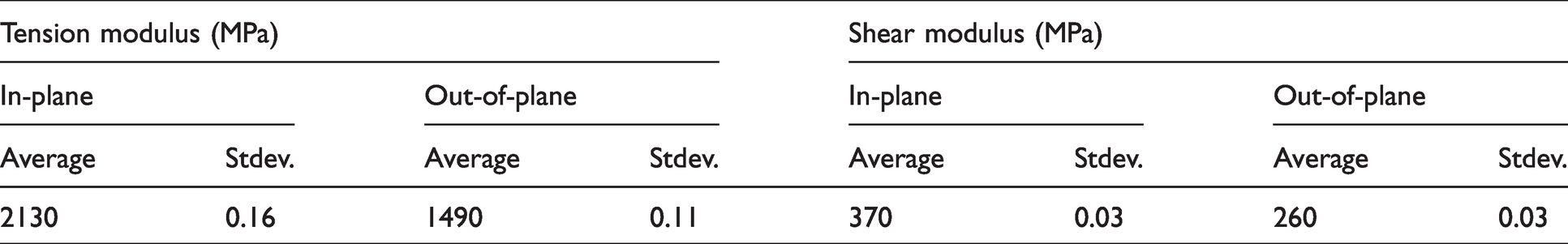
To characterize the material for design purposes, out-of-plane build tension tests were run at a rate of 1 mm/min. Force and strain information were recorded at a rate of 0.5 Hz using Instron test software. The test specimens were rectangular in cross-section and approximately 10.14 (±0.03) mm and 3.13 (± 0.02) mm in width and thickness, respectively. In-plane build tension data was taken from Phillips et al. 50 Shear tests were conducted according to ASTM D5379 at a rate of 2 mm/min acquiring force and strain information at a rate of 2 Hz, where specimens were approximately 11.77 (±0.13) mm and 2.66 (±0.12) mm in test-section width and thickness, respectively. Results (Table 2) show that the in-plane material response in tension and shear was approximately 49% and 42% higher, respectively, than the out-of-plane response. In general to maximize the material stiffness, the primary loading should be oriented in-plane, but the out-of-plane material properties were deemed sufficient while providing higher resolution and less friction for the telescoping sections.
AM tension and shear modulus test results for Onyx material.
Two skin materials were evaluated for use on the models: 3M VHB 4910 (Cambered and 0012 A models) and Latex rubber (0012B model). In terms of manufacturing suitability, the VHB 4910 had an acrylic adhesive on both sides making it easy to apply as a skin, but it is only available with a thickness of 1.018 mm and density of 960 kg/m3. The Latex did not have a backing but was commercially available at thicknesses as low as 0.15 mm but at a slightly higher density of 998 kg/m3. The Latex was therefore lighter as a skin but more difficult to attach to the nylon telescoping structure.
Interior geometries
Interior geometries were built around telescoping members as the primary carrier of bending load from aerodynamic forces. The several geometries chosen were meant to be efficient in terms of bending stiffness per gram, but no attempt was made to computationally optimize the telescoping members in this work. The interior arrangements for the models (Figure 3) were such that each telescoping segment inserts into a collar on the next rib with a sliding gap of 0.2 mm, except for 0012B which had a 0.12-mm sliding gap. The wall thickness on all hollow members was kept constant to a dimension of 1.5 mm.

Telescoping spar interior schematic for all models.
For each consecutive rib, telescoping rods were adjusted backward or forward to accommodate the telescoping members from the previous rib. This means that the structural center of mass moves forward and backward as a function of span. For each model, the rib spacing was a minimum of 40 mm with a shortened collar (14.6 mm) on one rib to allow for a compression spring with a minimum length of 25.4 mm (Figure 3). The compression spring was sized according to the measured stress–strain behavior of the VHB skin material to provide enough extending force to extend the wings at least 100%. A tether was placed from the root to the wing tip in order to contract the span to the minimum value. When the wing models were in the compressed state, the springs were almost fully compressed and exerted approximately 30 N of extension force. When the tether was released, the compression spring pushed against the adjoining ribs stretching the skin to a theoretical maximum of 87.0 mm for each section (∼115% extension) where the spring equilibrates at approximately 10 N of extending force. For each eight-segment model that equated to a theoretical minimum span of 360 mm (eight segments of 40 mm and the 5 mm thick ribs) and a maximum span of 736 mm (eight segments at 87 mm plus the ribs).
Experimental methods
To evaluate the aerodynamic and structural performance of each model, wind tunnel testing at real-world flight speeds was conducted. Test models were cantilevered in a 3 ft × 3 ft × 6 ft recirculating wind tunnel and mounted to a servo-motor to control wing angle of attack (α). An ATI Nano 25 six-axis force balance was mounted between the wing and the servo motor to measure aerodynamic forces, see Figure 4. Lift and drag force data was acquired at 1 kHz over 5 s for each α using a National Instruments DAQ system. Individual channel noise was on the order of ±0.001 N at rest which, due to mixing of channels associated with the six-axis balance, translates to a lift and drag calculation noise on the order of ±0.02 N. Note that the effects of span morphing are in altering the total lift on the aircraft, and as coefficient of lift scales with wing area, CL is not always an accurate representation of the effects of span morphing. However, to maintain consistency with other aerodynamic studies, CL is used to compare the performance of the wings. It should be noted that CL is calculated by the reference area of the wing in each configuration (short, medium, long), thus revealing the changes in lift resulting from other sources like AR, wing twist, or unintended wing camber. A simple error analysis, given the speeds associated with the testing, shows that magnitude of uncertainty associated with CL and CD was below the size of the markers used in later plots. Experiments were conducted at 2.25, 4.5, and 8.9 m/s, which correspond to Reynolds numbers of 18,000, 36,000, and 71,000, respectively. Wing α was controlled with a Galil DMC 4020 servo controller with an attached 4000 count/rev encoder. Uncertainty in the α due to the controller was approximately ±0.1°. Wings were typically tested from α = –12° – 12° in 1° increments, but sometimes, test was cut short when stall was clearly observed.

Wind tunnel testing instrumentation schematic. Model is cantilevered outside of the wind tunnel test section with DIC mounted above.
For mounting purposes, a non-extending 50 mm section was attached near the root of the wing. Three different span conditions were tested: a short (432 mm, fully contracted), medium (600 mm), and long (762 mm, fully extended). Wind tunnel blockage was kept below 2.5%, which is below the recommended 5% maximum blockage. Also, while the longest wing was around 80% of the span of the tunnel, for this proof of concept testing, wing-tip vortex-wall interactions were neglected.
In-situ three-dimensional digital image correlation (DIC) was used to measure the in-plane and out-of-plane displacements as well as the initial positions of the three wing models within the wind tunnel. Point Grey Research digital cameras with a native 5 MP resolution were positioned above the tunnel approximately 700 mm from the wing at a tilt angle of 30°. Cameras were focused on the mid-chord and mid-span for all testing. Images were recorded at 10 Hz for 5 s (50 total images), and image pairs were correlated using VIC3D to create displacement field data at a subset and step size of 27 px and 5 px, respectively. DIC calibration utilized the VIC3D calibration plates and corresponding calibration system, leading to a resolution error on the order of microns.
Results
Forces
The Cambered wing model was the first designed and tested in the wind tunnel. Lift and drag results for the fully compressed case are shown in Figure 5. In general, the results shown in Figure 5 are expected at these low airspeeds, with linearity of CL increasing significantly with Reynolds number. At the lowest Reynolds number, the lift and drag coefficients were the least steady. While the standard error of the measurements was low, the uncertainty of the lowest Reynolds number case was obviously larger. This was caused primarily by the notably small forces generated at this Reynolds number. Performance analysis in this study will focus on the higher Reynolds number cases due to this uncertainty in the results. Stall was observed at around 11° for all the Reynolds numbers tested on the Cambered wing. While the lift was low for lower airspeeds, it was of the same order of magnitude as the weight of the wing model at 8.9 m/s (Re = 71,000), a typical flight speed for a vehicle of this size.

Cambered model lift and drag calculations for 432 mm span.
When the wings were extended to the medium or long configurations, they expectedly produced more lift than when in the short configuration. However, the internal structure and interaction of wing skin tension, telescoping rod friction, and extension tether location resulted in poor shape control as the wings were extended. The resulting wing twist generated an incidence change in the wings of several degrees and caused the lift coefficient to increase more significantly than expected. For example, the Cambered wing in short configuration had a slightly positive CL value at 0° α, but when extended the lift coefficient exceeded CL = 0.6 (Figure 6, top row). Somewhat surprisingly, the stall angle remained around an α of 10° for the medium extension but dropped below 7° in the long configuration. There was also a notable diminishing return on additional lift generated as span was increased on the Cambered and 0012A models. This was likely because the wings twisted to their maximum extent by medium extension and further extension resulted in little additional performance increases. By the third iteration of the spanwise extending wing, the 0012B model, much of those detrimental features were mitigated. However, a failure of the latex skin (as opposed to VHB skin on the other models) made testing at the highest Reynolds number impossible. Further analysis and discussion of these unexpected shape behaviors will be shown in the sections detailing the DIC results, and analysis of AR effect will also be shown separately.

Lift versus angle of attack for 8.9 m/s (Re = 71,000) testing, increases in span are marked dark to light. Short span aerodynamic behavior is similar across all models.
Digital image correlation
To further quantify the twisting and sweeping behaviors that were qualitatively observed during force testing, a DIC system was used to record displacement data on the wing models. DIC results showed relatively small sweep and twist angles when the 0012A model was in the short configuration (Figure 7). When extended, the model was more compliant and experienced significant sweep viewed from above in Figure 7. This sweep was caused mainly by a misalignment between the structural center of mass and the placement of the spring and tether. Similar behaviors were observed for the Cambered wing. It was noted that the sweep could be lessened by intelligently placing the tether and spring more rearward, which was done on later models (0012B). Each model in this research was treated in its most simple state without attempting to eliminate sweep, thereby enabling assessment of poor shape control as a factor effecting span changing small UAVs. When freely cantilevered in the wind tunnel, the vertical wing-tip displacements associated with gravity at 0 m/s were on the order of –50 mm, –100 mm, and –200 mm for short, medium, and long configurations, respectively (Figure 7). This increased drooping of the wing was expected during extension as model stiffness decreased when extended.

0012 A model DIC data at 0 m/s and 0°α (inflow from figure top). Prominent sweep and vertical tip drooping can be observed (negative z position away from the camera) as model is extended.
Chord-wise surface cross-sections were extracted for Cambered wing model at the wing root, second, fourth, sixth, and eighth rib from the DIC information and are presented in Figure 8. When no aerodynamic loads were applied, the wing was observed to droop approximately 65 mm in the short configuration or around 15% of the span. In the short configuration, the twist and sweep angles were near zero and were nominally constant as a function of spanwise position, both when the wing model was experiencing aerodynamic loading and when free hanging. However, when in the extended configurations, and especially for the highest speed and α recorded (Figure 8), twist and sweep angles increased significantly as a function of spanwise position. In this particular case, the wing loading caused twist angles resulting in wing tip α in excess of 30°, well past the static stall angle. When compared with the lift results presented in Figure 6, it appears that the twisting of the outboard sections led to the early stall onset.

Cambered model DIC chord-wise slices for free hanging and selected α at short, medium, and long configurations (Re = 71,000).
Similar data was recorded for the 0012A and 0012B wing models and are shown in Figures 9 and 10, respectively. For the 0012A, it was noted that the wing experienced some sweep in the short configuration, which was caused by the placement of the tether in relation to the structural center of mass. Unlike the Cambered wing, the wing tip of the 0012A-short model did not lift significantly and align with the root displacement as the weight of the 0012A model was greater. Further, when the wing was extended to medium and long configurations, the droop and sweep of the wing tip became significant, as observed in Figure 7. Lessons learned from the development of the 0012A model were implemented on the 0012B model which had significantly less twist and sweep for the cases that could be tested. Note that the failure of the wing skin, which was changed from 0012A to 0012B models, limited the data in Figure 10. Despite the skin failure, the twist and sweep that negatively impacted the Cambered and 0012A models were generally eliminated on the 0012B model.

NACA0012A model DIC chord-wise slices for free hanging and selected α at short, medium, and long configurations (Re = 71,000).

NACA0112B model DIC chord-wise slices for free hanging and selected α at short, medium, and long configurations (Re = 71,000).
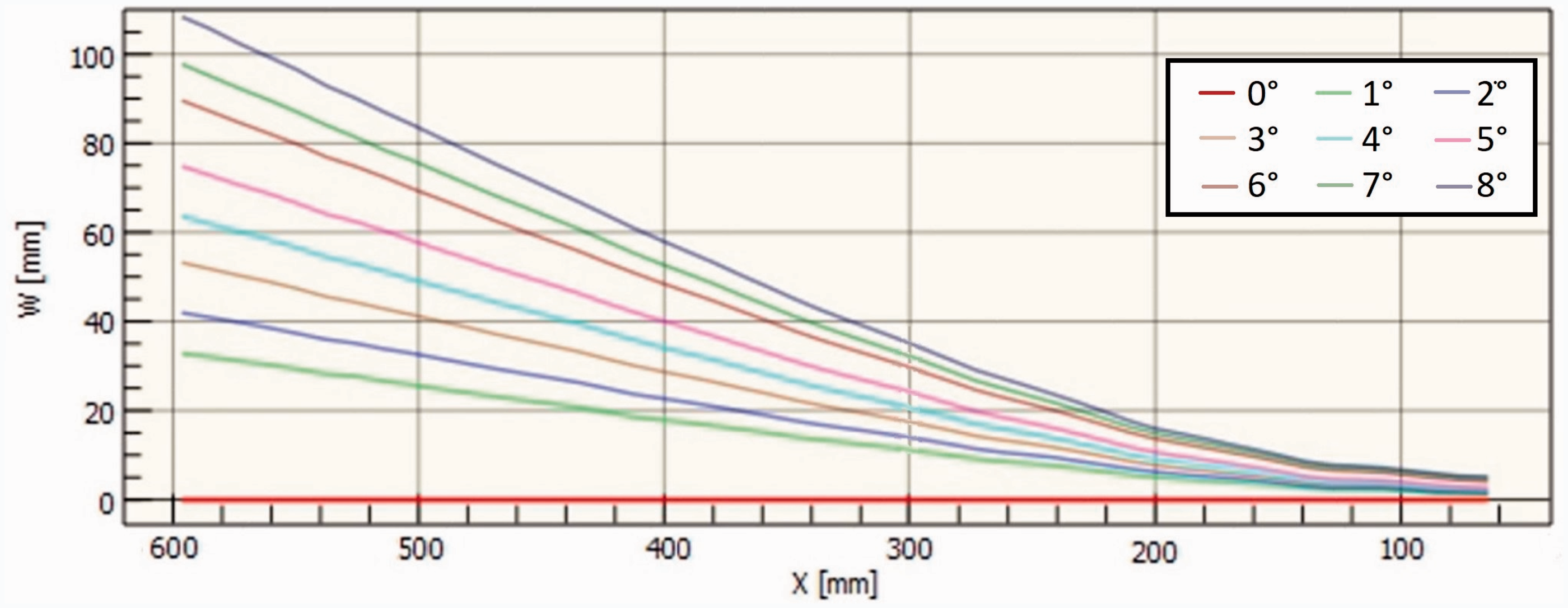
The use of a stretching skin as opposed to overlapping rigid skin (as was used in previous studies) also lead to a need to consider the potential deformation of the skin as the span is extended. Specifically, due to the Poisson’s ratio, the skin might be expected to bow in for section of skin between ribs. Furthermore, due to the pressure and suction of the airflow, additional deformation of the skin might be expected. In order to determine if the wing does exhibit any bowing, the displacement of the 0012B model along the quarter chord in the medium configuration at Re = 71,000 is shown in Figure 11. Note that, in accordance with Figure 7, the wind tunnel wall is located on the right side of the wing, and thus, in Figure 11, the right-hand side of the wing is constrained, thereby leading to minimal displacement. Overall, this data indicates that, for the cases studied, the overall bowing is minimal.
Span normalized tip displacments as a function of (top) Reynold’s number at medium span and (bottom) span at Re = 71,000.
For a more quantitative comparison of the structural performance of the models, the wing-tip position was extracted at the wing-tip quarter chord position and is plotted in Figure 12 as a function of

Span normalized tip displacments at Re = 71,000.
The short span across all models showed a general wing-tip travel of –60 to 10 mm for Re = 18,000–71,000 which amounts to –14% to 2% of the span as seen in Figure 12. The model with the greatest stiffness, 0012B, had a minimum wing-tip position of –24 mm and a maximum of 10 mm. Each model in the short span configuration had little sweep, and qualitatively, the wing-tip displacement was rather small. The increased compliance of the model at medium span led to a larger wing-tip travel most exaggerated for the Cambered model which did not stall until 10°
Influence of build orientation
A direct comparison of build orientation on the structural response is hindered by the multiple changes in wing design between each iteration. Qualitatively, printing the sections out-of-plane was easier in terms of manufacturing, allowing the use of more complex shapes to increase bending stiffness. For example, using telescoping squares sections instead of circular rods increased the second area moment of inertia 3× for models 0012A and B compared to Cambered for some increase in mass. The design trade in printing out-of-plane (decreased material stiffness) is however seen in Figure 12, where the NACA 0012A model experienced relatively large negative wing-tip displacements due to gravity which were not overcome by generated lift. The use of a lighter skin and square spar cross-section for model NACA 0012B overcame this issue. It should also be noted here that the friction associated with the build direction caused the Cambered wing model to not extend as freely or quickly at the out-of-plane build models. The sliding friction increases the necessary actuation forces which generally would increase the energy required for span change in a real vehicle.
Influence of camber
To evaluate the effects of camber on performance, the aerodynamic data of the three wing models was compared. Results shown in Figure 13 are all for Re = 71,000 at the medium span condition. Trends were the same across various speeds; however, the measurement uncertainty was lowest at higher velocities. The Cambered wing model generally outperformed the symmetric airfoil models by stalling at a higher

All models aerodynamic data at Re = 71,000 medium span.
Influence of AR
The primary goal of a span-changing aircraft is the increase in lift with a presumed constant airfoil shape and chord. Realistically, the airfoil shape between ribs, when considering a soft skin, was expected to be scalloped as the Poisson’s ratio causes the skin to contract in chord and thickness as it expands in span unless reinforced. While this effect might negatively impact aerodynamic performance, the increase in AR would be expected to offset some of the losses. The Cambered wing in short configuration (AR = 3.6) performed as a nominally symmetric airfoil would (similar to 0012A or 0012B) due to wing-tip twist and sweep (see Figure 8) lowering the measured CL (Figure 6). When the wing was extended to the medium configuration (AR = 5), the lift performance at low angles increased significantly in accordance with positive wing-tip twist with little change upon increasing to AR = 6.4. AR significantly impacted L/D ratio, due to the large changes in lift and small changes in drag, with a L/Dmax of 9.4, 14.8 (57% higher), and 18.5 (97% higher) for AR 3.6, 5.0, and 6.4, respectively.
For the 0012B wing model, the effects of twist and sweep were more limited compared with the Cambered or 0012A model. These results are reflected in the lift and drag data which are more similar for AR = 3.6 and 5.0 compared to the other models. When in a short configuration, the lift slope was linear and stalled near 10°, which was expected at this Reynolds number. Extending the wing to AR = 5.0 resulted in 0.12 nominal increase to the lift curve, while slightly reducing the drag. AR increase from 3.6 to 5.0 resulted in an increase in aerodynamic performance (L/Dmax) from 9 to 13.5 (50% higher). These results clearly indicate that increasing the span at the scale and weight of a small UAV is feasible and highly beneficial in terms of range and endurance of the aircraft.
Conclusions
A review of design methodology and wind tunnel test data was presented for evaluation of the suitability of AM span-changing wings for use in small, fixed-wing UAVs. Despite the lower strength and stiffness of AM polymer compared to traditional aerospace materials, aerodynamic test data indicated that the wing models were all capable of generating lift exceeding their own weight. In terms of potential dollar cost, it has been shown that there is an opportunity for rapid, low-cost, spanwise changing UAV development.
The aerodynamic performance, as measured by L/Dmax, was shown to increase with increased wing span for all the models. On more flexible models, the aerodynamic performance was increased by 57% (Cambered model-medium) and 97% (Cambered model-long), but much of those performance gains were from significant, unplanned structural deformations. On a more traditional model where the wing displaced smaller amounts with limited twist, a 50% increase in L/Dmax was observed (0012B model-medium). While there is generally preference for predictable spanwise changes with limited twist or sweep, it should be noted that optimal increases in performance could be obtained by including those types of deformations.
The data contained herein provides a basis for fluid-structure interaction validation of deformable bodies where lighter weight, less stiff solution is more likely to present wing twist and sweep. The degree to which certain amounts of deformation such as twist are acceptable are a balance of complexity and energy cost at the expense of stiffness and weight. A low energy actuation solution based on this study may be a spring/tether pair with an embedded servo in the fuselage which should have high actuation speed potential when a rather linear-elastic skin like Latex is used.
In flight application, shape change provides the ability to adapt to different mission spaces by shortening span in flight for agility low to the ground and lengthening span at takeoff, landing, and during loiter for increased endurance. Through intelligent application of variable wing span by considering the mass, aerodynamic performance, and control, a vehicle would be able to optimize its performance for complex missions by adapting span regularly in response to varying phases of flight.
Footnotes
Acknowledgements
The work presented in this manuscript built upon internal efforts started in part by Mr Chris Kroninger and Mr Aaron Harrington and they are thanked for their technical advice. Experimental testing of the Markforged Onyx material was conducted by Mr Michael Coatney for which his effort is acknowledged.
Declaration of conflicting interests
The author(s) declared the following potential conflicts of interest with respect to the research, authorship, and/or publication of this article: The views and conclusions in this document are those of the authors and should not be interpreted as representing the official policies, either expressed or implied, of the Army Research Laboratory or the US Government. The US Government is authorized to reproduce and distribute reprints for Government purposes notwithstanding any copyright notation herein.
Funding
The author(s) disclosed receipt of the following financial support for the research, authorship, and/or publication of this article: The research was funded by the Army Research Laboratory.