
Abstract
Increasing endurance is a major challenge for battery-powered aerial vehicles. A method is presented which makes use of an updraft around obstacles to decrease the power consumption of a fixed-wing unmanned aerial vehicle. A soaring flight controller has been developed that can autonomously soar while the unmanned aerial vehicle keeps its relative position to that of a moving object. Multiple simulations have been performed to analyse the limitations of the soaring controller under different conditions. The effect of a change in wind velocity and updraft has been analysed. The simulations showed that an increase in updraft decreases the energy consumption of the flight controller. An increase in wind velocity results in a higher updraft requirement, while a decrease in the wind velocity requires less updraft. The simulations achieved sustained flight at 0% throttle. The controller has been validated experimentally using the updraft generated by a moving ship. The practical, autonomous tests reduced the average throttle down to 4.5% in front of a ship. The method presented in this study achieved successful hovering flight using an energy control module for longitudinal positioning.
Introduction
While the usage of autonomously flying vehicles is increasing, and people are getting more confident with new technologies, a shift towards sustainable energy is also noticeable. It will not be possible in the future to design everything on fossil fuels, and either regulations or restrictions are appearing, which hinder the development of wasteful energies or support the use of sustainable products. Even though it is possible nowadays to fly up to 15,000 km on a commercial aircraft, this cannot be achieved using electrical energy. The main reason for this is the lower energy density of batteries compared to fossil fuels.
The same reasoning applies to the usage of unmanned aerial vehicles (UAVs). Current projects mainly lack the endurance and range to become successful. While drones can increase efficiency in numerous processes, they still lack battery power to replace the prevailing technology. Although battery efficiency is continuously improving, engineers are required to come up with alternative technologies to overcome this barrier. One of these is soaring: a technique that extracts energy from the wind. Previous research has shown that only wind energy can deliver the entire world electricity. Miller et al. 17 provided an estimate of 18–68 TW that can be extracted using onshore energy. Jacobson and Archer 13 showed that even 80 TW would be possible in case one included offshore energy extraction. Physical limits and losses reduce these numbers to a lower estimate. Nevertheless, the demand for wind energy is increasing, and new technologies can increase efficiency significantly.
Soaring had already been discovered in 1883. Inspired by Albatrosses, Lord Rayleigh discovered the first soaring technique. In his research, he proposed the dynamic soaring manoeuvre. 21 Subsequently, it was found that many other birds were able to fly nearly indefinitely without flapping their wings. Examples include Albatrosses,22,23,24 Andean Condors, 25 Frigatebirds 26 and many more. Allen 1 has shown in his simulations that soaring can increase the endurance of UAVs in the summer from 2 to 14 h. This finding could increase the use-cases for drones significantly.
Soaring has since been split up into two categories, static soaring and dynamic soaring. Static soaring makes use of a constant upward wind to gain energy. The wind can either come from thermals or any obstacle generating a vertical component of wind (orographic lift). Dynamic soaring makes use of a wind gradient to increase the relative air velocity between cycles.
Past research on dynamic soaring focuses on finding the optimal flight path and the possibilities of flying in crosswind directions.3,8,10,23,24 The main contributors for static soaring are researching whether UAVs can use thermals to glide indefinitely1,5,29 or whether static soaring techniques can be used in urban environments.6,7,16,18,19,27,28 For both of these techniques, the drone either needs to move from one updraft to the next one, or it has to constantly hover above the same location to remain airborne. There exists a strong coupling between the location of the updraft itself and the flight trajectory of the UAV.
While previous research is only focused on harvesting wind from static objects, this paper aims to analyse whether autonomous flight without the usage of throttle is also possible in the wind field generated by a moving obstacle. Using a moving obstacle allows following a predefined flight path and makes it possible to adapt the relative wind based on the current environmental conditions. The critical wind conditions under which indefinite soaring is possible and the limitations of the flight controller will be investigated. Piloted flights at stronger winds, conducted before the start of this research, have shown already that flying without throttle is indeed possible. This paper contributes to the development of a novel control method for autonomous and throttle-less soaring in front of a moving obstacle. By performing both simulations and practical tests, this paper aims to investigate whether indefinite, autonomous soaring in front of a moving obstacle is possible and how to presented flight controller reacts under different wind conditions.
First, both the simulation and experimental setup that is available for testing are introduced. After that, the flight controller is presented, and then the results and discussion of the simulations are given. The last section gives the experimental results and their interpretation.
Method
This section of the report provides an overview of the research environment itself. The first subsection summarises the theory behind orographic lift and explains how it can be achieved using simple formulas. Then, both the simulation setup, as well as the experimental setup are explained. Subsequently, the actual flight controller is illustrated.
Theory
Literature from Lee et al.,
15
as well as from Patel,
20
shows that the effect of the updraft can be modelled into the differential equations of motion by adding the relative motion between the air and the ground. Assuming that the UAV rotational rates are small and that control surface deflections do not affect forces, the relative motion of the UAV with respect to the ground is given by equation (1)

In order for the aircraft to fly indefinitely, the vertical wind speed has to be at least as high as the minimum rate of climb. This condition is stated by equation (2)


Sketch of the experimental setup. The desired soaring position is located in front of the ship where the uplift occurs, which is decided by wind speed and the ship’s ground speed.
Simulation setup
The general SIM environment of the Paparazzi UAV software will be used as the primary simulation environment.4,9,11 This is an essential fixed-wing simulator without inertial measurement unit simulation or any sensor models.
The Paparazzi environment comes with a ground Global Positioning System (GPS) module sending the ground station position to the UAV. The movement of the ship is simulated by changing the lateral and longitudinal position of the ground GPS module in the simulation. This position can be increased in both directions by a predefined value at each time step.
The last component that needs to be simulated in the testing environment is the wind flow generated around the ship. Paparazzi comes with the built-in Gaia module, which makes it possible to set speed, direction, and updraft of the wind for the whole simulation environment. This means both updraft and horizontal wind speed have are decoupled from each other in the simulation. In practice, however, both the updraft and the horizontal wind speed are far from being uniform around a hill-shaped object. 12 The more complex shape of a ship increases the turbulence even more.
To test the flight controller, a couple of experiments are performed that investigate the power consumption over a range of different wind regimes. The parameters are given by a change in wind speed and updraft.
Experimental setup
To test the algorithm and analyse the throttle performance of the flight controller in real flight, it is decided to use the fixed-wing model of Parrot, namely the Disco. Table 1 shows the basic properties of Disco aircraft. The Parrot Disco is stable enough for flying inside these heavy wind conditions. The onboard pitot tube of the Parrot Disco also makes it possible to use airspeed related control loops instead of relying on GPS ground path tracking. A couple of modifications have been made to improve the overall performance. First, the general Parrot autopilot has been overwritten with the Paparazzi UAV software to enhance the autopilot capabilities. Next, to obtain better GPS accuracy, the onboard GPS has been replaced with a u-blox M8P GPS module. This makes it possible to correct for satellite propagation errors using Real-Time Kinematic (RTK) positioning, and as such, provide up to centimetre-level accuracy.
Properties of the Parrot Disco UAV.

For the research, testing of the flight controller was performed on an emergency towing vessel that has been made available by the Dutch coast guard. Measurements of the ship are shown in Table 2. Several piloted flights in front of the ship have shown that its size and speed are sufficient to achieve throttle-less soaring. The maximum speed of the ship is equal to 8.2 m/s, and with its width of 65 m and height of 8 m, it can generate enough updraft.
Properties of the guardian ship (the emergency towing vessel used for the flight test).

The ground segment consists of a laptop running the Paparazzi UAV software. It is connected to the drone using Wi-Fi. An M8P GPS module is used to send satellite propagation errors and the current position of the ship to the drone. A general impression of the main experimental setup can be seen in Figure 2.

A general impression of the main test setup.
Flight controller
The central part of the current research is focused on changing the outer loop of the Paparazzi UAV flight controller. This loop is responsible for the navigational routine. The main purpose of the flight controller is to set flight attitude and speed in order to allow flight without throttle. Both of these desired parameters are then sent to the inner loop to obtain the required elevon deflections and throttle.
In the vertical plane, a controller based on balancing kinetic and potential energy, as described by Lambregts14, was used as the basis for this work. The implementation found in the Paparazzi-UAV project 4 has been used as a starting point.
While the total energy is regulated by the updraft, the controller is used to balance the kinetic and potential energy. Staying at a constant energy balance makes the aircraft stay on a diagonal climbing line with respect to the ship. This diagonal line is depicted in Figure 4.

Diagonal climbing line in which the flight controller finds a stable situation. From point A the drone will start pitching up to trade kinetic with potential energy. The drone will move to point B, at which it will start to increase its kinetic energy to match the ground speed of the ship. The decrease in potential energy will result in it moving into a region of higher updraft until it remains airborne. From point C, potential energy is traded with kinetic energy to reach region D. Here, the increased updraft will result in the UAV finding an equilibrium position somewhere above point D.
By balancing both potential and kinetic energy and due to the shape of the updraft, the UAV is automatically finding an equilibrium position at a diagonal climbing line through the region of the maximum updraft. This is due to the fact that whenever the UAV is located in front of this line (point A of Figure 4), it will start pitching up to decrease the kinetic energy and increase the potential energy resulting in a flight path towards point B. Here the pitch angle is reduced until the ground speed of the drone equals the ground speed of the ship. This results in the UAV flying into a region of higher updraft at which both potential and kinetic energy are in equilibrium.
Whenever the UAV is located behind the diagonal climbing line (point C of Figure 4) the pitch angle is reduced to convert potential energy to kinetic energy. It will move to point D and enter a region of higher updraft. The drone will then increase the pitch angle to maintain the same ground speed as the ship. It will keep climbing until it reaches an equilibrium position.
With an ideal wind field, the flight controller should decide to use no energy at all and leave the power consumption of the motor at 0%. Due to safety reasons, however, it was decided to allow throttle usage in case the UAV is located too close to the ship, or if the UAV is not able to reach its climb setpoint using the pitch controller exclusively. To define these safety regions, a waypoint is set at a specified distance to the ship. As soon as the UAV passes this waypoint in the longitudinal direction, the proportional gain of the airspeed controller starts the throttle. This waypoint is also used to calculate the positional errors of the flight controller.
A block diagram of the longitudinal controller is depicted in Figure 3. As seen, there are two main loops controlling both potential and kinetic energy. The longitudinal x-axis position is first fed into a proportional and integral controller in order to obtain an airspeed setpoint. The kinetic energy error is then fed into both an integral and a proportional controller. The proportional term makes sure that the motor is started if the UAV is located too far behind the waypoint. This also ensures that the UAV will not crash into the ship during sudden wind gusts propelling it backwards. In case the wind is too strong, the integral term of the flight controller guarantees that a minimum amount of throttle is constantly used to overcome drag forces if required.
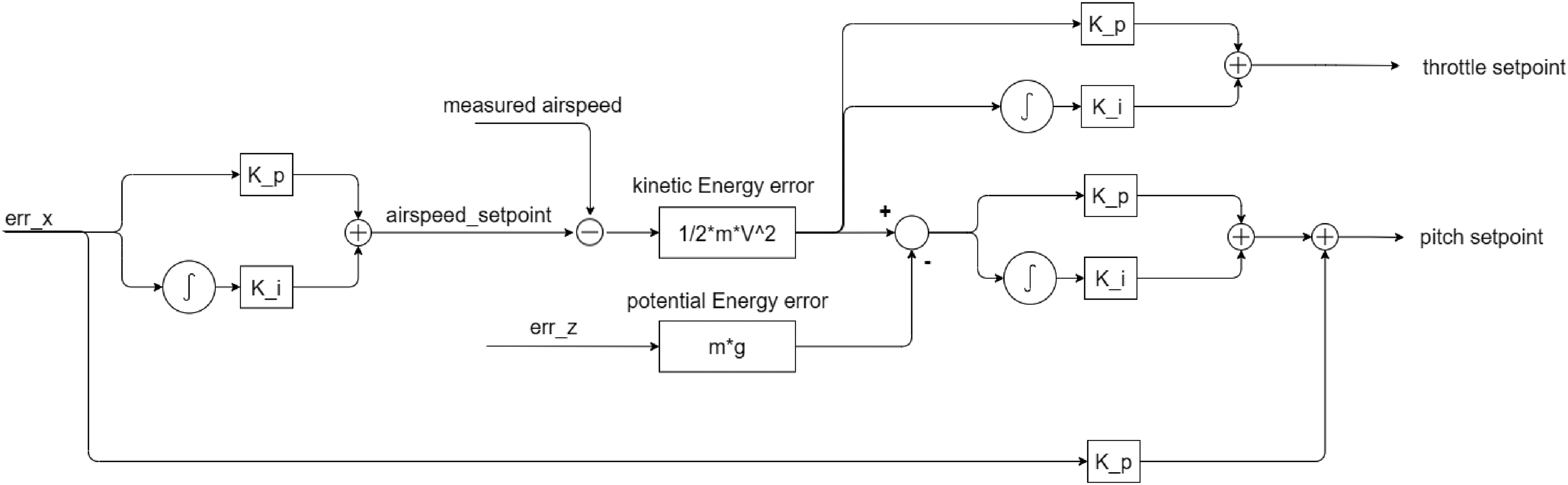
Block diagram of the longitudinal flight controller. The controller balances kinetic and potential energy that is obtained at the given wind conditions. In case too much energy is available, a pitch up movement bring the UAV into a region of lower updraft and hence less energy. A pitch down movement on the other hand is used to trade potential energy with kinetic energy to move into a region of higher updraft. A proportional term on the throttle controller ensures the usage of throttle in case balancing is not possible.
The kinetic energy is also fed to the potential energy loop to calculate the distribution energy error. This is the amount of kinetic energy that needs to be converted to potential energy. After that, it is converted to a pitch angle using both a proportional and an integral term. On top of that, a pitching term dependent on the longitudinal x-axis position is added. A pitch up movement is commanded to increase the horizontal drag of the UAV and move backwards. A pitch down movement is for decreasing drag and thus moving forward. This part of the controller is used as a feedforward system so that the controller first tries to nullify its positional error using pitching behaviour. In case this is not possible, the airspeed loop will ensure that the UAV is not going to crash into the ship or sea.
Even though both the pitch and the throttle loop are used to nullify the x-axis error, they are used for different purposes. The pitch loop is responsible for trading excess potential energy into kinetic energy. The throttle loop, on the other hand, is only needed in case the pitch loop is not able to set both climb and speed-related requirements simultaneously. These limitations will be explained in the upcoming sections.
Figure 5 clearly shows the gradient of vertical wind speed in the wind field. The wind field has been generated by two-dimensional computational fluid dynamics (CFD) simulation with a ship model of similar size. With an inlet speed of 4 m/s, similar conditions as in the experimental test flights have been created. A small region of maximum updraft is found somewhere in front of the ship. Closer to the ship, the updraft is decreasing due to an increase in ground friction. This decrease in ground friction happens quite drastically and hence the design of the flight controller should take into account that this region should never be reached. Further away from the ship, the vertical wind velocity slowly converges to the undisturbed flow. Both the shape and gradient of this updraft ensure that the presented energy controller is automatically able to find an equilibrium position on the left-hand edge of the maximum updraft. This is due to the fact that whenever the aircraft is located too far away from the obstacle, it is commanding a pitch up movement resulting in an increase in Drag and Lift. This results in the UAV flying into a region of the higher updraft. As a consequence, the controller is now decreasing its pitch angle due to the increase in potential energy and converges to the left-hand side of the location of the maximum updraft. The same applies to a situation in which the controller is located too close to the obstacle. Here a pitch down movement ensures that it flies into the region of the higher updraft. Due to this increased updraft, the controller will further increase its pitching down behaviour to trade the just gained potential energy with kinetic energy. As a result, the UAV is flying further away from the ship, ensuring the same convergence.
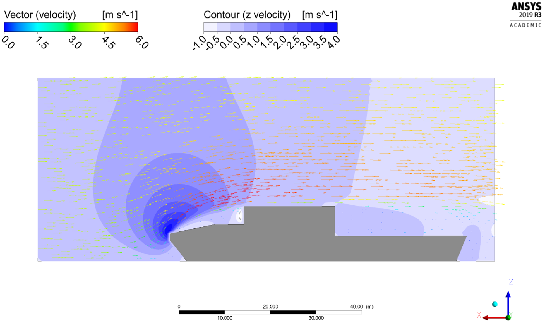
Two-dimensional CFD simulation of the wind field around a ship. ANSYS Fluent 19.5.0 version 2 was used for the simulation. Inlet wind speed was set to 4 m/s. The shape of the ship was simplified for calculation efficiency.
Last, a separate roll loop using a simple PID controller has been added for lateral positioning. Using the y-axis positional error, this controller is only activated in case the UAV is more than 2 m away from its target. In case we are already flying in the desired position, the heading is simply set equal to the heading based on the GPS positions received by the ground station. This discrete switching of the controller is used in order to ensure that the UAV is constantly flying at the set position. The internal Paparazzi roll loop can cope with the lateral positional requirements using heading based navigation while the errors are small. As soon as the y-positional errors become too large, the roll controller switches to a stronger PID controller, ensuring faster movement towards the required position. The final roll loop is represented in Figure 6.

Block diagram of the roll controller. Discrete switching of the controller depending on the y-axis error ensures convergence of the flight controller in the wind field.
Simulation
In this section, the results of the different simulations are given. Then, a follow-up discussion will interpret and explain the results.
Simulation results
The first performed experiments monitor the throttle usage of the UAV for a changing wind speed and updraft. For this, the above-mentioned flight controller has been subjected to a range of different wind speeds and updrafts. The position in front of the ship had to be kept for around 60 s at each wind condition. The speed of the ship is simulated with an average speed of around 4 m/s.
Simulations have shown that the actual flight boundaries are limited between two cases. The upper case is reached at the maximum throttle, while the lower case is reached at the minimum throttle.
The minimum throttle condition is illustrated in Figure 7. As can be seen, the energy controller is able to hover at the given wind conditions using 0% of throttle. Thus this limitation is more prevalent during autonomous soaring. Decreasing the relative horizontal wind speed or increasing the updraft further, results in the flight controller decreasing the throttle further to compensate for the additional gain in total energy. As the minimum throttle condition has been reached already, this results in the flight controller losing track of the waypoint and flying away from the ship. Additionally, it can be noticed that the altitude error is decreasing (and hence the altitude increasing) significantly during this manoeuvre.

The lower case at the minimum throttle. The decrease of wind speed in the simulation ensures that the UAV is reaching a maximum energy condition. The throttle can not be decreased any further and the UAV is losing track of the wind field due to its stall speed requirement. A decrease in z-axis error and hence an increase in height is also observed.
The maximum throttle condition is presented in Figure 8. Here the energy controller has reached the maximum throttle and is not able to increase the throttle any further. Increasing either the horizontal wind speed or decreasing the updraft will result in the UAV colliding against the ship. Before the collision, a decrease in altitude can be observed. While Figure 8 illustrates a case where 100% of throttle was achieved, it should be noted that this lower case can also exist at the lower throttle. This phenomenon happens whenever the throttle controller can not compensate for the pitch errors created at the given wind conditions anymore.

The upper case at maximum throttle. The UAV is reaching its maximum throttle condition when the wind speed is increased in the simulation. As the throttle can not be increased any further the UAV is either crashing into the boat. An increase in z-axis error and thus a decrease in height is also observed.
Using the knowledge of the above-mentioned boundaries, it is possible to assign a feasible flying regime to the current flight controller under alternative wind conditions. The wind regime is given by all the wind conditions in which the flight controller is able to hover within a 5-metre accuracy in front of the ship with full access to the throttle. To generate the wind regime, simulations have been performed in which the UAV had to hover for at least 5 min in front of the moving ship with a positional accuracy of at least 5 m. The required throttle during these 5 min has then been averaged to obtain an estimated energy requirement. The final wind regime results are depicted in Figure 9. The figure has been generated by simulating the ship's movement at 4 m/s in an arbitrary direction. Both horizontal wind speed and updraft are then generated in the simulation, and the throttle consumption of the UAV to hover in front of the ship has been monitored. The average throttle consumption over a range of 5 min is then depicted in the figure for each combination of wind speed and updraft. The main limitation of this simulation comes from the fact that updraft and wind speed are decoupled and changed separately. They do not affect each other.
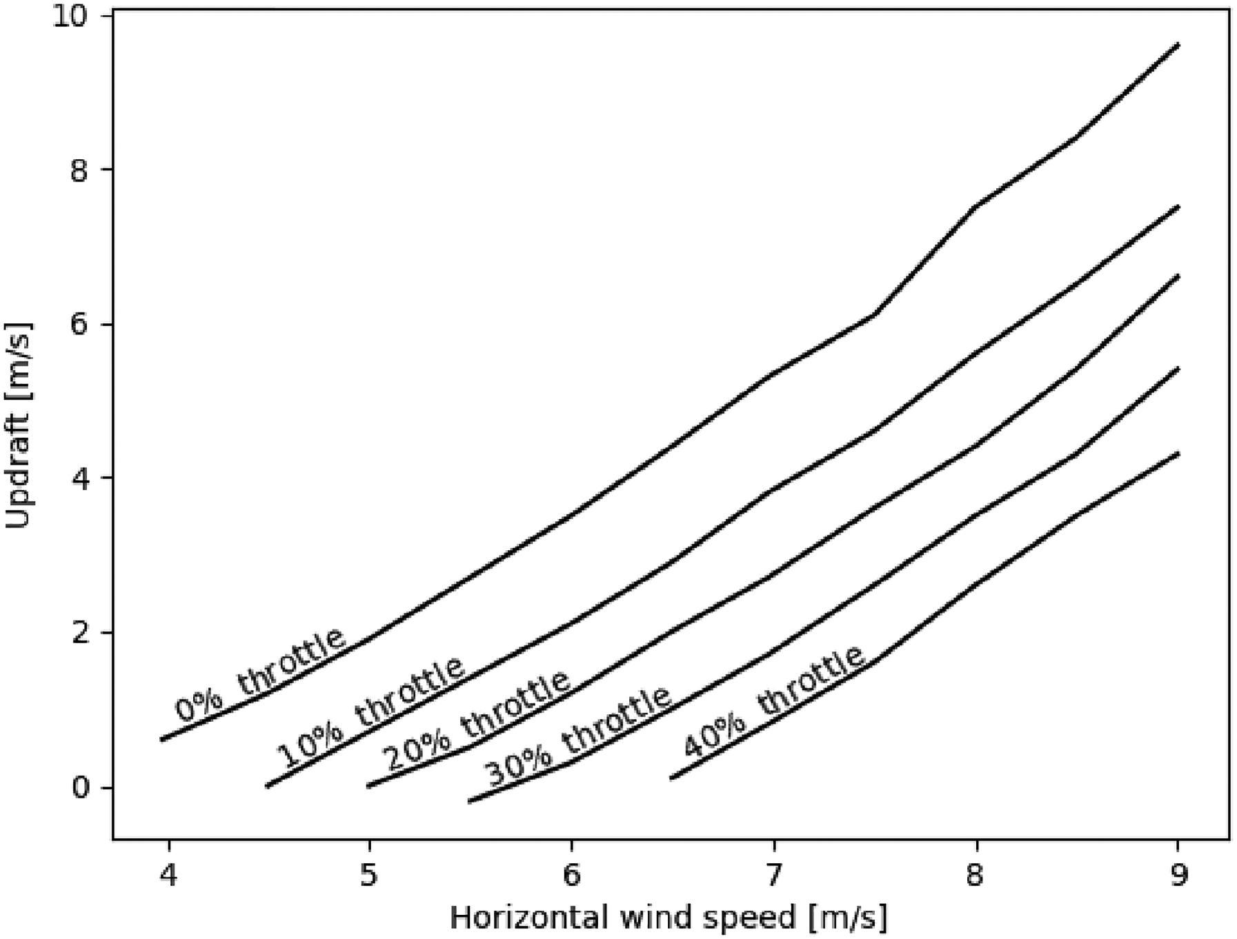
Average throttle consumption required by the UAV to hover on a given spot at a 5-metre accuracy for more than 5 min. Updraft and horizontal wind speed are set manually and are not coupled with each other.
The first thing that can be observed in Figure 9 is the fact that the UAV needs a minimum horizontal wind of 4 m/s to remain airborne. Below these speeds, the UAV was not able to maintain the same ground speed as the ship and flew away from the boat. Furthermore, it is noticeable that up to a wind speed of 7 m/s, the flight controller is able to soar autonomously in front of the boat without using any updraft. Consequently, increasing the wind speed beyond this point will result in the upper limit exceeding 0 m/s updraft and increasing even more with an increase in horizontal wind speed. The same applies to the 0% throttle curve. Increasing the horizontal wind speed will require a higher updraft to stay airborne without the usage of the throttle. Moreover, Figure 9 shows the minimal size of the region where sustained flight at 0% throttle is possible. While the UAV is able to hover at a large wind regime, only a smaller subset of this wind regime allows autonomous soaring without the usage of a motor. Furthermore, the required updraft increases significantly with an increase in horizontal wind speed. A wind speed of 4 m/s requires an updraft of 1 m/s for autonomous and throttle-less soaring. Doubling the horizontal wind speed to 8 m/s, however, requires already an updraft of 7.5 m/s.
Simulation discussion
As presented in the previous subsection, the simulation results consist of a set of different flight conditions and depict a couple of interesting phenomenons.
First, it was found that two cases exist that define the flight controller's boundaries. The lower case resulted in the UAV flying out of its flying region and away from the ship. This case could only be attained in case minimum throttle was reached. Increasing either the updraft or decreasing the horizontal wind speed ensured that the UAV lost track of its waypoint. The reason for this behaviour comes from the stall speed requirement incorporated in the Paparazzi energy loop. By decreasing the horizontal wind velocity, whilst following the ground speed of the ship, the desired airspeed reached values below the stall speed. The Paparazzi energy loop then overwrites the desired value of the flight controller and sets the desired ground speed such that the UAV flies at minimum stall speed. Similar reasoning applies to an increase in the updraft, resulting in a gain of potential energy, which has to be converted to kinetic energy to satisfy the altitude requirement. This produces a gain in airspeed and by such a gain in ground speed. In both scenarios, the UAV flies away from the ship. This case was also accompanied by an increase in altitude. The fact that the UAV is flying further away from the ship means we obtain a high x-axis error. To compensate for this error, the pitch controller pitches up. This results in a gain of potential energy and by such an increase in height. The lower case is thus due to an excess of either kinetic or potential energy. While the throttle can not be reduced any further to consume this overshoot in energy, an energy harvesting system could be implemented in the controller. This energy harvesting system would serve two advantages. First, flight at higher updrafts would be possible, and the lower limiting case would be shifted upwards. Second, harvesting the excess energy makes it possible to charge the batteries in flight and by such further improve the endurance of the flight controller itself.
The same applies to the upper case. Here the UAV either dives into the sea or crashes against the ship due to a decrease in the updraft or an increase in horizontal wind speed. The reasoning behind these manoeuvres comes from the fact that the UAV is flying at a high throttle already. A higher relative horizontal wind speed will result in an increase in drag. This leads to a lower ground speed. The natural reaction of the flight controller is to pitch down to transfer some potential energy towards kinetic energy. In case the horizontal wind speed is too strong, or the updraft is not strong enough, the UAV loses altitude and ground speed and hence crashes into either the ship or the sea. The same reasoning applies to a decrease in updrafts at constant wind speed. The decrease in updraft results in a loss of potential energy. This loss in potential energy is counteracted by a pitch up movement, translating kinetic energy towards potential energy. As the throttle controller is saturated already and no additional energy can be gained, the UAV is not able to satisfy its ground speed requirement and crashes into the ship.
The analysis of the feasible flying region has shown that a minimum horizontal wind speed of 4 m/s is required to remain airborne. This is traced back to the fact that the stall speed of the Parrot Disco is given by 8 m/s, and the ship was driving at 4 m/s. A minimum wind velocity of 4 m/s is thus needed to satisfy the stall speed requirement in case no updraft is present. Subsequently, it was shown that at horizontal wind speeds above 7.5 m/s, no feasible hovering conditions could be achieved without any updraft. This minimum required updraft is due to the need for available total energy to increase the airspeed beyond these horizontal wind speeds. The same applies to the minimum throttle case. While at a horizontal wind speed of 4 m/s a maximum updraft of 0.7 m/s was possible, at a horizontal wind speed of 7 m/s resulted in a maximum possible updraft of 5.5 m/s. By increasing the updraft, the UAV is able to harvest more kinetic energy from its available potential energy, and hence the flight controller is able to remain airborne at higher horizontal wind speeds. The final result obtained from the wind regime simulation confirmed that the throttle-less flying region is only a very small subpart of the actual feasible flying region. This is linked to the fact that autonomous soaring is a trade-off between kinetic and potential energy. To use 0% of throttle, the available potential energy by the updraft needs to be sufficient to generate enough kinetic energy to overcome the wind conditions. Too much potential energy, however, will result in the lower case and the UAV loses track of the waypoint due to either an excess of potential or kinetic energy. In the opposite case, decreasing the updraft and thus the potential energy at higher speeds results in the UAV requiring an additional amount of total energy. This energy is obtained by increased energy by either pitching down or increasing the throttle. Depending on the situation this will lead to an unsustainable flight condition and the UAV will either crash into the sea or into the boat.
In summary, the wind regime analysis has shown that autonomous soaring in front of a ship is nothing more than obtaining a certain amount of potential energy to hover at a given altitude, combined with obtaining enough kinetic energy to follow the ground speed of the ship. While the throttle controller is used to modify the kinetic energy exclusively, the pitch controller is used for trading kinetic energy with potential energy. Good positioning of the UAV in the wind field itself is then required so that neither an excess nor a shortage of total energy is available. While an excess of total energy only results in the UAV flying away and losing track of the waypoint, a shortage of energy results in the UAV either crashing against the ship or into the sea. The latter is thus the critical case that should be avoided at any cost.
The final behaviour of the flight controller in different wind regimes is shown in Figure 12.

Functional block diagram of the flight controller process during a change in wind conditions.
From this behaviour, it can be seen that the ship holds a couple of options to improve the hovering capabilities. As such, accelerating the ship speed will increase both the relative horizontal wind and the updraft. This can lead to better hovering capabilities at different positions. Depending on the relative position of the UAV with the ship, this can decrease throttle consumption. The updraft can be increased by changing the relative position of the UAV with respect to the ship, and in case too much horizontal wind speed is available, the ship can change its heading to decrease only the horizontal wind speed. Depending on the size and shape of the ship, similar updrafts should be generated.
Practical tests
This section first presents the results of the experimental tests and then draws conclusions based on the validity of the flight controller in the second subsection.
Experimental results
For the experimental results, the flights were mainly dependent on the weather conditions of the flight day. During the first flights, the main problem that persisted was a deviation of the UAV from its actual flight plan. This resulted in the UAV either crashing into the sea or the safety pilot taking over control. The problem was found to be a magnetometer error. Further investigation of the problem showed that the feasible soaring region was indeed too close to the ship. The metallic structure of the vessel interfered with the Earth magnetic field, and the UAV was not able to keep a constant heading anymore.
Instead of relying on the magnetometer measurements to obtain an accurate heading, GPS positions have to be integrated. This comes with the limitation that autonomous soaring under the current experimental conditions can only be performed in case the ship or target position is moving. In case the ship has no speed, the heading can not be calculated from GPS tracking. Minor movement across the GPS position is required in order to obtain a correct heading.
After that, the average wind velocity during the testing day was only around 3 m/s. This resulted in the ship having to cruise at the nearly maximum speed of around 8 m/s in order to obtain feasible soaring conditions. The results of the final flight are illustrated in Figure 10. During the experiment, the safety pilot intervened twice to reposition the drone to a new location with better soaring conditions. Furthermore, there were difficulties in tuning the roll controller, resulting in the roll angle being set by the Paparazzi energy loop instead of the roll controller. The last thing that should be noted is that even though a moving baseline GPS had been used, the moving baseline ground station was never able to provide an RTK fix and only a couple of minutes a DGPS fix was achieved.

Scatter plot illustrating the required throttle with respect to the position of the ship. Point S represents the position of the ship. Point O is the desired hovering location set by the safety pilot. Region A shows the optimal convergence of the flight controller. Here no throttle is required. Region B is too close to the ship and some of the updraft is already lost. Throttle is used to come out of this region. Finally, in region C, minor throttle is used due to climb setpoint requirements.
From Figure 10, one can deduce that the flight controller can reduce the throttle consumption significantly. Point O gives the actual waypoint that the safety pilot wanted to hover above. As can be seen in Figure 10, the flight controller is not able to maintain the y-axis position correctly. However, most of the time the flight the controller is able to fly at 0% throttle. Region A is a dense region of points in which the UAV was able to hover without any usage of the throttle for a large amount of time. Outliers of up to 30% throttle are detected in Region B. This corresponds to locations at a lower height where the UAV was too close to the ship. Region C depicts a mixed amount of scatter points in which the UAV was able to hover without throttle. At lower altitudes inside this region, throttle of up to 20% has been used a couple of times. The average throttle consumption for the whole flight is given by 4.5%. A minor linear distribution can also be seen in the scatter plot. On locations closer to the ship, the UAV prefers flying at higher altitudes, while at locations further away, the average altitude decreases. The flight had to be terminated after 15 min of autonomous soaring as the ship was leaving the predefined testing area.
Then, Figure 11 shows the throttle percentage of the UAV during the final flight test. The figure clearly shows that the UAV was able to fly without the usage of the throttle for most of the flight. Three major regions of higher throttle consumption can be identified. The first peak shows a region where the UAV lost several meters in height due to a decrease in the updraft. Then the UAV used the throttle to recover the altitude loss. The second peak has been identified at 500 s into the flight. Here the longitudinal position error has increased significantly. In this case, the throttle percentage was increased to reduce the position error. After that, a decrease in height is also observed. The last peak, starting at around 600 s into the flight, is a follow-up consequence of the second peak. Here a combination of both positive longitudinal and positive altitude error can still be observed. More details will be discussed in the next subsection.
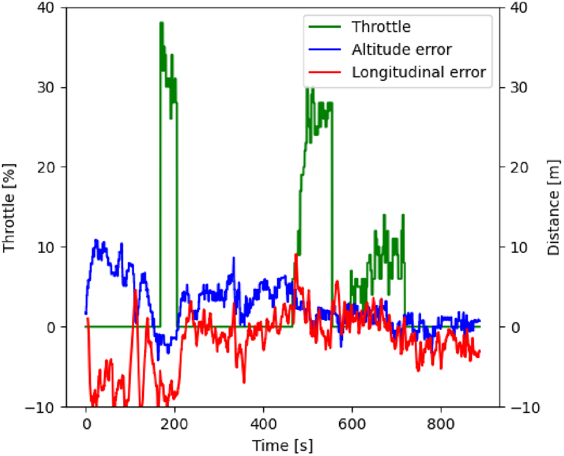
Throttle percentage of the UAV according to altitude and longitudinal position errors.
Experimental discussion
This section discusses the experimental test results and validates whether the flight controller is working as expected. First, it was detected that the magnetometer could not be used to calculate the vehicle heading. The successful autonomous flight has shown that using a GPS integrated heading is sufficient for a ground speed of 8 m/s. It is recommended to test the GPS heading at lower ground speeds. This can result in the heading jumping more drastically.
The throttle analysis showed that the experimental results are slightly worse compared to the simulations. While the simulated flight was able to achieve throttle-less, autonomous flight, the experimental flight had multiple outliers in the 30
Furthermore, a tendency to fly on a linear line from bottom left to top right has been detected in Figure 10. This has to do with the fact that the energy controller tries to increase its energy in case it is located too close to the ship, and decrease the total energy in case it is located further away. This behaviour is automatically induced by the fact that the updraft follows a linear line in front of the obstacle as well. At a lower altitude, the maximum updraft generated is positioned further away from the ship than at a higher altitude. As discussed in the Methodology chapter, the flight controller is designed to find an equilibrium position near a diagonal line that passes through the maximum updraft. While the exact placement of this diagonal cannot be proven using the tests performed in this research, the tendency of the controller to fly further away from the ship at a lower height (Region C bottom) and closer to the ship at a larger altitude (Region A) shows the tendency of the flight controller to follow this behaviour.
Figure 11 shows that the throttle was kept constantly at 0% except for three peaks. The first peak was accompanied by a decrease in altitude. The UAV lost too much altitude, and the flight controller started the throttle to avoid a crash into the water. The second peak was accompanied by an increase in longitudinal error. To overcome this error, the UAV started to pitch down to increase its kinetic energy. However, as not enough potential energy was available, the flight controller had to increase the throttle to avoid a crash into the boat. As a follow-up, the UAV was flying on low potential energy and with just enough kinetic energy. Until it was able to adjust both its kinetic and potential energy in the wind field, some throttle was enabled to sustain hovering flight.
Even though there were moments of using up to 30% of the throttle, the average throttle consumption was only 4.5% for the whole flight. This required a small amount of power from the battery. However, it should be noted that at an average throttle of 4.5% the propeller is barely spinning and thus providing no significant thrust. Further gain tuning should be sufficient to decrease these last percentages and allow throttle-less, autonomous flight at the given wind conditions.
Conclusion
A flight controller has been proposed which enables throttle-less and autonomous soaring in the wind field generated by a moving ship.
By balancing the total kinetic energy with the total potential energy, this flight controller is able to achieve autonomous flight at 0% throttle in the simulations. A practical test has confirmed that the throttle consumption can be decreased significantly in front of an emergency towing vessel. The flight controller was able to reduce the throttle consumption to an average of 4.5%. Successful hovering flight in the heavy wind conditions in front of the boat has thus been achieved using an energy control module that trades potential energy with kinetic energy using its pitch angle. The minor required throttle comes from the unfavourable wind conditions during the day of testing and the GPS propagation errors.
Using an equilibrium of both kinetic and potential energy, the flight controller enables autonomous hovering in a range of different wind conditions. Autonomous soaring without the usage of throttle is only possible for a smaller subset of updrafts at a given wind speed. Lower updrafts proved to be feasible, but the throttle consumption increased with a decreasing updraft. Wind speeds beyond a specific range showed that a minimum updraft is required to stay aloft. Furthermore, two prominent cases have been identified. The lower case resulted in the UAV flying away from its desired position due to stall speed requirements and an excess of energy. The excess of energy can, in turn, be harvested to avoid this flight behaviour and provide battery charging capabilities, for example. The upper case resulted in the UAV crashing against the ship or into the sea due to a deficiency in either kinetic or potential energy.
As such, autonomous flight in front of a ship makes it possible to change the wind conditions according to the current needs. Increasing the ship's speed will increase both the relative horizontal wind and the updraft. Depending on the relative position of the UAV with the ship, this can decrease throttle consumption. The updraft can be increased by changing the relative position of the ship with respect to the UAV, and in case too much horizontal wind speed is available, the ship can change its heading in order to decrease only the horizontal wind speed.
Future work is suggested to improve GPS accuracy by improving the current moving baseline RTK technology. Research in additional geolocation systems such as fixed cameras on the ship or ultra-wideband radio technology can also increase the positioning accuracy. Furthermore, it is recommended to perform further experimental tests at a range of different horizontal wind conditions. General gain tuning in these conditions will result in better performance. Next to that, research into different methods to calculate heading is suggested in order to allow stationary flight if the wind conditions allow for it. Some new manoeuvres, such as a dynamic soaring cycle could also be used to increase the available energy extraction. Research into the presented lower case at 0% throttle can also show whether excess energy can be harvested and whether the feasible flying region can be extended.