
Abstract
This paper presents an effective hybrid control approach for building stable wireless sensor networks between heterogeneous unmanned vehicles using long-endurance aerial robotic vehicles. For optimal deployment of the aerial vehicles in communication networks, a gradient climbing based self-estimating control algorithm is utilized to locate the aerial platforms to maintain maximum communication throughputs between distributed multiple nodes. The autonomous aerial robots, which function as communication relay nodes, extract and harvest thermal energy from the atmospheric environment to improve their flight endurance within specified communication coverage areas. The rapidly-deployable sensor networks with the high-endurance aerial vehicles can be used for various application areas including environment monitoring, surveillance, tracking, and decision-making support. Flight test and simulation studies are conducted to evaluate the effectiveness of the proposed hybrid control technique for robust communication networks.
Keywords
1. Introduction
In future wireless network-centric environment, teams of heterogeneous autonomous vehicles will be deployed in a cooperative manner to conduct wide-area sensing, surveillance, communication networking in a broad range of applications (Schoenwald 2000, Cortes 2004, Lee 2009). Coordinated autonomous operations by teams of heterogeneous vehicles such as aerial, surface, and underwater robots will increase the functionality of distributed sensing for shared situational awareness. In addition, sensor data analysis and integration would provide automated decision-making support, object detection, and mapping capabilities. The cooperative operations between the multiple autonomous vehicles using unammned aerial robotic vehicles as sensing and relaying agents are constrained by sensor range and communication limits, and operational environments (Pinkney, 1996). In principle, wireless mesh networking between the autonomous vehicles can provide wide area coverage, and video and sensory data for situational awareness and surveillance. Under this operational concept, unmanned aerial vehicle play an important role of long-range sensors as relay communication relay nodes. Stable communication networking between a distributed autonomous system (DAS) of networked vehicle and sensing nodes as well as autonomy of the unmanned vehicles will be key technologies for high-performance and remote operation in these applications. Challenging tasks for successful communication networking between the DAS using the UAV as the flying sensing and relay node include autonomous flight control, long operational range and flight endurance of the aerial vehicle to maximize the coordinated autonomous operations
The concept of communication relay using UAVs was proposed in the literature (Pinkney, 1996) where the UAVs are used as platforms for a high capacity trunk radio relay and battlefield broadcast systems. More research has been conducted on this type of the communication networks (Oh 2007, Zhan 2006, Frew 2008), but there are few flight experiments that have tried to realize this idea in actuality and succeeded in real test with flying aerial vehicles. Frew and his colleagues (Frew 2008) have conducted research on this topic and developed a Lyapunov guidance vector field (LGVF) based control algorithm that takes gradient inputs from a extremum seeking approach in order to control the UAV positioning to optimize communication links. While, in Ref. 7 (Zhan 2006), the optimal UAV position is calculated by maximizing the average data rate keeping the symbol error rate (SER) below a certain threshold. On the other hand, Lee and his colleagues (Lee 2009) have demonstrated successful flight experiments for high bandwidth communication networks between distributed multiple nodes using aerial vehicles as communication relay nodes. In those flight experiments, self-estimating extremum control techniques were developed in order to steer the aerial vehicles to obtain optimal flight trajectories which maximize wireless communication throughputs in terms of signal-to-noise ration (SNR) between ground user nodes and remote nodes.
The operational range of the unmanned vehicles, however, is usually limited by the communication range of communication systems. In addition, there are limited onboard energy power sources in small and micro unmanned aerial vehicles, which results in reduced endurance and range (Basu 2004). Typically, small or micro aerial vehicles have flight durations from to 1 to 2 hours even with advanced technology in the aerial platform design, thus it is required to develop advanced technologies to improve the flight endurance for small and micro aerial vehicles (Allen 2007, Edwards 2008).
The objective of this research aims at building robust wireless communication networks by using an autonomous aerial robot whose flight endurance is improved by harvesting convective energy from the atmosphere. For the purpose, there are two challenging issues to overcome to turn this idea into reality. The first issue is to how to control the UAVs to be located at optimal communication relay area, and second question lies on the method of extending flight endurance of the small aerial vehicles. As a solution to the first issue, optimal location of the small UAVs is calculated by applying a real-time optimal searching technique which is based on a self-estimating gradient descent numerical optimization approach (Lee 2009). The cost function used in the on-line optimization architecture for the UAV localization control is based on the signal-to-noise ratio (SNR) that is provided from an antenna propagation model developed. As an efficient strategy to achieve high endurance for UAVs, autonomous soaring gliders that extract energy from the environment by autonomously seeking thermal lift will be used with the proposed onboard soaring control technique (Andersson 2009). This extra energy will supplement the onboard fuel supplies and thereby extend the maximum endurance of the UAV. The technique is the same as glider pilots use to extend their time in the air. Studies have been conducted on the subject of using either static or dynamic soaring energy to sustain flight (Barate 2006, Allen 2007, Langelaan 2008), but a few have tried to realize this idea in actuality and tested it in flight (Allen 2007 & Andersson 2009).
In this paper, the soaring control technique tested by Andersson and colleagues (Andersson 2009) is utilized to extend the flight endurance of an autonomous UAV, which plays an essential role for keeping robust communication and data relay between distributed multiple users without loss of communication. A synthesized hybrid control technique which integrates two efficient control algorithms is proposed to obtain the goals. Initially, the motion of each UAV is controlled by the self-estimating adaptive gradinet controller (Lee 2009). This guides the UAV to reach the optimal location that provides the highest communication throughput. The autonomous thermal-seeking soaring control algorithm (Andersson 2009) is then executed to harvest energy to minimize the fuel consumption within a specified region. If the communication signal strength falls below certain threshold value, the control node is switched back to the extremum control mode. The overall concept of the hybrid switching control methodology is illustrated in Fig. 1.

Wireless Communication Networks between Nodes on the Ground and Mobile Nodes Using Long-Endurance Flying Vehicles
First, the performance of the proposed autonomous flight control based on the self-estimating gradient climbing approach is evaluated by conducting field experiments by measuring the received signal strength of the wireless links. Then the integrated hybrid flight control technique combining the soaring flight technique for extending the endurance of the flying vehicle is investigated through simulation studies with applications to reconfigurable wireless communication networks.
The remainder of this paper is organized as follows. Section II describes the overview of a hybrid control of a long-endurance unmanned aerial vehicle which uses a soaring flight technique to harvest lift energy from the natural environment. Section III describes the self-estimating extremum control technique for optimizing the flight trajectory of an uninhabited aerial vehicle to obtain a maximum communication links between multiple nodes. Section IV discusses the static soaring flight technique to extend the flight endurance of a small aerial vehicle. Section V presents flight test results. Finally, conclusion and discussion is presented in section VI.
2. Hybrid Control for Long-Endurance UAV Flight
The operational range of the vehicles is usually restricted by range constraints of the communication systems or limited endurance of the aerial platforms used. For data and communications relay tasks the endurance of the aerial platforms is of special importance to make these missions more effective. A hybrid control technique is developed for a stable communication relay with a small aerial vehicle with a switching supervisory system, and the concept is described in Fig. 2. The hybrid control is designed by integrating the self-estimating controller (Lee 2009) for a high bandwidth communication relay and the long-endurance flight controller (Andersson 2009) for a soaring technique for maximum flight endurance.

Hybrid Flight Control Architecture for Communication Relay with Thermal-Seeking Soaring Technique
Initially, the location of each UAV is controlled by the self-tuning extremum controller to steer an UAV to locate an optimal trajectory to guarantee high bandwidth communication links between a ground control center and a remote node. After the UAV reach the optimal location which provides a maximum communication throughput, an area is designated in which the UAV is allowed to execute the soaring control algorithm. The glider will fly inside the limited area in search for thermals and when a thermal is found the UAV tries to circle within the updraft to gain altitude. If the communication signal strength falls below certain threshold value, the control is switched back to the self-estimating control logic until the optimal communication-relay position is reestablished. This is done by using a supervision control system which has a decision-making capability, depicted in Fig. 2.

Flight Control for Soaring Searching with Spiral UAV Motion
As the autonomous soaring glider is commanded to execute the onboard soaring-searching control algorithm, the aerial vehicle is flying in a specific way where the flying pattern is a spiral of Archimedes. The spiral flying is for thermal searching within a specified area where the limit of the area is determined by a minimum threshold value of the communication signal strength as a SNR. The spiral flying pattern for thermal energy is illustrated in Fig. 3 where the flying center (◯ opt , ŷ opt ) is the estimate of the optimal location of an aerial vehicle and R SNR is the maximum searching radius, determined by solving a predefined threshold SNR value.
3. Autonomous Flight Control for Sensor Networks
In this section, we present autonomous flight control algorithms for aerial vehicle to build an ad-hoc communication sensor networks between aerial nodes and nodes on the ground.
2.1. Gradient Climbing Appraoch
Assume that the nonlinear dynamic and measurement model is given by

where

Consider a gradient based search method such as the steepest descent approach. Each iteration of a search loop computes a direction of the state. The search provides the following (Quarteroni 2002)
where
2.2. Extrem Seeking for Derivative-Free Gradient Estimation
When the analytical model of the loss function is not available or feasible to calculate the derivative of the function, a derivative-free gradient estimator, called the extremum-seeking (ES) approach(Ariyur & Krstic 2003), can be applied to calculate the gradient in a numerical way without analytical expressions. The ES algorithm is adaptive and model-free gradient estimator providing quantitative gradient value in a numerical way without requiring the mathematical model of the cost function. The typical architecture of the ES approach is composed of four elements, a high pass filter, a low pass filter, demodulation, and perturbation, as shown in Fig. 4.
For understanding of the architecture of the ES method, the brief mathematical description is introduced to explain how to estimate the gradient of a cost function. Suppose θ̂ is assumed to be the current value of the parameter, and asinwt is a small sinusoidal perturbation around θ̂. Then the output of the objective function is expressed by

where constant term in the output z is removed by applying a high-pass filter (HPF) as a differentiator

Demodulating z H with a sinusoidal signal sinwt divides the signal into a low-frequency signal and a high-frequency signal

Low-pass filtering of the demodulated the signal, ɛ, provides an estimate of the local gradient of J(θ)

The estimated gradient can be approximated in terms of the parameter change as
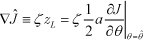
where ζ is a design parameter to be adjusted. The gradient estimate is then used to update the parameter by feeding back to a compensator to control the dynamic plant. More detail regarding the proof of stability and design guidelines can be seen in Ref. (Ariyur & Krstic 2003).

Extremum Control Architecture for Gradient-Estimating Approach With Derivative-Free Computation
2.3. Adaptive Gradient Climbing Control l
It is noted that for the case where the analytical differential model of the loss function or the gradient calculation is not feasible, the ES technique can be an alternative way to computing the gradient estimate in a numerical way. Based on the idea of the ES approach, an adaptive gradient climbing control method is designed by integrating the gradient climbing algorithm with the derivative-free numerical gradient estimator. The overall structure of the proposed self-estimating adaptive gradient climbing controller (AGCC) is illustrated in Fig. 5.

Adaptive gradient climbing control (AGCC) architecture with derivative-free gradient estimator
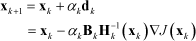
As can be seen in the above AGCC architecture, the estimated gradient of the cost function is obtained by applying the ES algorithm, and then a compensator can be designed for each specific control of a dynamic plant by taking the estimated gradient as an input. Finally, combing the ES gradient estimator with the gradient climbing control method, the derivative–free adaptive gradient climbing control can be expressed by

where ▽ĵ ∈ ℜ
n
denotes the estimated gradient of the loss function at time k, and
2.4. Autonomous Flight Controller with Heading Rate Control
Consider designing an autonomous flight control law with a heading rate command using the self-estimating gradient climbing (Lee 2009) which regulates the UAV to reach the optimal location by integrating the gradient-based hill climbing optimization algorithm with the gradient estimator.
Suppose that

where v ∈ ℜ1 is the ground speed and is assumed to be equal to the airspeed, T ∈ ℜ1 is the engine thrust, α ∈ ℜ1 is the angle of attack, D ∈ ℜ1 is the aerodynamic drag, L ∈ ℜ1 is the lift force, m ∈ ℜ1 is the mass of the flying vehicle, g ∈ ℜ1 is the gravity constant, γ ∈ ℜ1 is the flight path angle, φ ∈ ℜ1 is the bank angle, and ψ ∈ ℜ1 is the heading angle. Suppose that the altitude variation is not considered with the flight path angle close to zero, i.e., γ ≈ 0. The equations of motion of the flying vehicle reduce to the following planar motion

where u1 ∈ ℜ1 ≡ v and u2 ∈ ℜ1 ≡ (T sin α + L)sin φ / mv. For the case of the constant angle of attack with a small value, the equation of motion can be further simplified by

where κ ∈ ℜ1 is a bounded curvature. From the above equation, the control inputs

where the R is the radius of a curvature, and have the relationship with the speed and the heading rate, v/R = ψ̇. The heading is defined as the heading of the UAV with respect to the positive x-axis. The variations of a signal-to-noise ratio (SNR) performance function are a nonlinear function of several variables. In this paper, it is assumed that the UAV has a constant speed with constant level flight (ḣ(t) = 0, where h is the altitude above the mean sea level) and then the heading angle or bank angle is the only control variable with a heading rate command, u com (t) = vκ = ψ̇ com (t). Based on the fact that the components of the UAV position vector is an implicit function of the heading angle variable, that is, x(t) = f1(ψ(t)), y(t) = f2(ψ(t)), the cost function in the optimization can also be written as an implicit function of the heading angle only, J(x(t), y(t), h(t)) = J(ψ(t)), which reduces the multiple dimension of the gradient calculation to a scalar parameter.
Now, suppose that the characteristics of the figure of merit of the cost function is quadratic in terms of the heading angle variable, then the performance function can be expressed by

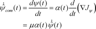
where J* is the maximum attainable value of the cost function, ψ* is the heading angle which maximizes the performance function, ψ̂(t) is the current heading angle estimate, and μ is the sensitivity of the quadratic curve which relates heading angle to the indicated SNR, and w(t) is a zero-mean white noise term which can be filtered out by applying a low-pass filter. It is assumed that the parameters which characterize the optimum values are unknown, but constant parameters. Taking a gradient of the cost function with respect to the current estimate ψ̂(t) provides the following

Taking a time derivative of the above gradient term again leads to

Finally, substituting Eq. (15) into Eq. (9) gives the heading-rate control input as
Note that the rate of the estimate of the current heading angle ψ̂(t) can be obtained from the method (Ariyur 2003) after applying the low-pass filter in the process of the extremum-seeking loop. At the final stage of the self-estimating extremum control approach when the UAV reaches the optimal location, it is necessary to make the UAV fly around the optimal set point rather than fly directly to the point or pass over the point. Thus a steady-state heading ψ̇ ss is introduced to guarantee that the UAV will orbit with a constant radius R ss at the final stage. The heading-rate command is expressed by
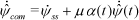
where ψ ss is a steady-state heading input to be selected and is related to a final approach circle radius, R ss = v/ψ̇ ss . Note that the time rate of change of the estimated heading angle is provided from the extremum seeking stage.
Finally, the control input u(t) ≡ ψ̂ com (t) to the UAV is expressed by

where ɛ ss is a criterion which guarantees the bounded motion of the UAV at the final stage. This heading control input regulates the UAV system to follow the ascending direction of the cost function value until the UAV reaches the maximum point of the cost function. Once the UAV gets close to the optimal set point, it switches to a steady-state heading control mode to orbit around the optimal point with a predefined constant radius.
The adaptive time-step scaling factor α k is computed by using a more intuitive method (Lee 2009) as

where ΔJk+1 ≡ Jk+1 - J k . This algorithm not only provides fast convergence properties but also reduces the unnecessary repeated circular motion of the UAV, which results from a direct searching mode to the optimal location.
2.5. Objective Function
In this section, a communication propagation model is used as a reference SNR signal for the inputs to a feedback controller based on a real-time self-tuning extremum control approach. The propagation model is also used to analyze the variation of free-space propagation loss, antenna pattern loss, and the effect of UAV orientation on the signal-to-noise ratio in the communication link (Rappaport 2002). The formula is based on Friis transmission formula, which is one of most dominant pass loss features affecting wave propagation in the radio channel.
The path loss model computes the path loss in dB between the UAV and ground relay nodes. The model for the path loss formula is based on Friis transmission formula and is expressed by


where f is a frequency in MHz and d(t) is distance in km.
The link budget model computes the received power, the signal-to-noise ratio (SNR) and link margin of the receiver. The equations for the link budget are given by (Rappport 2002)


where P
r
(dBm) is the receiver power, P
t
(dBm) is the transmitter power (28dBm), R
sen
(dBm) is the receiver sensitivity (−74 dBm), G
t
(dB) is transmitter antenna gain (14 dB), G
r
(dB) is receiver antenna gain (2.2 dB), L
p
(dB) ≡ (4π‖
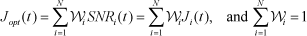
For multiple communication nodes, however, the cost function is defined with interactions between the multi-nodes, and it is necessary to satisfy the constraint. Straight forward method to define a figure of merit of the cost function is to calculate an average value by adding all of each SNR i function with a proper weight value W i
4. Autonomous Thermal Soaring Control
As mentioned previously, the UAVs that will be deployed as a part of this research require supplemental energy to extend endurance. To attain this increase, convective energy, or thermal updrafts, may be used to sustain flight. This section describes the process and conditions of thermal formation and presents the control functions of the autonomous soaring UAV.
4.1. Thermal Formation and Conditions
Thermal updrafts are formed when the sun heats the ground. As a result of that process, the air immediately adjacent to the ground is also heated. This causes a difference in air density which results in the ascension of the lighter air. These rising parcels can occur as continuous columns or separate pockets and if found by a bird or glider pilot, can be used to gain altitude to extend flight (Reichmann 1993, Pagen 1992). The basic requirement for thermal formation is solar radiation. It follows that thermals are directly dependent on surface heating, and are influenced by factors like topography.
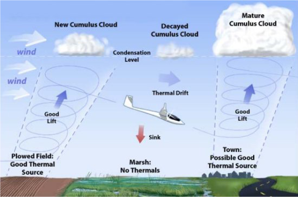
Thermal Soaring (aerospaceweb.org)
The lift provided by thermals offers an excellent opportunity for UAVs to improve endurance by sustaining continuous flight which is why it lends itself well to the purposes of the research presented in this paper. This approach is what normally is used by glider pilots to stay aloft. When an updraft is encountered the pilot begins to circle within the rising air, thus gaining altitude. When the desired altitude is reached or when the thermal no longer provides any useful lift, the pilot leaves the updraft and starts searching for a new one (Fig. 6).
The major challenges for this kind of soaring flight are to find updrafts, and once one is found, to stay within it and try to center on it as accurately as possible to maximize climb rate.
4.2. Auto- Soaring Control
To enable a UAV to exploit thermal lift, a guidance and control method for the vehicle is needed. This was made possible through the use of the auto-soaring algorithm described below which was loosely based on the work of Allen (Allen, 2007). It was implemented as follows: when switched to auto-soaring the flight is directed by the Simulink code, running on the onboard PC104. The code sends turn rate commands to the autopilot guiding the flight. In this case the glider will be either in search or soar mode. In search mode the UAV will follow a flight path defined by turn rate within the designated area. If the outer perimeter is reached, the UAV is turned back towards the designated area.
Auto-soaring and Detection algorithms
The algorithm has three central functions; search guidance, thermal detection, and thermal centering. The search guidance mode defines the flight path during search for lift and designates how the search for updraft is performed. The thermal detection mode monitors the energy rate of the aircraft and governs when to switch from search to soar mode and back. Once in soar mode, the thermal centering algorithm centers the vehicle in the updraft so as to gain altitude effectively.
Central to the detection of thermals, the triggering of soar-mode and the control of the UAV while tracking thermals is the vehicle's specific energy rate of change, Ė, and the vehicle specific energy acceleration, Ë. The vehicle total energy E tot (potential and kinetic) is given in Eq. (26) and is calculated using altitude h and airspeed V given by the static and dynamic pressure. The normalized energy E is given by


E is filtered to attenuate sensor noise in the input signals, and is then differentiated with respect to time to obtain normalized energy rate Ė. This energy rate essentially represents the climb rate compensated for the exchange between potential and kinetic energy. The normalized energy rate is differentiated to obtain normalized energy acceleration Ë.


To switch between soaring and search modes, Ė and Ë are monitored to decide when a sufficiently strong thermal is entered and when to start circling in it. To accomplish this, the “Mode Logic” of Allen was used (Allen 2007).
Centering Control
Once a thermal is found, the next challenge is to stay within it and to effectively use lift to gain altitude. To achieve the best climb rate the center of the circular flight path needs to be adjusted so that it coincides with the core of the updraft. The radius of the flight path also needs to be tuned depending on the size of the thermal.
Flying in the smallest possible radius would, therefore, seem to be the best strategy for soaring. However, smaller radius implies steeper bank angle, higher airspeed and an increase in sink rate of the air vehicle. To maximize the climb rate, a balance between bank angle and distance to the core of the thermal needs to be found.
The controller used for centering in this paper comes from the work of Andersson (Andersson 2009) and was derived from an efficient and widely used technique in manned aviation developed by thrice glider world champion Helmut Reichmann (Reichmann, 1993). The method of Reichmann was employed as a base for the thermal centering controller used in this paper. It was realized by applying a feedback control law where the normalized energy acceleration Ë was utilized to generate the turn rate command ψ̇ c to the onboard autopilot as

where k1 is the feedback gain and ψ̇ ss the steady state turn rate to maintain a constant climb rate.
In relation to Reichmann's technique, Ë is utilized to provide a representation for changes in climb rate. To compensate for latency in the feedback due to lag in sensors and filtering of feedback signals, Eq. (30) was modified to include a third term containing Ë, the controller is now given by

where k 1 and k 2 are feedback coefficients.
5. Aerial Robotic Flight Systems
The aerial platform used for the tests is based on a cross country glider, the SBXC, produced by RnR Products (RnR 2008) as shown in Fig 7. The UAV uses a Piccolo plus autopilot (Piccolo Documentation, 2008) for inner loop control, and the outer-loop autonomous soaring control runs on an onboard PC/104 (Microspace PC-104 (2008). For communication between the UAV and a ground control center, a Wave Relay (Wave Relay QUAD Radio Router, 2008) is used. This card provides access to a mobile ad-hoc wireless networks systems, which allows evey node on the network to communicate with other node. In addition to a 900 MHz wireless link dedicated to the safe operation of multiple UAVs from the ground control station, a second wireless communication link, the Wave Relay networking systems operating at a 2.4 GHz 802.11 mesh network, was added to the aerial vehicle. The radio is connected to a 3 dB omni-directional antenna mounted on the belly of the aerial robot for transmitting and receiving messages (Jones 2009). This features implies that the aerial vehicles could perform their cooperative tasks without connection to the ground control station (GCS). The layout of the architecture of those airborne components of the autonommous soaring aerial vehicle is described in Fig. 8 in detail, where the communication antenna can be housed inside the fuselage to minimize drag effects.
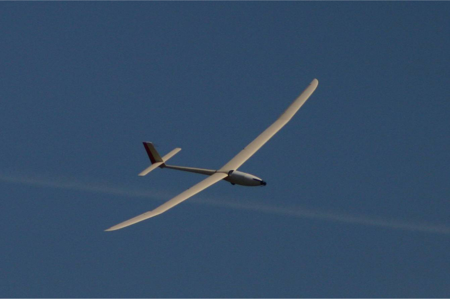
The RnR SBXC Glider Used for Flight Experiments

The Layoout of the Airborne Components of the Soaring Aerial Vehicle
Currently, the onboard PC-104 computer on the UAV is unable to extract the SNR value directly from the Wave Relay's management message. As such, the SNR value will need to be extracted on the Linux machine located at the ground station and sent to the local host computer prior to transmission to the onboard computer. The information flow for the SNR from the ground PC to the UAV is illustrated in Fig. 9. There is a switch on the local host computer which controls the type of SNR reading sent to the UAV. Currently, the switch caters for the following three types of SNR readings (Lee 2009) are available; First, model-based SNR, this SNR reading is generated using the mathematical SNR model based on the current position and orientation of the UAV. Second SNR reading is the actual SNR value observed by the Wave Relay radios. Finally, this SNR reading is based on the mathematical SNR model modified by the updated actual SNR reading from the Wave Relay radios by using a resursive least square method.
The ground segment includes 1) Piccolo Ground Station which manages the 900 mHz link to the Piccolo autopilot; 2) operator interface that runs on a standard desktop PC and 3) manual pilot console that is used for take o® and landing. In addition to the Piccolo operator interface, a Simulink GUI that connects to the onboard Simulink code simultaneously runs on the GCS desktop computer. The communication between the GCS Simulink GUI and the onboard PC104 is provided by the 2.4 GHz Wave Relay. The function of the GUI is to provide means to monitor telemetry, log data, adjust parameters, and switch settings in the onboard code during °ight. All the GCS equipment is accommodated in the Ground Control Station van, shown in Fig. 10.

Flight Test Systems for Extremum Control based on SNR Data

Groud Control Station Housed within a Rapidly Pack and Moving Van for Field Flight Experiments
To model the air craft described above, a six degree of freedom (6DoF) model of the UAV in Simulink was generated. This mathematical model required a number of aerodynamic/stability and control derivatives together with the mass moments of inertia with respect to the principal axis of the aircraft. The necessary aerodynamic and control derivatives were calculated using two different software packages, AVL (AVL, 2009) and Linair (LinAir v3.4, 2006). Both programs are based on the vortice lattice method and require the physical geometry of the air vehicle as an input file. In order to obtain an accurate model, the moments of inertia were experimentally obtained (Andersson, 2009). This was done by suspending the aircraft and letting it swing as a pendulum around the three principal axes (one at a time).
Thermal updrafts are known to vary greatly in size and shape and are therefore difficult to model accurately. However to be able to simulate the auto-soaring code, a model of thermals was needed. An updraft model developed at NASA Dryden Flight Research Center was used to model the updrafts used for the simulations (Allen 2006). An example of an updraft field created by the model is displayed in Fig. 11 below.
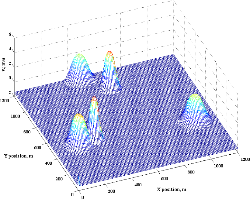
Updraft Field Created with the NASA Dryden Updraft Model
6. Flight Test and Simulation Study
The hybrid autonomous flight control algorithms combing the adaptive gradient climbing based flight control with the soaring glider control method are coded in high-level programming language using Simulink (MATLAB/Simulink, 2008). Both flight experiments and simulations studies were performed with two wireless communication nodes on the ground and an airborne relaying node mounted on an autonomous soaring UAV. First, the flight control law with the heading rate command using the adaptive gradient climbing approach for maximum communication link quality was tested in real flight experiment for robustness and effectiveness capabilities. Second, the integrated hybrid control algorithm with high endurance flight control technique is evaluated through simulation studies.
6.1. Flight Test for High Bandwidth Communication Networks
The real-time adaptive optimization algorithm which integrates a self-estimating extremum control algorithm to obtain an optimal UAV loitering location to maximize communication links quality between one UAV and two transmitting remote nodes is presented first. The communication links flight test was conducted as part of the TNT experimentation program (TNT-09-01) at McMillan Air Field in Camp Roberts, California on November 20, 2008. The two nodes depicted in Fig. 12 acted as the command station and the survey vehicle while the UAV functioned as the relay vehicle. The primary objective was to validate the designed onboard adaptive optimization algorithm that would drive the UAV to an optimal loitering flight path and maximize the SNR between the two nodes and the UAV. The aerial vehicle is equipped with 2.2 dB omni-directional antenna (HG2402RD-RSF).
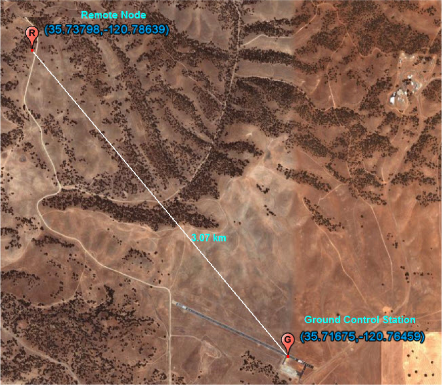
Relative Location of the GCS node and Remote Node [From Google Earth]

UAV Flight Path during the TNT Experimental Program
Fig. 13 shows the flight trajectory of the UAV during the test. Initially, the UAV was in a holding pattern orbiting north of the GCS node. When the control algorithm was activated, the UAV started to move in the direction of the steepest increase in the SNR value. When the UAV reached the region of peak SNR, a steady-state heading command was passed to make the UAV orbit around the optimal point. It was observed that the orbit around the optimal point was elongated and not a circular path. The circular lines shown in Fig. 13 are contour lines of constant SNR generated from the static SNR map in east-north coordinates for a stationary (non-dynamic) UAV with fixed altitude, heading, and bank angle.
6.2. Hybrid Control for Long-Endurance Flight
In this subsection, the performance of the proposed autonomous hybrid flight control algorithms for robust high bandwidth wireless communication relay functionality with the soaring aerial vehicle is demonstrated. The simulation study is composed of two phases; one is the high bandwidth communication links between multiple nodes where the autonomous guidance laws based on the self-estimating gradient climbing technique is executed to find an optimal trajectory of a relay UAV. The second phase is the soaring control mode where an onboard soaring control algorithm is executed to search updraft thermal energy to extend the endurance of the aerial vehicle with a specified spiral searching pattern as described in Fig. 3.
Fig. 14 shows the trajectories of a soaring aerial vehicle, which are generated from the hybrid supervisory control technique with application to the communication networking problem with two wireless ad-hoc sensor nodes. It is assumed that there is no packet loss and time delay effects on the communications among the nodes. The hybrid control approach consists of two phases. In the first phase, the optimal location of the UAV is obtained by using the self-tuning feedback controller resulting in converging to the line-of-sight intersection line (400 m in north and 200 m in east) between the two communication nodes. After the optimal communication links is established near to the optimal location, the second mode of the thermal searching is executed to find an updraft thermal energy to extend the endurance of the aerial vehicle. As can be seen in the Fig. 14, the UAV found a thermal energy, located in 470 m in north and 300 m in east in Fig. 15, with a spiral flying pattern. Based on the thermal energy detected, the UAV utilizes it to save onboard energy by obtaining soaring potential energy.

Simulation Results of Hybrid Control for Robust Communication Networks Using Long-Endurance UAV
Fig. 16 illustrates the variation of the total SNR cost value along with the trajectories of the soaring UAV. It is seen that the UAV reached an optimal location in 50 sec providing the maximum 32.5 dB SNR value. On the other hand, a thermal searching mode was executed around 30 sec later to harvest static thermal energy from the environment. After the soaring UAV found the thermal, the communication strength was drop to 32 dB, which satisfies the minimum threshold value.

Location of Updraft Thermal Energy

Plot of the Variation of SNR Value as Figure-of-Merit Cost
Fig. 17 describes the time rate of change of the SNR cost function in time where it is seen that the optimal location for high bandwidth communication links was established around 50 sec after the flight control command with the adaptive gradient climbing was executed with bounded convergence to zero value, and the UAV found a thermal energy in 220 sec later. In this way, the soaring UAV could establish the robust and maximum communication networks while the endurance of the small UAV could be extended dramatically, usually from 2 hours to more than 6 hours. Through the simulation studies, extended flight endurance of the soaring aerial vehicles makes the communication and data relay mission more effective and robust compared to that of the conventional aerial platforms.

Plot of the Time Rate of Change of SNR Cost Function
7. Conclusion
This paper described an efficient implementation of a reconfigurable ad-hoc wireless communication network between nodes on the ground and mobile nodes mounted on autonomous soaring aerial vehicles to increase the operational range of an end-node aerial robot or the communication connectivity between them. An efficient hybrid control technique is developed by integrating the adaptive gadient climbing based flight controller with the high-endurance flight technique for a reconfigrable high bandwidth wireles ad-hoc communication networks. The developed autonomous flight control algorithms based on the gradient technique drives the UAV to reposition itself autonomously in order to maintain an optimal loitering flight path to achieve the optimal communication link quality between two transmitting nodes. In addition, the effectiveness of the proposed integrated hybrid control architecture embedded with the soaring flight technique for the high flight endurance is evaluated. Extended flight endurance obtained by utilizing the hybrid flight control techniques makes the communication and data relay mission more effective and robust compared to that of the conventional aerial platforms.
8. Acknowledgements
This work was supported by Mid-career Research Program through the National Research Foundation grant funded by the Ministry of Education, Science and Technology (NRF-2010-0026391). The author would like to thank to Prof. Kil-To Jung for his valuable support and advice for this research.