
Abstract
The DelftaCopter is a tilt-body tailsitter unmanned air vehicle which combines a large swashplate controlled helicopter rotor with a biplane delta-wing. Previous research has shown that the large moment of inertia of the wing and fuselage significantly interacts with the dynamics of the rotor. While this rigid rotor cylinder dynamics model has allowed initial flight testing, part of the dynamics remains unexplained. In particular, higher frequency dynamics and the forward flight dynamics were not modeled. In this work, the cylinder dynamics model is compared with the tip-path plane model, which includes the steady-state flapping dynamics of the blades. The model is then extended to include the wing and elevon dynamics during forward flight. Flight test data consisting of excitations with a large frequency content are used to identify the model parameters using grey-box modeling. Since the DelftaCopter is unstable, flight tests can only be performed while at least a rate feedback controller is active. To reduce the influence of this active controller on the identification of the dynamics, one axis is identified at a time while white noise is introduced on all other axes. The tip-path plane model is shown to be much more accurate in reproducing the high-frequency attitude dynamics of the DelftaCopter. The significant rotor–wing interaction is shown to differ greatly from what is seen in traditional helicopter models. Finally, an Linear-Quadratic Regulator (LQR) controller based on the tip-path plane model is derived and tested to validate its applicability. Modeling the attitude dynamics of the unstable DelftaCopter from flight test data has been shown to be possible even in the presence of the unavoidable baseline controller.
Keywords
Introduction
Unmanned air vehicles (UAVs) have enabled new applications in many areas. 1 A wide range of those applications benefits from long endurance combined with vertical take-off and landing (VTOL) capability. Hybrid UAV combine the advantage of helicopter hovering and fixed-wing range efficiency. 2 One of the many concepts for combining long range with VTOL is the tailsitter or tilt-body hybrid UAV. 3 This concept has its rotors pointed upwards during hover, but can tilt downward by 90° to transition to forward flight. During forward flight, the wing provides the required lift, while the rotor only counters the drag.
Many tailsitter concepts have been proposed. Using at least four rotors in hover combined with traditional multicopter control is the earliest and most common solution. Examples include the QuadShot 4 and the VertiKUL. 5 A dynamic model for such a platform has been proposed by Smeur et al. 6
Reducing the number of rotors, Bataillé et al. 7 have proposed two counter-rotating in-line propellers on their Vertigo platform. The counter-rotating small propellers reduce the gyroscopic effects of the propellers on the body to levels where it does not need to be compensated for by the attitude controller. Similarly, when both propellers are in-plane but side by side, the gyroscopic effect of both counter-rotating propellers cancel each other out pretty well. This was for instance shown in the control of the MAVION by Lustosa et al. 8 and the Cyclone by Bronz et al. 9 Wong et al. 10 have proposed a similar concept but with variable pitch propellers, and show that a controller based on a simple second-order model achieves acceptable control. But for all three, the biggest difficulty was coping with the highly non-linear and imprecisely modeled effectiveness of the aerodynamic control surfaces.
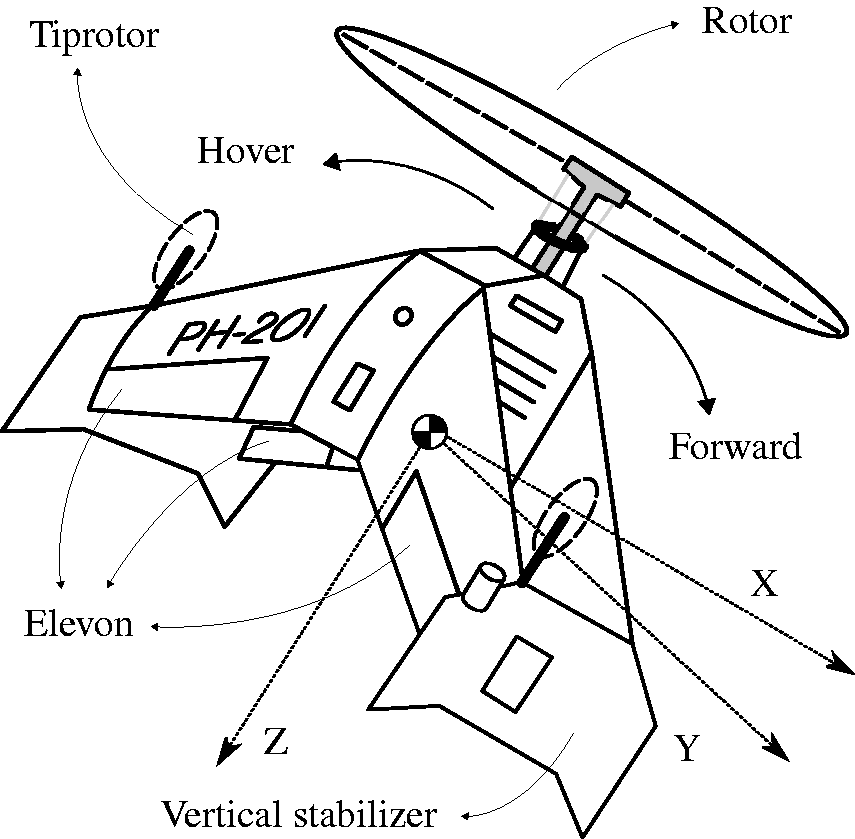
To further increase hovering efficiency and control moments, De Wagter et al. 11 have proposed the DelftaCopter tailsitter (see Figure 1) which has a single rotor with cyclic and collective blade pitch control. The rotor inertia of the DelftaCopter was shown to be sufficiently large to significantly affect the dynamics of the rigid body, yet is too small to act as a pure gyroscope as in a conventional helicopter described by Kondak et al.12 The proposed model allowed to create a working controller, but only modeled the low-frequency dynamics in hover. 13 Several other single rotor concepts were proposed like the AeroVel Flexrotor, 14 but these do not report the same properties as the DelftaCopter.
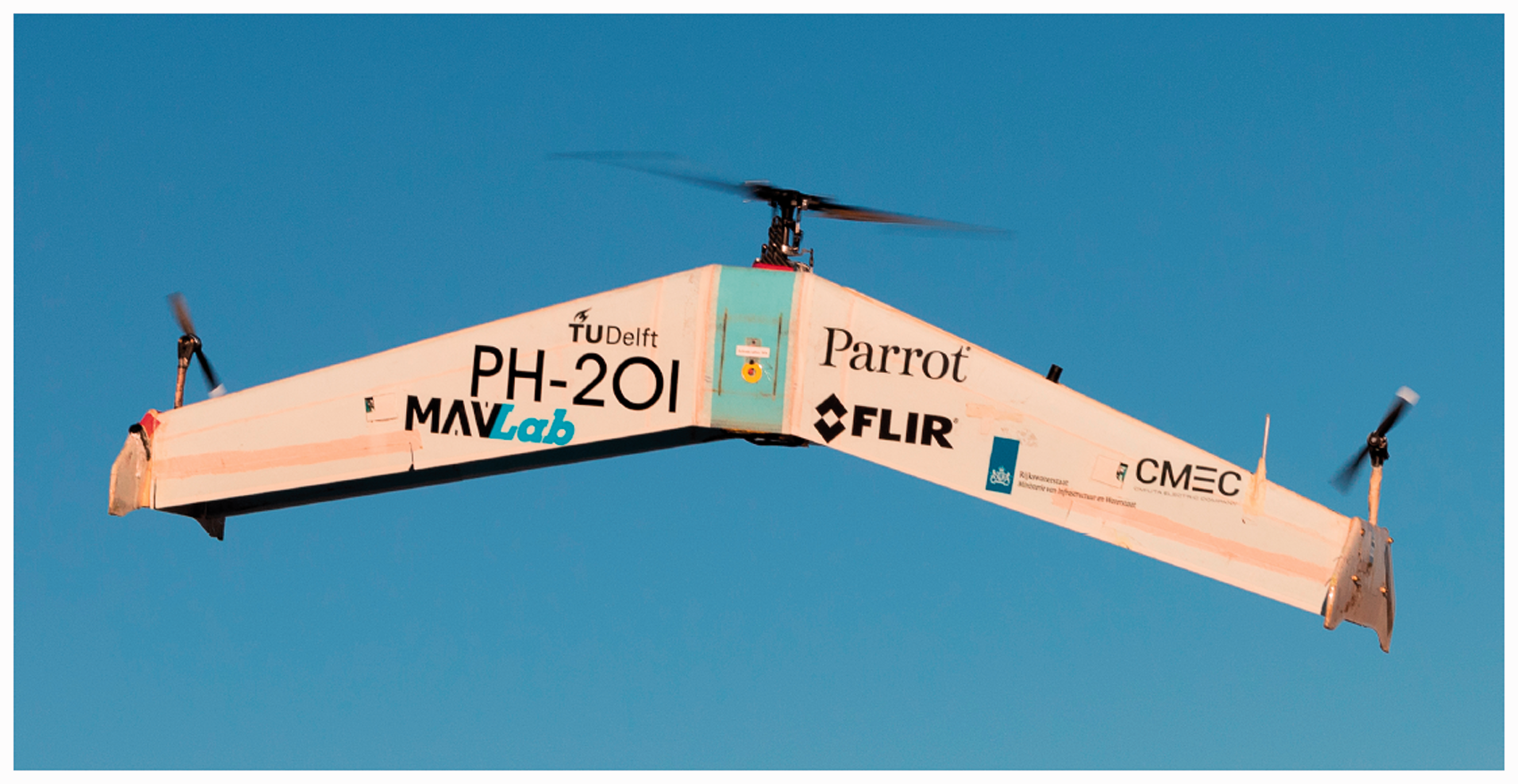
The DelftaCopter tailsitter UAV in hovering flight. DelftaCopter has a single large rotor with collective and cyclic blade pitch control, two small torque countering tip propellers and a pair of delta-wings placed in biplane configuration. The tips form the landing legs and provide yaw stability in forward flight. It weighs 4.3 kg and was designed to fly 60 km in the Outback Medical Challenge 2016. 15
While black-box modeling has recently shown practical results in modeling unconventional UAV, 16 this work will extend a model of a tailsitter UAV with a single large rotor to better model high-frequency responses and forward flight and will use grey-box parameter estimation.
The section “Single Rotor Tailsitter Modeling” first compares the different models that can be applied to single rotor tailsitters, and the section “State-Space Description” formulates the state-space model. The section “System Identification” describes how system identification is performed in-flight on an unstable platform. The section “Identification Results in Hover” describes the results of the system identification. With the fitted models, a controller was designed and implemented for hover in the section “Model Verification through Controller Derivation”. The model is extended to model the forward flight dynamics in the section “Forward Flight Modeling”. Finally, the conclusions are presented.
Single rotor tailsitter modeling
Modeling helicopter rotor dynamics can be categorized into roughly three levels of simplification in blade flapping dynamics.
Flapping dynamics
The first and most elaborate approach is to deal with the blade flapping explicitly and to include the flapping angle of every individual blade as a state of the model. This requires many physical parameters to be accurately identified.
Bramwell et al.
17
proposed such a model where θ is the blade pitch angle, Ψ is the in-plane rotation of the blade from the back of the helicopter and θ0 is the collective pitch angle. δx and δy are the cyclic pitch settings and influence the blade pitch through the swashplate as follows

This variation of pitch angle θ over the rotation Ψ from equation (1) will generate differences in aerodynamic forces which, combined with aerodynamics and inertial forces, in turn make the blades flap up and down.
Tip-path-plane
A first simplification is to relate the attitude dynamics of the helicopter to the tip-path plane (TPP). This is the plane in which the tips of the rotor travel and is shown in Figure 2. Mettler 18 has derived a TPP model by neglecting high-frequency dynamics of the rotor. The TPP is represented by the longitudinal and lateral angles a and b in radians between the TPP and a plane perpendicular to the rotor axis. These correspond to the steady-state flapping angles when the blade is aligned with the X and Y axis. The TPP angles change under influence of control inputs, rotations of the fuselage and gyroscopic precession of the rotor. The fuselage is a separate rigid body and a moment is transferred from the rotor to the fuselage if the a and b angles are non-zero, due to the effective spring between the rotor blade and axis and the offset of thrust application point on the rotor and the center of mass of the fuselage.18,19

Helicopter tip-path plane (TPP) model showing the tip angles a and b, the cyclic deflections δx and δy as well as the body X, Y and Z axes and p, q and r turn rates. Ω is the rotor speed.
Cylinder dynamics model
A final simplification is to ignore the flapping dynamics completely and treat the rotor as a rigid disc or cylinder. This model is widely used for small helicopters.20–22 A TPP model can be transformed into a model without flapping dynamics by setting the derivatives of the a and b angles to zero. This simplification can be valid if the inertia proportion of the fuselage compared to the rotor is very small or the hinge spring forces are very large. 19 The model without flapping dynamics is referred to as a cylinder dynamics (CD) model.
State-space description
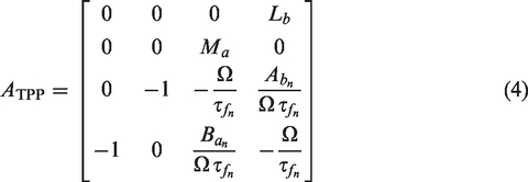
The TPP and CD models will be given as linear time-invariant models in state-space form


TPP model
The TPP model has been adapted from Mettler.
18
Only the attitude dynamics are considered and the Hiller bar dynamics are removed. The state vector becomes


CD model
The CD model state variables are only the body rates


Relation between CD and TPP
In Mettler’s model, only the a and b states drive the angular accelerations in q and p states, respectively. This means that instead of determining the body angular acceleration directly using the control input as in the CD model, control inputs first affect the dynamics of the TPP, which, in turn, influences the body angular acceleration.
The steady-state solution resulting from
System identification
Unstable platform
To identify the parameters from the derived models, a grey-box parameter estimation procedure is used based on the input–output response found in flight test data. To get the best identification results, the system should be measured open-loop. In the case of the DelftaCopter, this is not possible because it has an unstable attitude and requires at least a rate controller to fly. Constraining the motion to one axis at a time is not an option as the rotor dynamics create couplings between pitch and roll that would then not be identified. Initial attempts by hanging the DelftaCopter using a rope introduced too many external forces on the system and made identification impossible. Therefore, system identification was finally performed in free flight using a simple linear P feedback controller on rate. The controller used during system identification is a simplified version of the one described by De Wagter and Smeur
13
in which the rate coupling compensations are removed

Noise
To lower the risk of false correlation between different inputs and states that become coupled through the attitude controller, Tischler and Remple 23 suggested adding white noise to every axis independently. This reduces the chance of false correlations and hereby allows in-flight system identification of an unstable platform if a simple baseline controller is available.
Finally, further complicating system identification, not all states can be measured in-flight. As represented in the C-matrix in equation (6), only the body rates can be measured and the a and b states are not directly observable. Absolute values of a and b are thereby not validated.
Flight maneuvers
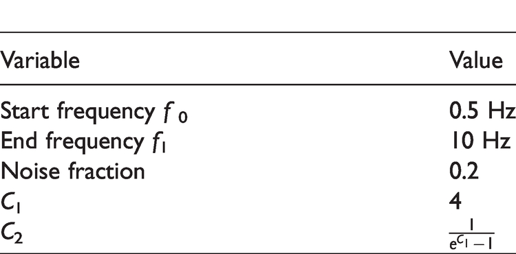
Flight tests were performed in an indoor environment without wind or turbulence. As proposed by Tischler and Remple, 23 a “chirp-shaped” actuator deflection is applied on each control input separately. A chirp is a sine wave with a frequency increasing continuously over time.
The white noise that is also injected on all axes during the chirp is filtered with a first-order low-pass filter with the cut-off at the highest frequency of the chirp. An exponential-time chirp is used to have enough content at the lower frequencies.
The chirp signal is generated and added to the controller signal and the resulting actuator signal is stored with the gyroscope measurements on an SD-card at a frequency of 512 Hz using a custom Paparazzi-UAV autopilot. 24
The exponential-time chirp formulation by Tischler and Remple
23
was implemented as
a


Exponential-time chirp settings.
Post-processing
To cope with low-quality sensor data, some post-processing was performed as in Dorobantu et al. 25 The onboard flight test data were filtered digitally using an ideal low-pass filter with a cut-off frequency of 15 Hz. This removes vibrations caused by the DelftaCopter rotor which rotates at about 27.5 Hz. The inputs were centered around zero to remove any input bias. The resulting time domain chirp logfiles were used to fit the parameters using the MATLAB b system identification toolbox greyest function.
Identification results in hover
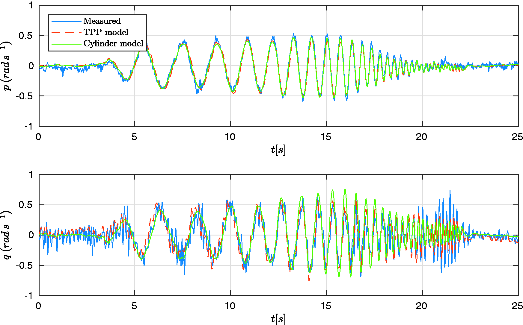
The full-time sequences including fitted models for a roll chirp are shown in Figure 3. The figure shows the measured pitch and roll rates together with the predicted pitch and roll rates from both CD and TPP models. The predicted pitch and roll rates are obtained by feeding the logged inputs into the respective models. The non-zero pitch rate q is a result of the pitch–roll coupling introduced by the rotor. It is clear that the CD model can accurately predict the response up to a certain frequency, but does not include the eigenfrequency which is excited at around 28.5 s. The TPP dynamics model has four states and was found to have two pairs of complex poles which leads to two eigenfrequencies. The slowest eigenfrequency is the same as in the CD model, while the highest eigenfrequency corresponds to the faster oscillations seen in the chirp plots. A pitch chirp is shown in Figure 4. In this chirp, the mismatch between the CD model and measurements is even worse.

Chirp on the roll axis in hover. The very significant pitch response to the roll chirp is mainly due to pitch–roll couplings. The TPP model is much better at reproducing the measured pitch signals in the higher frequency range.

Chirp on the pitch axis in hover. The roll motion due to pitching is not severe due to the high roll inertia compared to the pitch inertia. The CD model accuracy at low frequencies is clearly worse than the TPP model.
Validation maneuvers
To validate the identified model parameters, pitch and roll doublets were recorded separately and not used in the identification. Figure 5 shows pitch and roll commands manually given by a pilot, which represent normal flight maneuvers of the DelftaCopter. While the roll rate is relatively well captured by both models, even at these relatively low-frequency doublets, the pitch rate is significantly off in the case of the CD model.

Validation flight test sequence flown in manual control consisting of first a roll doublet and then a pitch doublet. The roll response is quite accurately modeled by both models, while the pitch response is clearly better in the TPP model.
Table 2 shows the eigenfrequencies of both identified TPP and CD state-space systems. The first pole-pair has almost the same eigenfrequency in both models, which means that at lower frequencies both models respond comparably. However, the higher eigenfrequency of the flapping dynamics model is not present in the CD model, which explains why high-frequency dynamics are completely damped out, as is most obvious in Figure 4.
Comparison of eigenfrequencies of the TPP and CD models.

CD: cylinder dynamics; TPP: tip-path plane.
Results
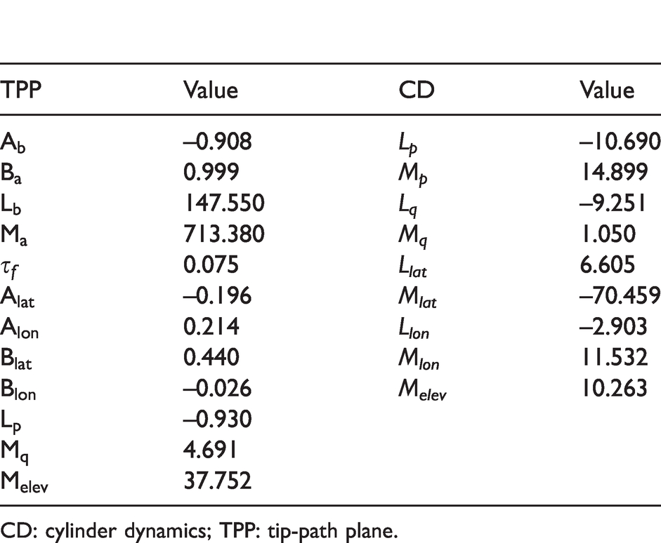
Table 3 lists all the identified model parameters. These are the matrix elements in equations (4), (5), (7) and (8) where the following substitutions were performed


The identified TPP and CD model parameters.
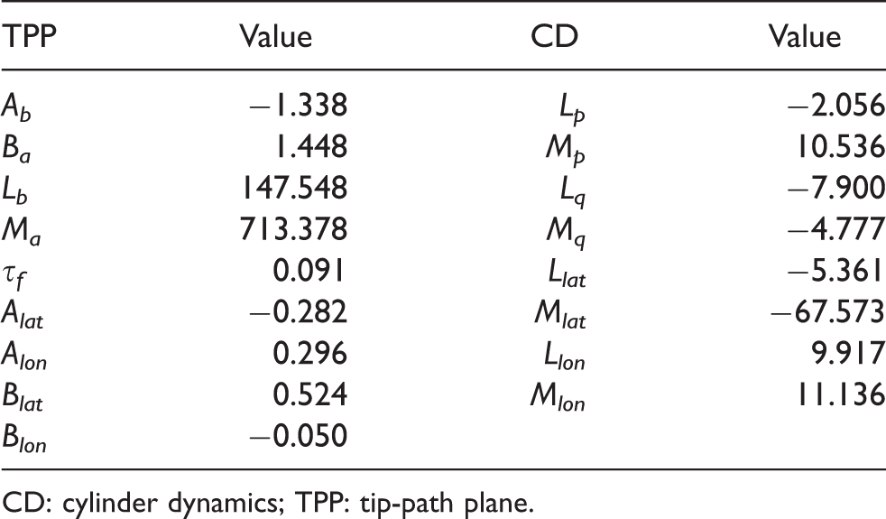
CD: cylinder dynamics; TPP: tip-path plane.
The difference in roll and pitch inertia of the DelftaCopter is apparent from the Lb and Ma values, which differ by a factor of 4.8.
Fitting quality
To assess the fitting quality, the coefficient of multiple correlation (CoMC) is used as given in equation (15), where 100% constitutes a perfect match

CoMC of the TPP and CD model fits on identification chirps and validation doublets.

CD: cylinder dynamics; TPP: tip-path plane.
Reproducibility
To validate that the parameters were not overfitted to a particular chirp, the TPP model was fitted to two different sets of chirp data and their fitted parameters were compared. The highest single change in model parameter between the two sets of chirps was 7.7%, but the eigenfrequencies and damping ratios of the systems differed not more than 0.9% and 1.8%, respectively.
RPM dependence of parameters
The model from Mettler et al. 19 which is simplified in equations (4), (5), (7) and (8) contains the rotor r/min Ω and is expected to compensate changes in rotor speed. To assess if the remaining model parameters remain constant at different rotor rotational speeds, a range of r/min between 1500 and 1650 was tested.
Although the rotor r/min was varied only 10%, some model parameters, which should stay constant, showed changes of up to 185% (Blon) with many others changing tens of percents as shown in Table 5. The meaning of these changes in model parameters in terms of model response is analyzed by comparing the eigenfrequency and damping of the model fitted on the 1650 r/min data with the model fitted on 1500 r/min and then corrected to 1650 r/min using equations (12) to (14). The largest change in eigenfrequency was only 4%, while the largest change in damping ratio was up to 28%. This leads to the conclusion that mainly the damping properties still contain unmodeled dynamics. The CoMC of this model fitted on 1500 r/min was 72.4% in roll and 67.1% in pitch when tested on the same 1650 r/min chirp as in Table 4. Further research is thus needed to obtain models that generalize well with different rotor r/mins.
The identified TPP parameters in function of r/min.

Model verification through controller derivation
To test the applicability of the model, it was used to derive a linear rate controller which was subsequently tested. Since the TPP angles a and b are not measured onboard the DelftaCopter, a linear observer was created in the form


The L matrix is chosen using pole placement, setting the poles of the observer at
The controller is designed using the feedback law


The gain matrix K is selected using LQR. This finds the optimal gain matrix K for the system minimizing a cost function of state and inputs. The cost matrices of the LQR design for the states p and q is set to 1. Since the actual value of the a and b states do not matter, they were given a cost of only 0.001.
Several controllers were then designed with different costs on system input deflections. The lower the cost on the input, the larger the allowed deflections and the faster the controller steers the system. The input cost of 5 made the system the fastest without introducing oscillations.
The controlled system response is shown in Figure 6. It can be seen that the roll response has a small delay, but the roll measurement follows the command well. The pitch response shows a coupling when larger roll rates are present. The pitch response is also larger in magnitude than the commanded rate.
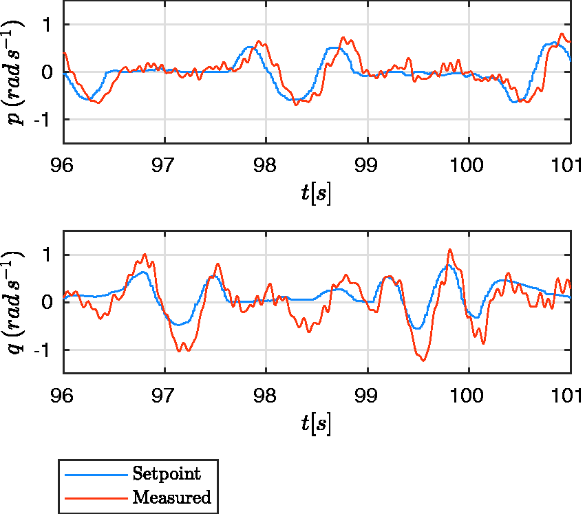
Performance test of an LQR controller derived directly from the identified TTP DelftaCopter model. The pilot manually commands the attitude rate of the DelftaCopter. The roll response has a small delay with respect to the command but otherwise has adequate tracking performance. The pitch rate shows coupling with the roll and the response shows larger values than the command.
The fact that the model can be used to design a controller for the DelftaCopter further confirms that the TPP model covers the most essential dynamics of the platform. On the other hand, it confirms the findings in Table 4 that not all DelftaCopter dynamics are captured in this simplified model.
Forward flight modeling
In forward flight, the DelftaCopter pitches down 90° such that the wings are almost level with the ground, as shown in Figure 7. The airspeed increases and the wings generate the required lift to maintain altitude, while the main rotor is now providing forward pointed thrust.
The DelftaCopter tailsitter UAV has a single main rotor which points up and provides lift during hover. Two tip props provide counter torque in hover, and the swashplate gives lateral and vertical control. In forward flight, the entire vehicle tilts 90° down and the rotor provides thurst while the biplane delta-wings provide lift, and the elevons provide most of the control. In forward flight de tip propellers are disabled.
In fast forward flight, the aerodynamic surfaces play a significant role in the balance of moments of the DelftaCopter attitude dynamics. The TPP and CD hover models are therefore extended. To keep a linear model, linear aerodynamic moments are assumed.
Aerodynamic surface models
The DelftaCopter has four movable surfaces that together perform the role of aileron and elevator of the delta-wing. The ailerons apply a moment on the body along the Z axis, which is the axis of rotation of the rotor and points forward during forward flight. Since the yaw angle is not included in the model and differential aileron drag of the ailerons is further neglected, it is not added to the model. The elevator can generate a significant moment in the pitch axis and is included in the model as parameter Melev. The longitudinal damping moment of the wings due to a pitch-rate q is named Mq and lateral damping due to rate p is called Lp. Note that for the DelftaCopter, the body X axis point down and represents the yawing of the delta-wing. In the CD model, these extra effects are lumped into the parameters already present, while in the TPP model these damping parameters need to be added. The state vector x is the same as the model in hover, while the input vector is extended to
The resulting TPP state-space system for forward flight thereby becomes


Lp and Mq represent aerodynamic damping on the roll and pitch rate. As before, the parameters Lb and Ma of the TPP model are the representative spring constants, and their physical meaning is given by Mettler,
18
sec. 3.1. Ma is defined as

This relates the TPP angle a to the angular acceleration
The
Results
The parameters are fitted from measurements obtained during chirp maneuvers on all three actuators
The parameters of the TPP and CD models are given in Table 6. Comparing these with the hover parameters in Table 3 shows that both have comparable parameters for the rotor dynamics in the TPP model. That the roll rate damping is very small is to be expected since the vertical stabilizing tips of DelftaCopter have a small moment arm to the center of mass.
The fitted values for the TPP and CD models in forward flight.
CD: cylinder dynamics; TPP: tip-path plane.
Figures 8 to 10 show the measurements and the model responses of chirps on roll, pitch and elevator, respectively. The resulting TPP and CD model fits are overlayed in the figures and clearly show which frequencies are not well modeled.
Validation chirp on the roll axis in forward flight. The pitch motions are mainly due to pitch-roll coupling. The TPP and CD model have a similar response. The high-frequency fluctuations in the pitch are due to the attitude controller which is active during the chirp.

Validation chirp on the pitch axis in forward flight. The CD model accuracy is much worse than the TPP model, while the latter is also unable to follow the measurements at higher frequencies.

Validation chirp on the elevator axis in forward flight. The roll response p (yaw in fixed wing aircraft reference frame) is fitted accurately by both TPP and CD models, while in the pitch reponse q, the TPP models starts to show significant difference around 20 s as the CD model is unable to replicate those frequencies at all.
It is clear that the TPP model is better at predicting the high-frequency response than the CD model, but the fit is not as good as for the hover model. This can be due to the r/min fluctuations or the TPP model. Another cause of model inaccuracy could be aerodynamic effects missing in the model or the energy exchange during the chirps. Atmospheric conditions are also less steady during outdoor forward flights than during the indoor hover tests. The angle of attack is not part of the model either and was not measured, but could have an important influence. Surprisingly, the Mq parameter is positive, implying a positive feedback loop on the pitch rate. This could be due to the missing of other influences in the model. The CoMC of the fits can be found in Table 7. Both fitting and validation percentages concern three chirps, one roll, one pitch and one elevator. The validation chirps and model responses can be found in Figures 8 to 10.
Comparison of CoMC percentage as given in equation (15) for forward flight.

CD: cylinder dynamics; TPP: tip-path plane.
Conclusion
The DelftaCopter is a tailsitter UAV consisting of a single rotor with cyclic and collective pitch control on top of a delta-wing biplane. Previous research developed a CD model which assumes a rigid rotor. 13 This work compared the CD model with a linearized TPP model of the attitude dynamics based on work by Mettler. 18 A system identification modeling approach was chosen and chirps were used as system identification maneuver to fit a wide frequency range. The TPP model is shown to be much better at modeling the high-frequency response than the CD model. This is validated using manually flown doublets, for which the TPP response also shows better accuracy. In particular, the flapping dynamics modeled as the TPP significantly influence the pitch dynamics of the DelftaCopter at about 5 Hz. It was shown that this model can be used for controller design by deriving an LQR attitude rate controller.
The relationship between the identified parameters and rotor r/min was found to be different than predicted from theory. This may be due to the lumping together of unmodeled effects into the present parameters, but is likely to be due to non-linear effects that the current state-space model has linearized. In particular, the rotor hinge spring is believed to have very non-linear characteristics.
For forward flight, the TPP and CD models were extended to include roll rate and pitch rate damping and to include a constant for the elevator effectiveness.
Some very particular characteristics of the DelftaCopter were also confirmed:
The principal components for the actuation of pitch and roll are significantly different than in traditional helicopters and are not even perpendicular. The roll actuator mainly drives roll at low frequencies and mainly drives pitch at high frequencies.
Overall, the derived linear state-space model captures most of the dynamics of the DelftaCopter in the frequency range up to 10 Hz. Nevertheless, the data clearly shows that not all dynamics are modeled and more states and non-linearities have to be included to improve the modeling.
Recommendations
Due to technical constraints, the a and b angles of the TPP could not be measured. They were estimated using the derived model, but could not be validated. The angle of attack α or sideslip angle β of the delta-wing in forward flight could also not be measured, but could better model errors like the end of Figure 10 where sideslip or increased angle of attack could be the cause of the steady-state error.
Although separate tests have shown that the used MKV HV9767 servos could track the required chirp commands with small deflections up to frequencies of over 20 Hz, the role of servo dynamics on the faster dynamics should be further investigated.
The dependency of model parameters on r/min needs further investigation as the expected theoretical relation could not be confirmed.
Finally, in forward flight, it is recommended to generalize the flight model for different airspeeds and r/min, as these values do change during normal flight conditions.
Footnotes
Acknowledgements
The DelftaCopter was designed and built by a large team over many years. This work would not have been possible without the contribution of every one of them.
Declaration of conflicting interests
The author(s) declared no potential conflicts of interest with respect to the research, authorship, and/or publication of this article.
Funding
The author(s) received no financial support for the research, authorship, and/or publication of this article.