
Abstract
This paper presents the design process and experimental results of a brand new flapping and trailing edge control mechanism for a flapping wing micro air vehicle. The flapping mechanism, whose main components are fabricated from string, is suggested and optimized further by a modified pattern search method. The trailing edge control mechanisms for pitching and rolling moments are designed to be attached onto the present flapping mechanism in a modularized fashion. Prototypes of both mechanisms are fabricated and experimentally tested in order to examine the feasibility of the designs. It is expected that the present flapping mechanism will generate enough lift for the total weight of the vehicle. The present control mechanism is found to be able to supply sufficient control moment.
Introduction
Up to now, biologists and aeromechanical engineers have suggested a bunch of designs for flapping wing unmanned air vehicles (FWUAVs) mimicking natural fliers such as birds1,2 or insects.3–8 In an earlier work of Mueller, 9 the advantages of the flapping wing in the low-Reynolds-number regime compared to rotary or fixed wing designs are described. On the other hand, the recent research 10 investigates the complex maneuvering mechanism of natural fliers through the experiments on FWUAVs. Especially, flapping wing micro air vehicles (FWMAVs) are defined as flying objects with a total wing span of less than 15 cm. Along with its hover capability, an FWMAV is expected to undertake scouting operations during disasters or wars and/or in buildings or even forests. While some FWMAVs2–5 include four wings or tail wings, tailless FWMAVs generate thrust and control moments via two main wings.6–8,11–15 To realize and utilize this type of vehicle, a significant number of studies have been conducted.
Investigations on the flight mechanisms of natural insects have considered flapping, rotation, and the clap and fling motions of two main wings as major aerodynamic mechanisms.16–18 For artificial fliers, however, numerous actuators must be included on the vehicle to utilize all of the flight mechanisms actively. Thus, existing designs incorporate a few flight mechanisms, typically translational motion.
Among the many design issues related to FWMAVs, the concepts of the flapping and control mechanisms should be examined carefully, including which power source to use and the mechanism by which to transfer the rotation from the source to flapping of the wings. Thus, numerous designs have been suggested for FWMAVs. For example, Robobee7,8 employs a piezoelectric material as a major actuator. Although the total weight and wingspan are 80 mg and 3 cm, respectively, the vehicle is required to be wired to a power supply on the ground to receive the necessary high-voltage input.
Another example of successful hardware is known as Nano Hummingbird, produced by AeroVironment, Inc. Details of the Nano Hummingbird are described in the literature of Keennon et al. 11 It features distinct characteristics, with strings used in the flapping mechanism in order to convert the torque of the motor to the flapping moment of both wings. Its flapping mechanism including a motor, wings, and the structure weighs approximately 9 g and its wingspan is 16.5 cm. Its flapping frequency is 27.5 Hz and the flapping amplitude is approximately 200°. According to the research of Keennon et al., 11 the relevant design of Nano Hummingbird evolved in an iterative fashion but still incurs unavoidable performance degradation within one period when the strings do not exert force upon the wings. Thus, in Nano Hummingbird, a combination of a wing twist and a rotation modulation mechanism is used precisely to adjust the attitude. In its wing twist module, rolling moment is generated when both wing root spars move to either the left or right. In a similar manner, the root spars of the wings are adjustable either forward or backward in order to generate pitching up or down moment. As undesired cross-coupling between the rolling and yawing moment is generated via the wing twist module, an additional wing rotation module is included. In this wing rotation module, the free rotation angle of each wing can be regulated by varying the lengths of the stoppers to induce yawing moment. An important feature of these two control methods is that they do not manipulate any component of the flapping mechanism. This enables the control methods to be modularized.
In other work of Jeon et al., 12 another existing flapping mechanism for FWMAVs is presented. This mechanism is composed of a crank and links which utilize the robustness of the hardware. The design process is repetitive. After an analytical design based on the flexible multi-body dynamics, an experimental prototype was fabricated. Its weight is 8.3 g and it has a 150 mm span. The flapping frequency and amplitude are 25 Hz and 160°, respectively. The measured thrust of the mechanism is 0.141 N. Its control mechanism was designed to be integrated into the flapping mechanism. The control mechanism, termed the joint control mechanism, activates a pair of joints of the flapping mechanism to adjust the motion of the wings.
Another design13,14 also utilizes a linkage mechanism. The flapping frequency is 22 Hz and the weight is 11.3 g in this case. The wing length is 90 mm, which is longer than other existing types. The total weight including the control mechanism is 22 g. As described in the literature of Roshanbin et al., 14 the joint control mechanism was designed and manufactured together with the flapping mechanism. On the other hand, the linkage mechanism in other works15,19 employed the stroke plane change (SPC) as a control mechanism.
Another design, known as KUBeetle, 6 utilized a combined flapping mechanism with both links and strings. A crank mechanism converts a rotation of the motor into reciprocating rotation. A string and pulley mechanism then amplifies the reciprocation and transfers the torque to the wings. The combined weight of the flapping mechanism and motor is approximately 6.3 g. The flapping amplitude is approximately 190° and the flapping frequency is 30.5 Hz. With regard to the control mechanism, the root spars of each wing are adjustable independently so that the thrust induced by each wing can become unbalanced.
This paper focuses on the design of a more efficient flapping and control mechanism for a tailless FWMAV. First, the concept of the flapping mechanism using strings will be introduced, followed by the optimization and fabrication of the mechanism. Second, a generic control mechanism selected by a comparison analysis of existing control methods will be introduced, and its design and fabrication will follow. Finally, the results and a discussion are presented, followed by the conclusion and suggestions for future works.
String-based flapping mechanism
DC motor is selected as a main power drive for the flapping mechanism, because piezoelectric materials need significantly high-voltage source and servo motors are sizable, heavy, and slow to make flapping motion about 30 Hz of speed. Thus, mechanical power train should be combined to convert the rotation of the DC motor to the certain flapping motion.
This section describes the novel string-based flapping mechanism for FWMAVs introduced in this study. Initially, the conceptual design and the operational principle of the mechanism are presented. Second, parametric optimization using the modified pattern search method will be described. Finally, the fabrication of a prototype and its results will be presented.
Conceptual design
From the comparison of the results included in the literature,3–8,11–15,19 string is selected as the main component for the present flapping mechanism. Rigid links or cranks may secure robustness of the hardware. However, they feature relatively increased weights and consume more power to overcome their own inertia. On the other hand, string is regarded to be an appropriate component for such a small mechanism owing to its light weight, despite the intrinsic complexity of its dynamics. Strings transfer only tensile force. This characteristic of strings will be discussed in the kinematic equations in the next subsection.
Figure 1 shows the conceptual design of the present string mechanism and simple illustrations of its operation. The mechanism is mainly composed of one motor, one arm, three pulleys, two wings, and two strings. The motor rotates the arm, onto the end of which one pulley is attached. Then, the pulley pulls one of two strings (the blue string in Figure 1) whose ends are tied separately at two pulleys fixed onto the two wings. At this instant, because the trajectory length of the other string (the red string in Figure 1) is not maximized, it is not tensed so as not to impose heavy torque on the motor. The length of the strings is determined at the moment of Figure 1(b) when the trajectory length of the each string is equally maximized. Thus, when the wings are fully rotated, the tensed string is released and the other becomes tensed, thus returning the wings adversely (Figure 1(b)). Within one cycle of motor rotation, such a tension switch will occur twice at equal intervals of time to balance the fore and down stroke of the wings.

Simple illustrations of the conceptual design. (a) Only blue sting is tensed. (b) The red string becomes tensed and the blue string is released. (c) Only the red string is tensed. (d) Additional strings equalize the phases of both wings.
Ideally, based on the assumption of weightless string and no friction between any two components, the phases of two wings should be identical, but they differ in reality. Thus, an additional pair of the strings is used to equalize the phases, as described in the literature. 11 They are attached to the pulleys fixed to the wings in a figure eight configuration. To avoid entanglement with the main driving components, they are placed at a different height.
Parametric optimization regarding kinematic simulation
To specify the geometry of the present design, parametric optimization is conducted. Although the aerodynamic loads applied to the wings and the inertial loads of the components are required for a dynamic analysis, they are arbitrarily neglected to simplify the analysis of the kinematics of the wings’ leading edges. The strings are assumed to be inextensible and weightless for simplicity. Moreover, the additional strings mentioned in conceptual design are considered by equalizing the phases of both wings. The arm is assumed to be rotated by the motor at a constant angular speed.
Given these assumptions, a kinematic description is established. Points A, B, O, and P in Figure 2 are rotational centers of the pulleys or arm. The other points constitute the trajectories of the driving strings. The dimensions s, d, r1, and r2 are the design variables, but a is fixed at 7.5 mm because it is the largest parameter regulating the external dimensions of the present mechanism. Accordingly, the design parameter vector X can be expressed as equation (1). Parametric optimization is conducted on X.


Mathematical model of the present string mechanism.
To determine the wing phase angle
Although the trajectory length of each string cannot exceed the actual length by the assumption, such situation should occur during the iteration of the kinematic simulation. The present time step of the simulation is denoted by n and the previous time step by n−1 . First, the arm rotates from


The optimization problem is defined as expressed in equations (5) to (8) to optimize the kinematics of the leading edges and to minimize the weight of the pulleys. The flapping amplitude


To handle the present optimization formulation, the pattern search method included in the literature 20 is used with relevant improvements. The pattern search method is a direct search method which directly compares the values of the objective function near certain design parameters without estimating its derivatives or gradients. Therefore, this method is expected to be faster and simpler than other gradient-based methods. In the original pattern search method, the value of the objective function corresponding to the initial design is compared with those of nearby parameter sets in which each parameter varies only from the initial by one grid size, both in each parameter positive and negative directions. Thus, the number of search grids will become as large as 3 n , where n is the number of the design parameters. Until the minimum parameter set does not vary from the former minimum, this process will be repeatedly applied to the design parameter whose objective function value is estimated to be the relative minimum. The entire process will be repeated by reducing the grid size by half for a more accurate solution. In the modified pattern search, the number of grids is increased to seven for each parameter instead of three. These processes are illustrated in Figure 3, which is simplified to a domain of two design parameters.

Modified pattern search process.
However, the pattern search method is sensitive to the initial design parameters. The result of the pattern search finds the local minimum, not the global minimum. Thus, a genetic algorithm (GA) is applied to find a proper initial location for the modified pattern search. Such a combination of a genetic algorithm and the pattern search method is referred to as GA-PS in the literature.21–23 In the initialization step, 1500 design parameter vectors are randomly generated as genes. Then, 150 genes are selected by means of linearly weighted probability. The genes with the minimum value of objective function in a generation have a 100% probability of being selected, while those with the maximum objective function value have a probability of 0%. In addition, the selection probabilities of the other genes are linearly assigned by rank. The selected genes are matched, crossed, and mutated all at 50% probability. Finally, when the deviation of the minimum function value during 100 generations becomes less than 10–6, the genetic algorithm process will be completed.
The design parameters resulting from the present optimization process are listed in Table 1. The genetic algorithm finds a nearly optimized design parameter vector from the randomly initialized design parameters. Subsequently, from the result of the genetic algorithm, the pattern search moves the parameters into optimized values. It can at this point be verified that the flapping amplitude is changed to the desirable magnitude and the value of the objective function is decreased during the iteration.
Results of design parameters obtained by the present optimization process.

The results from the optimization are verified by numerical kinematic simulation using equations (2) to (4). The results are included in Figures 4 and 5. Figure 4 shows a few sequences of the simulation. As the arm rotates in the counterclockwise direction, it pulls either the red or the blue string. The simulation corresponds well to the conceptual principle of operation explained in the section of conceptual design. In Figure 5, phase change of the right wing according to the rotation of the arm during two cycles is recorded. The line is shown in black when none of the strings are tensed or is shown in the color of the tensed string at that instant. It was found that the flapping amplitude is adjusted to 140° which is one of the objectives, and that one of the strings is tensed at any instant.

Numerical simulation of the optimized parameters. (a) Only blue sting is tensed. (b) The red string becomes tensed and the blue string is released. (c) Only the red string is tensed.

Phase angle of the right wing in the present numerical simulation.
Fabrication and experiment
The result in the section of parametric optimization does not account for the aerodynamic loads of the wings and the inertial loads of the other components. To assess the validity of the presently optimized mechanism in an FWMAV, a prototype is fabricated and experimentally assessed.
Figure 6 shows the fabricated prototype. A coreless 8 mm motor and reduction gears are used. The other materials are processed to satisfy the requirements of the present design. Specifically, the main structures are made of epoxy glass, which is cut by CNC milling and glued using an instant adhesive. The total span of the prototype is 150 mm and the weight including the supporting structures is 10.8 g. The wings, whose design is currently undergoing experimental optimization, are manufactured from 15 microns of Mylar, a carbon rod and a plate. The area of each wing is 11 cm2 and the aspect ratio (AR) is 3. Nylon fishing gut with a diameter of 0.5 mm is used as the strings. Tuners to adjust the length of each string are installed near the wing hinges. The weight of the prototype is greater than those in previous studies; it will be reduced after the wing and material optimization process is completed.

Prototype of the present string mechanism.
Figure 7 shows the operation of the present prototype at 4 V, which is input voltage of the battery to be used. The images are taken by high-speed camera at 1200 frames per second. Those images were processed to measure the wing phase changes. This result is compared with the simulation result in Figure 8. The experimental results were obtained by averaging the four period results while the maximum and minimum values among the data were presented by error bars. The start of the period was determined at the moment when the wing phase is approximately 0°. The experimental result and the simulation showed certain differences in terms of the flapping amplitude and the rotational speed. The flapping amplitude is approximately 132.7° with flapping frequency 24 Hz. The flapping amplitude is less than 140°, which is the objective value. The restoring moment of the thick string enforces the wing pulleys to be more difficult to rotate because the strings are coiled around the pulleys. The string material should be replaced by a more flexible one for smoother motion. By comparing the slopes from one switching point to the next one, it could be assured that aerodynamic drag affected the flapping motion. From 0.25 cycle to 0.75 cycle, the wing rotation speed of the experiment is decreased by the drag, though the experiment and the simulation show similar trend in the early phase.
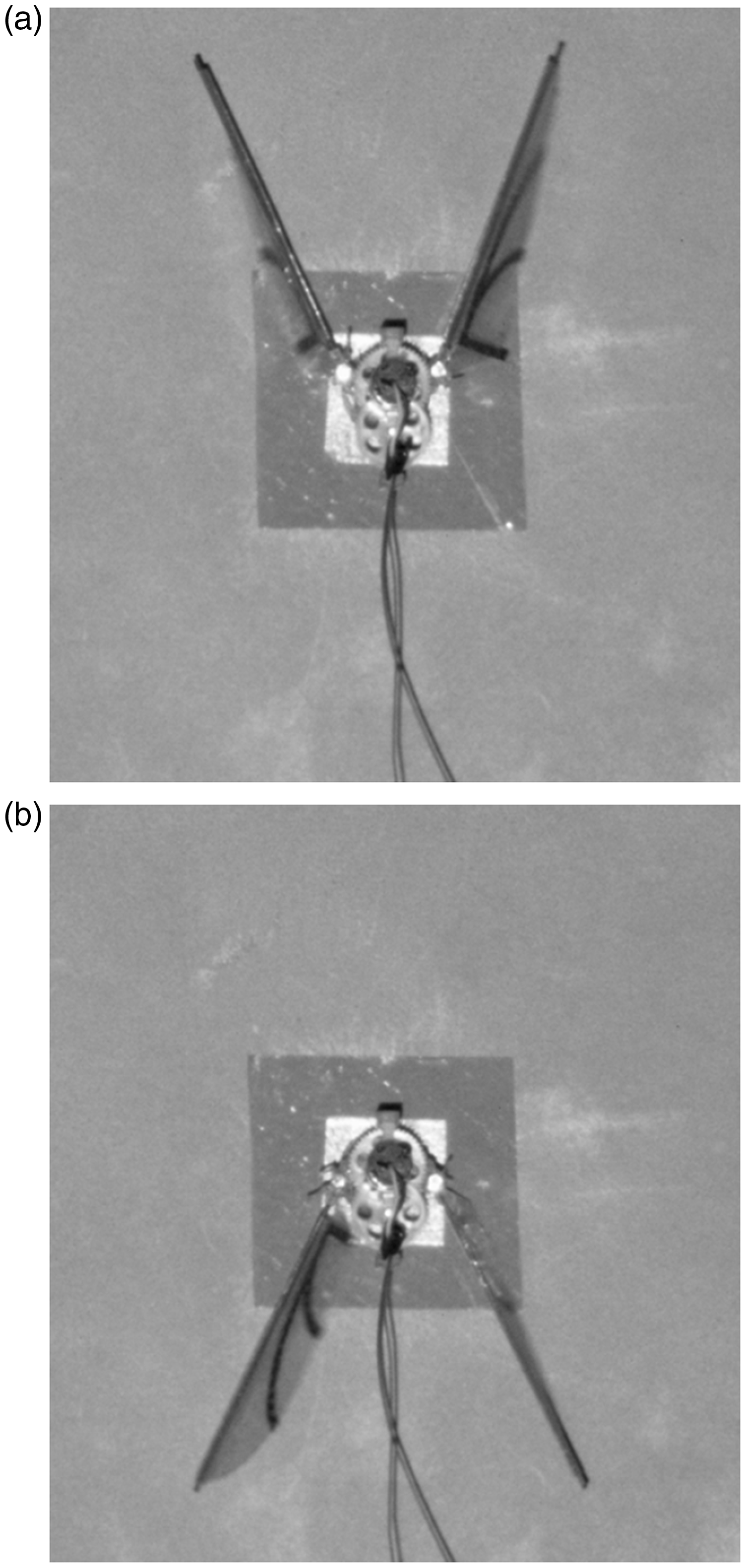
Operation of the prototype at 3 V. (a) Fore stroke; (b) Down stroke.
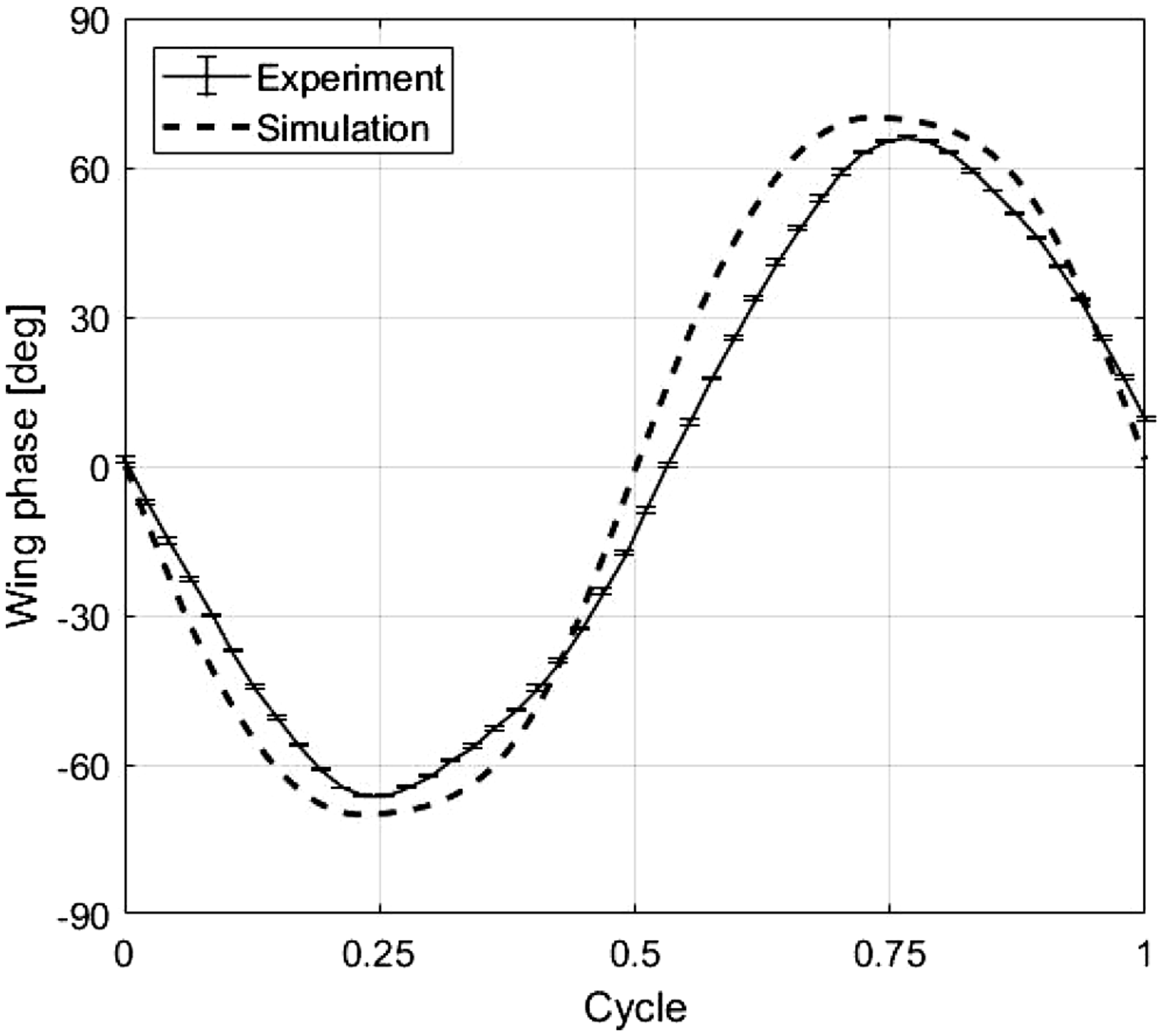
Comparison between the high-speed camera result and the simulation.
Figure 9 shows the measured thrust of the prototype in terms of the flapping frequency. A 6-axis load cell, ATI NANO17-E transducer 24 is used to measure the thrusts at 1 kHz of the sampling frequency. The thrust increases quadratically with respect to the flapping frequency, which corresponds well to the trend in the literature. 25 The present flapping mechanism generates 4.5 gf of thrust at a flapping frequency of 24 Hz with smaller wings than that in the earlier study. 25 Thus, the present flapping mechanism is expected to become more efficient when it is joined with wider wings and provided by a faster flapping speed.
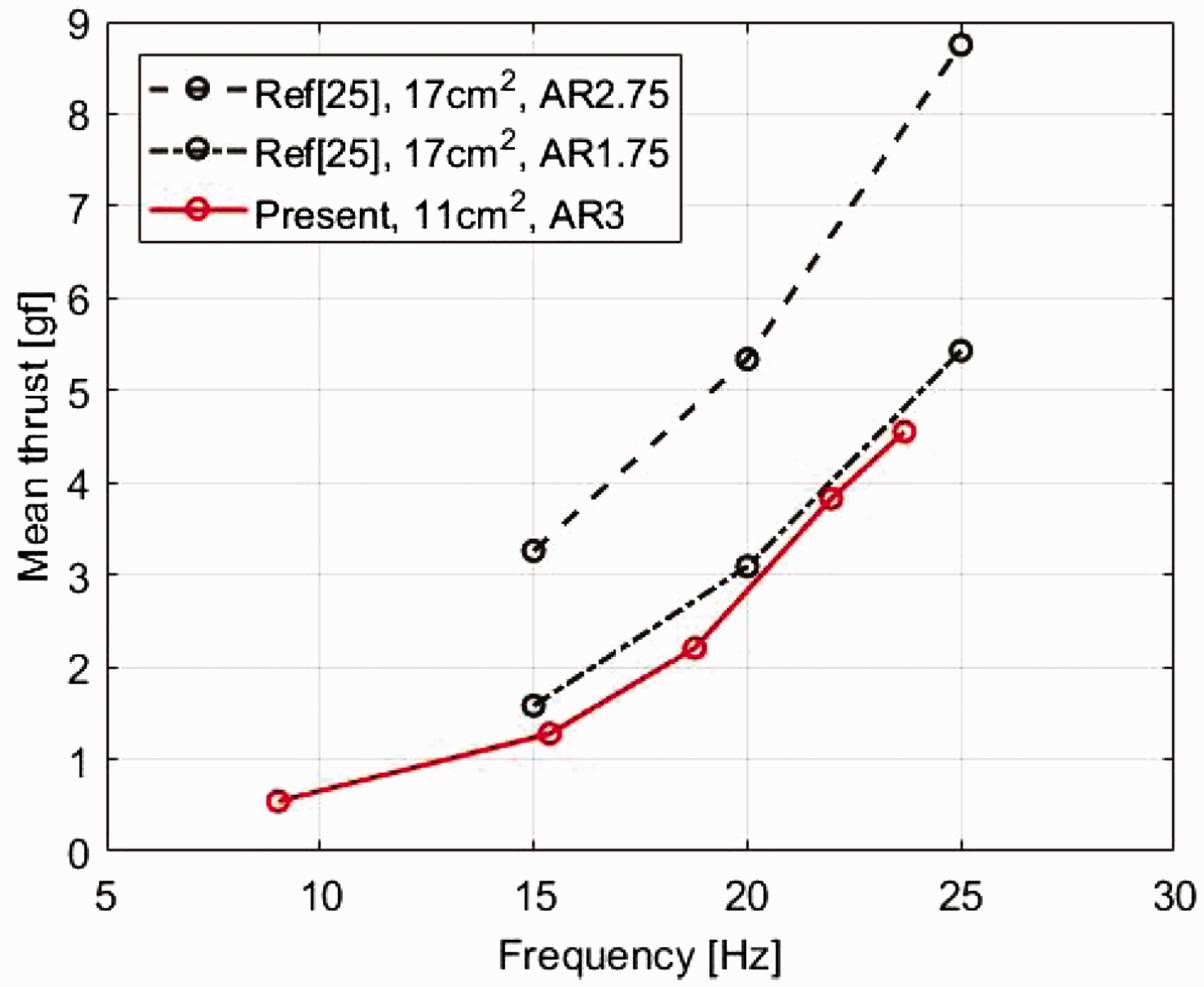
Flapping frequency result of the prototype.
Control mechanism design
Among FWMAVs, insect-mimicking tailless FWMAVs do not have a control plane. Hence, the overall assembly can be even smaller and lighter. To control the attitude of the vehicle without any control plane, an insect-mimicking tailless FWMAV will require special control equipment adjusting the flapping motion of the wings. Figure 10 shows the orientation and the control direction of the MAV in hovering condition. Thus, in many earlier studies,6–8,11–15,19,26,27 unique control methods of tailless FWMAVs were developed and experimental results were obtained. Owing to the unsteady aerodynamic characteristics of flapping wing, it has been difficult to obtain analytical estimations of the control moment. As such, the estimation of the control moment depends on experimental measurements. Moreover, FWMAVs have strict weight limits for several reasons. These circumstances restrict the list of motors which can be used in the control mechanism.

The orientation and control moments of the FWMAV.
Three types of existing control mechanisms are analyzed and compared. The first control mechanism is a joint control mechanism, as shown in Figure 11, which attempts to shift the flapping axis and also change the flapping angle amplitude by manipulating certain components in its flapping mechanism. Second, the stroke plane change (SPC) method rotates the stroke plane. The stroke plane is changed by rotating the leading edge trajectory by tilting the flapping slot, as shown in Figure 12. The final method is trailing edge control (TEC). In this mechanism, root spar displacement enforces the wing membrane to be deformed, which induces a thrust or drag change, as shown in Figure 13. Through unequal twist between both sides of the wing, TEC can produce thrust or drag imbalance which generates the control moment.

Flapping area change when manipulating flapping mechanism joint. (a) Rolling motion; (b) Yawing motion; (c) Pitching motion.

Stroke plane change (SPC) mechanism configuration and its operation. 19 (a) SPC control method and its operation; (b)Details of the SPC mechanism.

TEC control method and its operation. 26 (a) Trailing edge movement and wing twisting; (b) TEC operation in the rolling direction; (c) TEC operation in the pitching direction.
Design requirements
Before initiating the mechanism design, four design requirements are selected by analyzing numerous control mechanisms suggested in previous studies. First, the control mechanism must be modularized. Certain control mechanisms have connectivity between the flapping mechanism and the control mechanism. This causes these methods to be limited to a specific flapping mechanism. For example, the joint control mechanism, as shown in Figure 11, should be connected to certain components in a flapping mechanism. As modularized control mechanisms can be developed independently and combined freely with a flapping mechanism, modularization can be one of the main criteria in the design of the control mechanism. SPC and TEC can be modularized and generate the control moment without changing the flapping motion. Another design criterion is induced by the inherent weight limit of the FWMAV. The weight limit is set to 7 g according to the second design requirement. The third design criterion is set to satisfy the position holding capability. Instead of a weight reduction, the DC motor has difficulty in maintaining the desired position, even a neutral position. Therefore, a position holding capability will be needed for DC motor if it is used for control mechanism. The last design requirement is possibly the smallest cross-coupling among the control moments. In an experimental test of a TEC mechanism in an earlier study, 11 the critical cross-coupling property of the TEC becomes significant as the pitching and yawing moments are combined with the undesired rolling moment.
Rolling and pitching motion descriptions of the TEC control mechanism
Through a comparative analysis of several FWMAV control methods, the control method using the TEC is selected and designed to satisfy the four design requirements, i.e., modularization, the weight limit, maintaining capabilities in a neutral position, and minimized cross-coupling. The design is progressed with minimum consideration of the present flapping mechanism. According to a survey of actuators available in the market, the stepping motor is found to be too heavy for the present case. Accordingly, a DC motor whose weight is 0.7 g is finally selected. Gear boxes reduce the required torque for the DC motor to rotate the components of the control mechanism. In order to minimize the cross-coupling property, the present TEC control mechanism is designed to implement rolling and pitching motion without yawing motion, as there are more alternatives for yawing control.
In Figure 14, a simplified schematic of the TEC control mechanism is depicted. The pitch driving components are attached to the main shaft. Because the main shaft rotates in the rolling direction with the pitch driving components, independent driving in the pitching direction is possible without the use a complicated two-degree-of-freedom hinge. The rolling motion is described in Figure 14(b). A main motor and gears which increase the torque and rotate the main shaft in the rolling direction are used. Accordingly, the trailing edges of both wings are twisted or stretched, causing a thrust imbalance in both wings and generating control moment toward the rolling direction. Meanwhile, a neutral position can be maintained using the self-weight and a high gear ratio. The center of gravity of the driving components which are attached to the main shaft is located below the main shaft. Therefore, the self-weight improves hovering stability of the vehicle in the rolling direction, as stated in the literature. 27 In addition, the gears engaged with the main motor increase the main shaft driving torque and decrease the torque required to return to the neutral position.

Schematic of the present TEC mechanism. (a) Configuration of the TEC mechanism; (b) Operation in the rolling direction; (c) Operation in the pitching direction.
Secondly, the pitching motion is described in Figure 14(c). The pitch driving components include a gear box and a root spar connector. The gearbox, where a worm gear and small pinion are engaged, is expected to maintain the weight balance of the entire vehicle. When the pitch motor drives the worm gear and pinion, the root spar connector will rotate in the pitching direction. Accordingly, the trailing edges of both wings will be bent toward the pitching input direction, which causes a thrust imbalance between the forward and backward directions. As a result, the bent trailing edge generates control moment in the pitching direction. In addition, a neutral position or an input position can be maintained during pitching motion because the torque to return to the neutral position by the self-weight is reduced in the gearbox.
Fabrication of prototypes for a performance experiment
The design of the driving test prototype is conducted using CAD software, and it is fabricated as shown in Figure 15. As described before, because the TEC control mechanism is modularized, it can be assembled with any type of flapping mechanism. In the trailing edge experiment, a flapping mechanism using the 6-bar link mechanism, detailed in the literature of Jeon et al., 12 is assembled with the TEC control mechanism. For assembly with the flapping mechanism, the driving test prototype requires connecting components. A CAD drawing of the modified design with connecting components is presented in Figure 16(a). In addition, Figure 16(b) and (c) describes the rolling and pitching motions, respectively. The root spars are restrained up to the required angles to prevent failure of the wing membrane.

Drawing and the prototype for driving test. (a) CAD drawing; (b) Driving test prototype.

Drawings of the TEC control mechanism with the connecting components. (a) Isotropic view; (b) Rolling motion description; (c) Pitching motion description.
A relevant prototype is fabricated in order to evaluate the driving performance. The prototype weighs 4.1 gf and the driving experiment is conducted for both rolling and pitching motion. Trailing edge change experiments are performed for each motion using the assembled prototype. As shown in Figure 16, trailing edge twisting or stretching for the rolling input and bending for the pitch input are demonstrated. A ground test using a 6-axis load cell, ATI NANO17-E transducer 24 is then conducted to verify whether sufficient control moment is generated. The control moments were measured with 1 kHz of the sampling frequency, then, filtered by the low pass filter with 300 Hz of cut-off frequency. The periodically averaged control moments measured under about 16 Hz of flapping frequency which induces about 4.2 g of thrust are plotted in Figure 17. The rolling and pitching moments during one flapping cycle are presented in Figure 18(a) and (b), respectively. The solid lines are acquired by averaging five periods of data and the error bars indicate the maximum and minimum values during the 5 periods. The periods are divided using 16 Hz of the flapping frequency. The average control moments are found to be 11–17 gf⋅cm at the full control input. Considering that the control moments are approximately 10 gf⋅cm according to the literatures,13,14,19 the feasibility of the control mechanism is well demonstrated.

Front view of the assembled prototype according to the control inputs. (a) Neutral position; (b) Rolling motion; (c) Pitching motion.

Control moment history during one flapping cycle. (a) Rolling moment; (b) Pitching moment.
The moments induced by the control coupling effect are about 30% of the main control moments. For example, when the root spars are tilted to the pitching up position, the induced rolling moment will be 1.5 gf⋅cm which is 36% of the pitch moment 4.17 gf⋅cm. Similarly, during the rolling right test, the induced pitching moment is 20% of the main rolling moment. Thus, when comparing to the other designs6,11,12,14 which have at most 50% of the control coupling effect, the control coupling effect of the present mechanism is solvable via an adequate control algorithm.
Conclusion
In this paper, novel designs of flapping and control mechanisms for an FWMAV are suggested and experimentally tested. With regard to the flapping mechanism, string is used to reduce the weight and power consumption. The design parameters are optimized by applying the GA-PS method. An FWMAV prototype fabricated by the optimized design parameters is experimentally evaluated to assess the feasibility of the mechanism. Using a high-speed camera, the flapping frequency of the proposed flapping mechanism is measured and found to be 24 Hz at an input voltage of 4 V. Additionally, in a load cell measurement, approximately 4.5 gf of thrust is generated, though this may be improved through changes in the wing design.
A trailing edge control mechanism is also designed for the pitching and rolling moments. The present control mechanism is modularized so that it can be assembled with different flapping mechanisms. A prototype which combines the flapping and control mechanisms is fabricated. The wing membrane is deflected properly by the proposed control mechanism. In addition, the measured control moment is found to be approximately 10 gf⋅cm with full control input. Thus, the feasibility of the present control mechanism is suitably verified in the experiments conducted here.
Because the flapping and control mechanism were designed and tested separately, tasks are left to combine them and conduct flight test. Locking method between the flapping and control mechanism should be provided. Wireless communication for control input and simple control logic will be given to the vehicle. Also, research on a structural analysis, weight reduction, and wing design optimization will be carried out to build a new FWMAV. Stress in the string or components of the control mechanism will be estimated in a flexible multibody dynamic analysis to secure longevity of the vehicle. Reducing the weight and optimizing the design will improve the maneuverability, efficiency, and flight time, enabling the vehicle to conduct such missions as scouting, rescue, and reconnaissance.
Footnotes
Acknowledgements
The authors acknowledge the aid provided by Professor Chongam Kim and his graduate students at Seoul National University.
Declaration of conflicting interests
The author(s) declared no potential conflicts of interest with respect to the research, authorship, and/or publication of this article.
Funding
The author(s) disclosed receipt of the following financial support for the research, authorship and/or publication of this article: This research was supported by a grant to the Bio-Mimetic Robot Research Center Funded by the Defense Acquisition Program Administration and by the Agency for Defense Development (UD130070ID).