
Abstract
This paper presents the experimental studies of the efficiency of open and ducted contra-rotating propeller systems operating in the low Reynolds number range. Eight off-the-shelf propellers were selected with a diameter in the range from 139 mm to 377 mm and seven ducts were built with the duct length of 0.28–0.53 the propeller diameter. Static and wind tunnel experiments were conducted. The maximum increase in the static thrust coefficient and power loading for the ducted contra-rotating propeller systems over the open systems was found to be 25% and 50%, respectively. This performance improvement for the medium size ducted systems is smaller than that observed in previous studies for ducts longer than the 0.8 propeller diameter but greater than for ducts shorter than the 0.15 propeller diameter. The thrust coefficient decreases with an advance ratio increase. The power loading of both open and ducted systems drops dramatically after reaching maxima.
Introduction
The efficiency of hover-capable Unmanned Aerial Vehicles (UAVs) can be improved by using aircraft configurations with ducted (shrouded) propellers (rotors). For the evaluation of propeller performance, the main parameters are thrust and power coefficients and power loading. In order to achieve their desired values, geometric shapes of the inner and outer surfaces of a duct have to be properly designed.
In its basic form, a section of the cylindrical duct resembles a cambered airfoil. There are three geometric features yielding performance gains of ducted propellers: properly designed inlet accelerating the flow towards the rotor, a clearance between blade and duct improving tip flow, and diverging diffuser section restraining the flow from contraction. Ducts can be described by the following variables: inner diameter, total length, inlet radius, tip-to-blade clearance, diffuser angle, and length. They can be non-dimensionalized by the inner diameter of a duct or the propeller diameter.
Pereira and Chopra 1 performed parametric studies of effects of shroud geometry on hover performance of a single rotor. They tested 10 ducted rotors of the diameter of 160 mm with rectangular untwisted blades. The length of the shroud was 0.8–0.85 of the rotor diameter. A definitive trend in a behavior of thrust was seen with a blade clearance. The ducted rotor with the clearance of 1–0.1% of the rotor diameter shows the thrust coefficient increase by up to 65% as compared to the isolated rotor at a relatively high values of the power coefficient. Note that the highest increase values correspond to a relatively low input power. When the value of clearance increases, both thrust and power performance degrade. These effects have been observed for the blade pitch angle of 10° and greater. In contrast, for a smaller blade pitch, the thrust and power performance of the ducted rotor is declined compared to the open rotor. Nonetheless, the tip clearance demonstrates the greatest impact on rotor performance.
A larger inlet radius would cause a larger skin friction drag, while a sharper inlet is prone to a flow separation and a pressure drag. Data presented in the study 1 show that the thrust coefficient increases with an increase of the inlet lip radius at the same power input. Taylor 2 observed a significant decrease of the thrust coefficient when the inlet radius is near zero. The thrust coefficient increases with the radius increase until approximately 6% and remains unchanged at larger values. Note that the case of a very large radius can be treated as representative of a fan-in-wing design configuration.
According to Black et al., 3 increasing the diffuser angle from 8° to 14° increases static thrust by up to 15%. However, very large diffuser angle worsens ducted single propeller performance due to the flow separation caused by the backpressure and skin friction drag. 4 Both the duct and the propeller thrusts were measured in the experimental program. 4 Obtained results showed that for a fixed duct length, increase of the diffuser angle from 0° to 20° did not have a strong effect on the duct thrust fraction. The optimal value of the diffuser included angle of 10° was obtained by Pereira and Chopra 1 with the diffuser length was 50% of the duct throat diameter.
From the design prospective, the coaxial contra-rotating propeller system has benefits of a smaller footprint compared to two single rotors placed side by sided. Therefore, more studies are needed for better understanding propulsive effectiveness of contra-rotating propeller systems.
In the study by Dyer, 5 ducted propulsion consisting of two contra-rotating propellers of the diameter of 228 mm was investigated. The total length of the device was of 1.44 the propeller diameter. For the value of the blade tip clearance of 0.225%, the maximum thrust coefficient is higher by about 18% then for 0.45%. Results show that the optimal inlet radius has to be maintained greater than 6%, thus confirming results of studies single-propeller ducted systems.1,2
Thipyopas et al.6,7 investigated the ducted contra-rotating rotor system of 470 mm diameter featuring a very short diffuser resulting in the total duct length of 0.17 the rotor diameter. The experimental results show that the best efficiency of the open propulsion system can be achieved when both rotors use the same pitch angle and the lower rotor rotates a little faster. The duct has a strong positive effect on total thrust and power efficiency for higher pitch angles in the range of 15°–20°, while for the case of a single open rotor, the best efficiency in terms of power loading was achieved at the pitch angle of 10°. These conclusions are in agreement with results published in the previous study on the single-rotor ducted system. 1 They are explained by flow acceleration in the inlet and, thus, a larger blade pitch angle needed to obtain the same angle of attack on the blade as in an open rotor. Lastly, the power loading of the shrouded configuration was found only 3% greater than that of the free coaxial rotors.
The contra-rotating rotor system of 188 mm diameter with a relatively long shroud of the length of 1.17 rotor diameter was investigated by Huo et al. 8 The static pressure distribution on the inner surface of the duct was measured and found to be lower in front of the upstream rotor in comparison with the open rotor. A suction peak on the leading edge of the duct contributes in a significant way into the increase in thrust of the ducted system. Additionally, mass flow rate was determined based on the total and static pressure measurements. A mass flow increase in a ducted coaxial system explains enhancement in its overall thrust efficiency by up to 80% in comparison with the open rotors.
Using ducted propellers in multicopter design implies a minimum shroud length for a given propeller diameter. Majority of studies of effects of shroud design parameters on the propulsive effectiveness were conducted for relatively long ducts (0.8–1.4 the propeller diameter1–5,8). Both single propeller and two coaxial propeller systems were investigated, whereas studies on contra-rotating systems with very short ducts (of 0.17 the propeller diameter6,7) showed only minor improvements in the propulsion performance. For better understanding, effects of duct size on propulsive effectiveness of the contra-rotating propellers, the experimental studies of medium size ducted contra-rotating propeller systems are needed.
Investigations of the systems with the duct length of 0.3–0.5 propeller diameter will be conducted in the present work. Thrust and power of several open and ducted models utilizing off-the-shelf propellers will be characterized and thoroughly analyzed under hover conditions and with the presence of the incoming airflow.
Experimental methods and models
An open contra-rotating propeller-motor propulsion system shown in Figure 1 consists of a pair of propellers mounted on concentric shafts. The propeller 1 is attached to one end of the cross-shaft and the other end is fixed to the propeller case of motor 1. Motors are brushless outrunners.

Open contra-rotating propeller system.
The propellers connected to corresponding motors turn in opposite directions. The two motors are driven independently by two Electrical Speed Controllers (ESCs).
Quantities recorded in experiments are a thrust force, an input electric power, and revolutions per minute (RPM). For the analysis of the ducted and open contra-rotating systems, a non-dimensional thrust coefficient is employed

The advance ratio is defined as
Determining a propulsion efficiency of system with contra-rotating propellers in terms of figure of merit is difficult because the shaft torque measurement is a challenging task, which was not done in the present study. The present experimental setup allows recording of voltage,

The power loading will be used as a measure of efficiency of contra-rotating propeller system
It provides a performance comparison basis of different propulsions in terms of absolute values of minimum power,
For the hover conditions, the Reynolds numbers for propellers were determined using the reference speed and the chord length at the 75% blade station. Obtained values were in the low Reynolds number range of 1.6–9.9·104.
Based on the aerodynamic analysis of airflow around ducted propellers,10,11 the main parameters affecting the performance of ducted propulsion are identified in the literature1–3,5–7 as:
Duct airfoil shape, especially on the inner surface. Height of the duct, H, influencing flow separation in the outlet section. Leading edge radius, R, affecting a suction force. Duct-propeller tip clearance,
As illustrated in Figure 2, experiments on the models were conducted in the University of Arizona Subsonic Wind Tunnel (Figure 2) with a 0.91 m by 1.22 m test section.
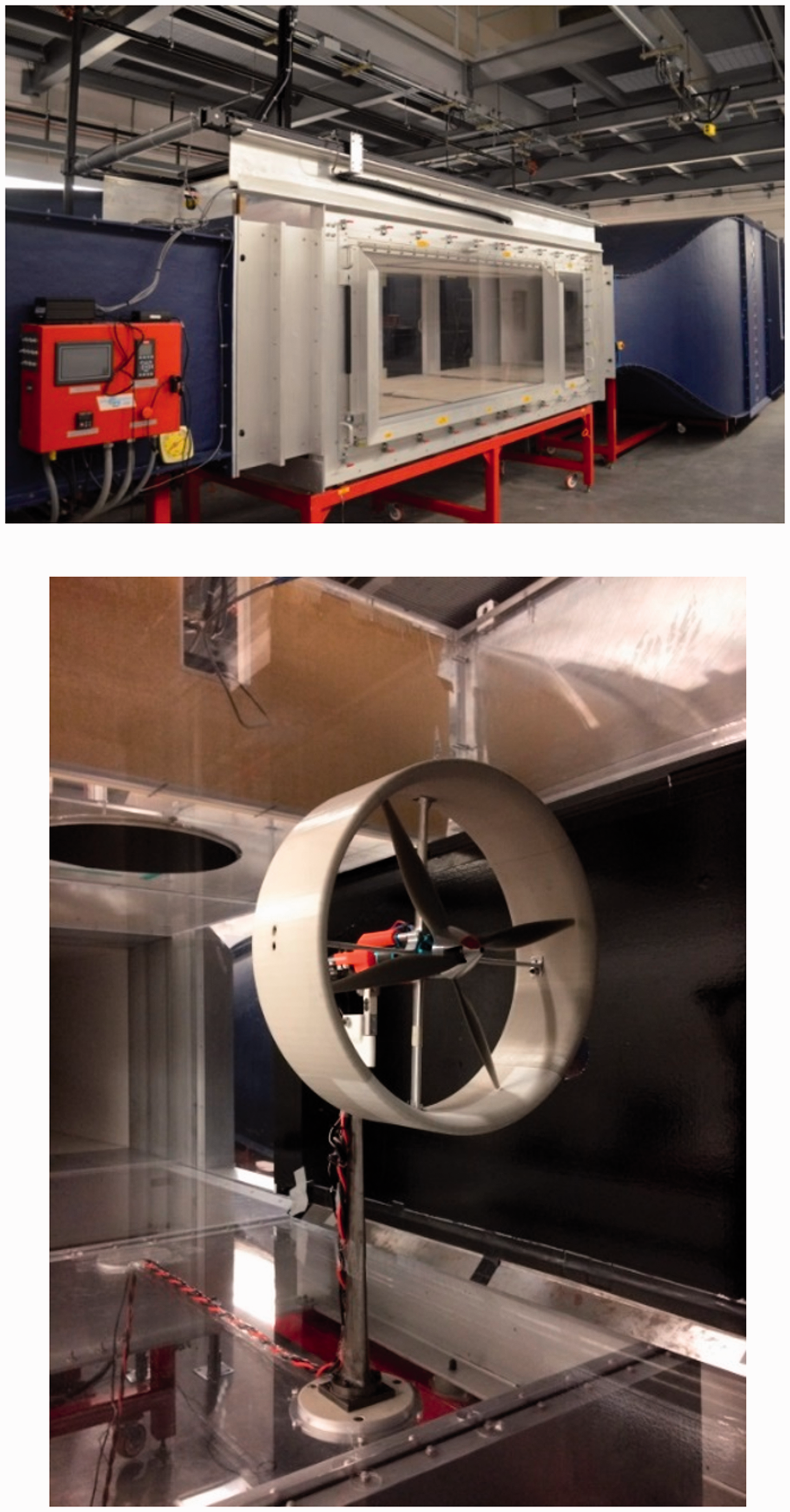
Subsonic wind tunnel (upper) and model installed in test section (lower).
The experimental setup inside the wind tunnel is shown in Figure 3. The propulsion is powered by DC power supply HY3050EX. The instantaneous thrust force, input voltage, and current to ESC are recorded by Dynamometer 1580 with a sampling rate of 50 Hz. The propeller angular velocity is measured by Tachometer DT-2100. At each test point, 10 datasets have been recorded, the averaged results are utilized in the analysis below.

Experimental setup inside wind tunnel.
Calibration of the Dynamometer 1580 was performed before each test series with the help of a calibration fixture supplied by the manufacturer. According to the device specifications, 12 the expected accuracy of measurements is 1% of the full-scale range for the thrust. The electric power was calculated based on voltage and current recordings (see equation (4)). The accuracy of the electric power measurements is approximately 1.5%.
Characteristics of investigated propulsion systems are presented in Table 1 and illustrated in Figure 4. Eight off-the-shelf propellers were utilized in the study. Geometric parameters of an assembly of contra-rotating propellers are given in Table 2 and follow notations in Figure 1.
Parameters of propellers and motors.

APC: Advanced Precision Composites; GF: Glass Fiber.
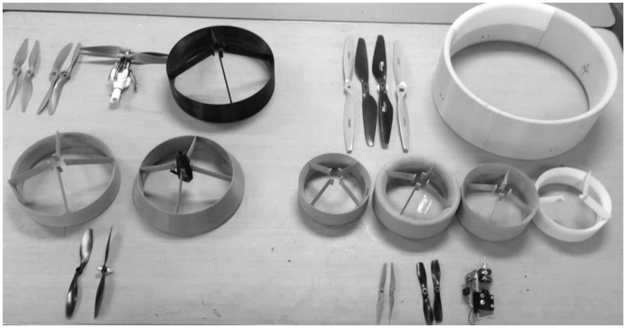
Propellers and ducts.
Geometric parameters of contra-rotating systems.

Configuration of a generic duct cross-section is shown in Figure 5. Geometric parameters of ducts are given in Tables 3 and 4.
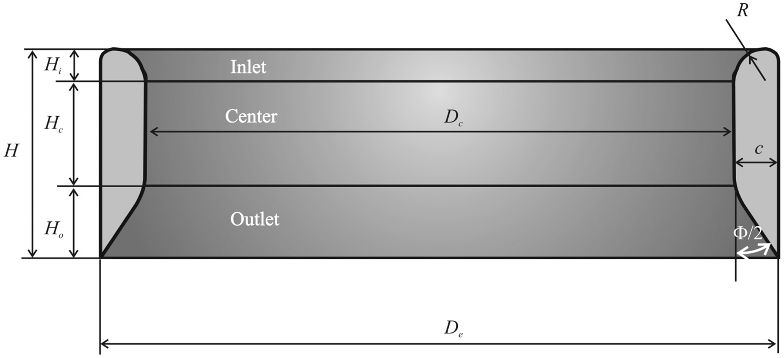
Geometry of a duct.
Dimensions of ducts.

Non-dimensional parameters of ducts.

Results and discussion
Static and wind tunnel experiments were conducted on the open and ducted contra-rotating propeller models listed in Tables 1 to 4. Obtained data are presented in the form of graphs displaying variations of the thrust coefficient and power loading with RPM. Furthermore, thrust coefficients and power loadings of the ducted systems are expressed relative to the open systems in order to uncover effects of duct size, propeller blade pitch, and tip clearance on the performance of ducted systems.
RPM characteristics of contra-rotating systems
In the present study, the two contra-rotating motors are independently controlled by two ESCs. Therefore, even the two ESCs have the same PWM control input, the RPM of the motors differ if the upper and lower propellers worked under different torques. Ducts accelerate the airflow due to the contraction of the inlet section, and therefore differently affect the RPM of the upper and lower propellers.
RPM were recorded for open and ducted propulsions as a function of mechanical input power, Pw. Figure 6 illustrates results obtained for open and ducted models 55 and 84. Results of measurements showed that RPM of open upper and lower propellers nearly coincide. With a duct installed, the RPM of both upper and lower propellers increase and the RPM of the upper propeller has a larger increase than the lower one. This effect cannot be explained by aerodynamic interaction only since the total mechanical power on the shaft is a sum of input powers of two motors that may not be the same. Overall, the RPM difference between upper and lower propellers is smaller than 5% under different working conditions. Hence, only the RPM of the upper propeller was recorded in the following experiments as a nominal RPM of the propulsion system.
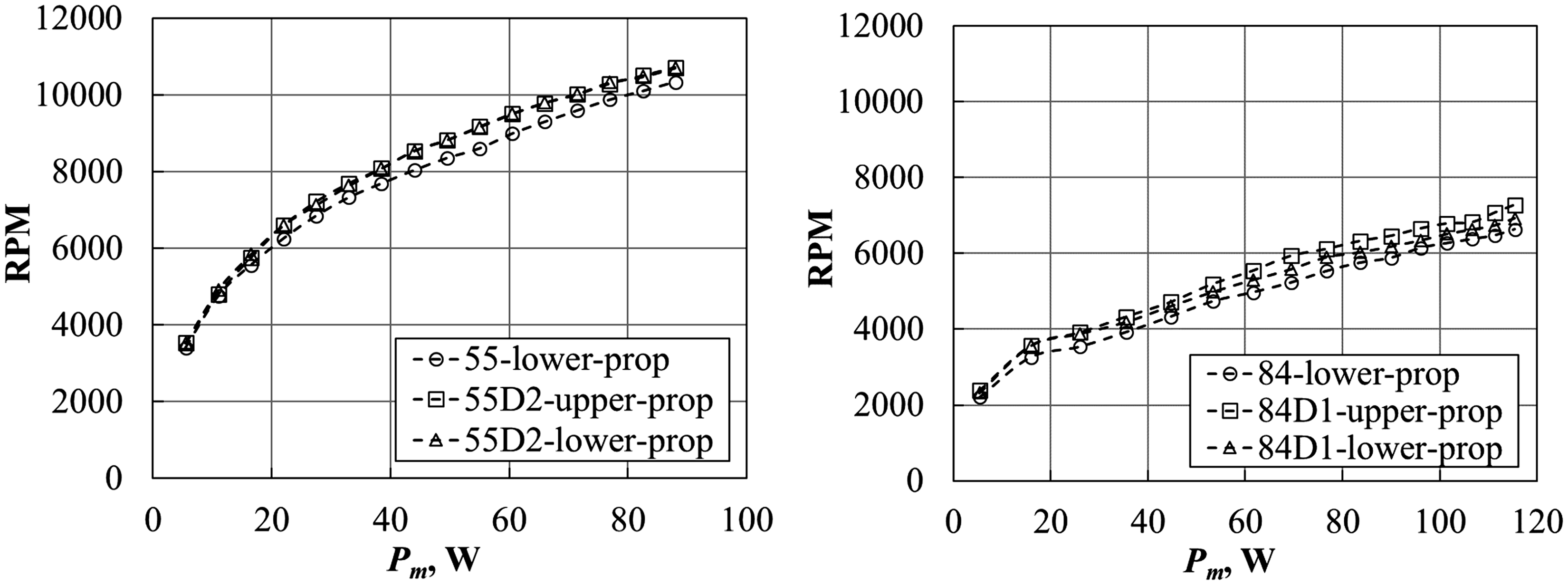
Variation of RPM with power in ducted and open propulsions.
For larger size models, 105, 107, 108, and 1510 values of RPM for open and ducted systems were close with maximum differences not exceeding 1–2%.
Open contra-rotating propeller systems in hover
Experimental data for open (unducted) contra-rotating propeller systems provide a baseline for comparisons with ducted systems. Variations of the thrust coefficient,
The thrust coefficient,
From Figure 7(a), it was observed that the thrust coefficients in the open system 55 are almost twice higher than in 54, while the chord of the propeller in the system 55 is almost two times larger. Thus, the higher thrust coefficient found in the system 55 is associated with its higher solidity. However, this thrust increase requires more power: 8.5 W and 19 W for the propellers 54 and 55, and a higher power loading of systems 54 than 55 at 6000 r/min: 0.086 and 0.066, respectively. For the RPM higher than 7500, the power loading values are identical.

Static performance of open models 54 and 55: (a) thrust coefficeint and (b) power loading.
Interesting results were obtained for the open systems 84 and 86. While the propeller 84 has 36% lower pitch, it has approximately 34% larger chord as compared to the propeller 86. Such a combination of opposite effects resulted in closeness of static performance parameters as seen in Figure 8.
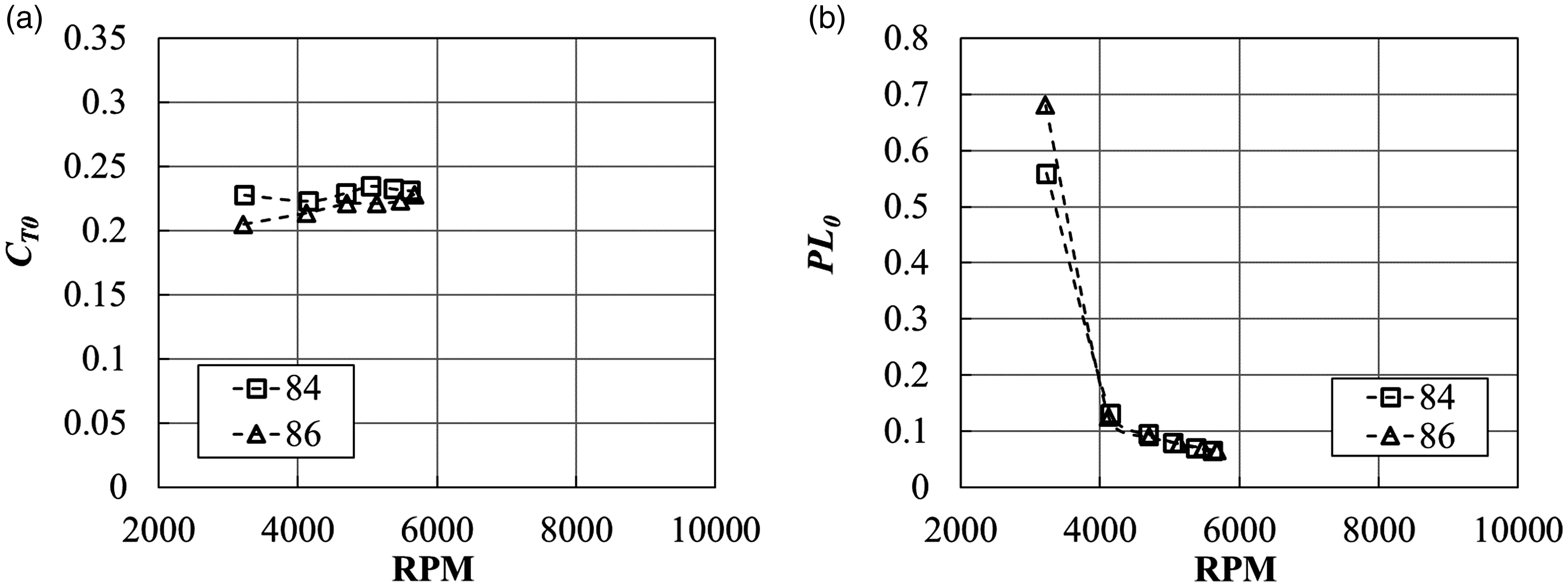
Static performance of open models 84 and 86: (a) thrust coefficeint and (b) power loading.
The effects of the blade pitch angle are clearly seen in the open models 105, 107, and 108. They have the same solidity, but different pitch angles. As seen in Figure 9, the thrust coefficient increases with a pitch angle increase from the propeller 105 to 107 and to 108. The opposite trend is observed in the power loading.

Static performance of open models 105, 107, and 108: (a) thrust coefficeint and (b) power loading.
Finally, a static performance of the open system 1510 is presented in Figure 10. The values of

Static performance of open model 1510: (a) thrust coefficeint and (b) power loading.
Results for coefficients
Thrust coefficients and power loadings for static case.
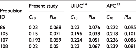
The effect of contra-rotating propellers aerodynamic interactions is evident in lower
Ducted contra-rotating propellers in hover
Static performance parameters of ducted and open contra-rotating systems are presented in Figures 11 to 15 and in Table 6. Plots are provided for best performing systems and in order to illustrate variations in thrust coefficients and power loadings. Table 6 contains ratios of ducted to open system parameters
The thrust coefficient and power loading graphs for both open and ducted models 54 are presented in Figure 11. As seen, both

Static performance of ducted and open systems 54: (a) thrust coefficeint and (b) power loading.
For the ducted model 54D1 at 6000 r/min, parameters
Both systems 54 and 55 perform better with the duct D1 than with D2. While both D1 and D2 have the same blade tip clearance of 0.72%, the duct D1 has almost two times larger inlet radius than D2 (Table 4), which explains its better static performance.
Comparing datasets presented in Table 6, it is clear that systems 54 outperformed 55 with both ducts D1 and D2. This result can be explained only by the smaller blade pitch angle of 14.7° in the systems 54 compared to 16° in 55.
Static performance parameters of the open 86 and ducted 86D2 models are presented in Figure 12. For the model 86D2 at 6000 r/min,

Static performance of ducted 86D2 and open 86 models: (a) thrust coefficeint and (b) power loading.
It can be seen from Table 6 that the ducted model 84D1 shows very little improvements over the open model 84. A relatively high efficiency of the 84D2 over the 86D1 can be explained by larger blade pitch angle and almost twice smaller blade tip clearance (Table 4).
Parameters of static performance of the systems 108 are illustrated in Figures 13 and 14. The results for the 108 and 108D1 closely align with each other. Significant performance improvements are noticed in the ducted model 108D2. The duct D2 has 50% smaller blade tip clearance, which is the main factor enhancing the system performance in this case.
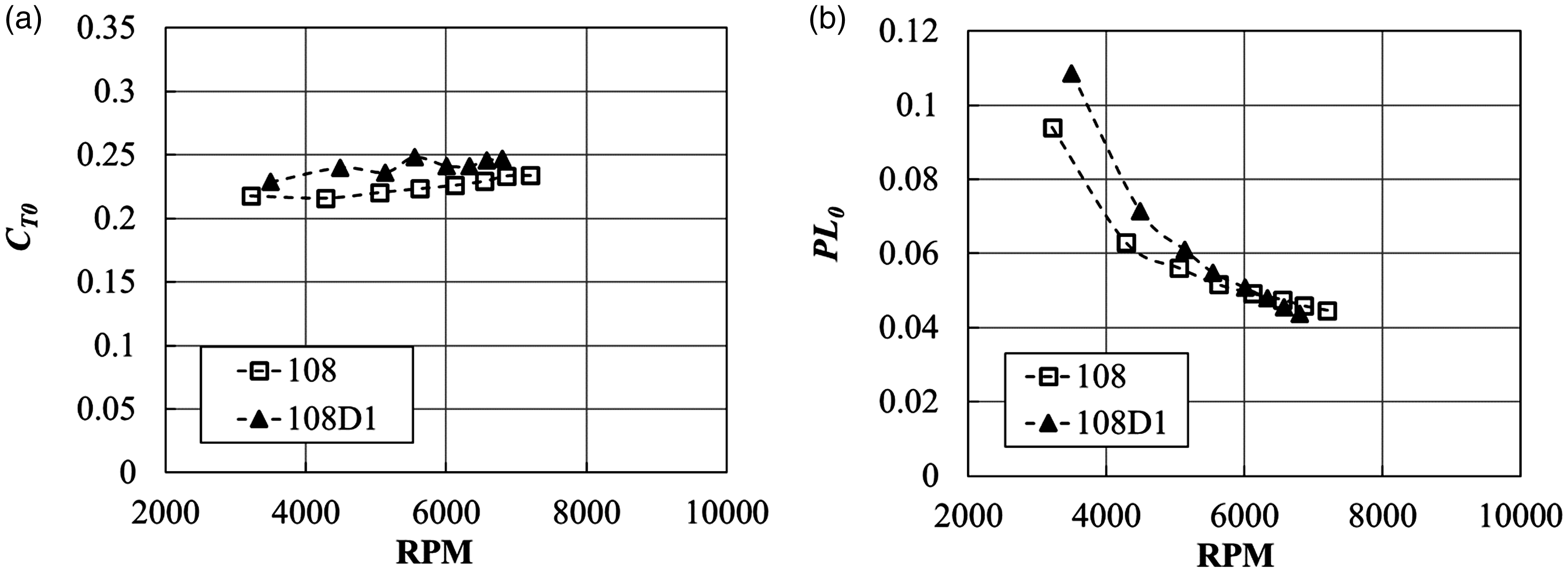
Static performance of ducted 108D1 and open 108 models: (a) thrust coefficeint and (b) power loading.

Static performance of ducted 108D2 and open 108 models: (a) thrust coefficeint and (b) power loading.
Results in Table 6 show that thrust and power performance of ducted models 105D1 and 105D2 decline compared to the open system 105. This system is characterized by the smallest blade pitch angle of 9.1°. Similar effects were observed in Pereira and Chopra 1 for single-propeller ducted systems with the blade pitch angle smaller than 10°.
With a pitch angle increase to 12.8° and 14.4° in ducted systems 107 and 108, respectively, thrust coefficient and power loading ratios gradually increase. Even though the relative thrust coefficient remains less than unity for the duct 107D1, the maximal positive effects are achieved in the model 108D2 with the blade pitch angle of 14.4° and they are comparable with the results for 54D2 having approximately the same blade pitch angle of 14.7°. Overall, static performance effects observed in ducted models 105, 107, 108 are consistent with previous investigations1,6 in two aspects: static performance is improved with smaller blade clearance and with blade pitch angle greater than 10°.
The 1510D2 model shows only minor benefits over the open model 1510, as seen in Figure 15. Using results provided in Table 6, a propulsion performance of the model 1510D2 was compared against 107D2. While these propulsive systems are of different diameter and length, their blade pitch angles and blade tip clearances are about the same (Tables 1 and 4). As a result, gains in the thrust coefficients and power loadings for these models are close.

Static performance of ducted and open propulsion 1510: (a) thrust coefficeint and (b) power loading.
Thrust coefficient and power loading ratios at 6000 r/min.

Effects of freestream
Performance of a propeller propulsion changes significantly with the incoming flow. Wind tunnel experiments were conducted over a range of advance ratios for discrete freestream velocity values of 5, 10, and 15 m/s. The best static performers, open 54 and ducted 54D1 systems, were tested in the wind tunnel with the propeller axis aligned with the direction of the airflow. Variations of thrust coefficient and power loading with the advance ratio,

Thrust coefficient of open 54 and ducted 54D1 models as function of advance ratio.

Power loading of open 54 and ducted 54D1 models as function of advance ratio.
The thrust coefficient gradually decreases with an advance ratio increase at a steeper slope in the ducted system graph. Note that at J=0 (zero freestream velocity) and at 6000 r/min,
Looking at the power loading in Figure 17, a different trend is observed. There is an improvement in efficiency at low advance ratios before the power loading function reaches its maximum. At 5 m/s, the open model peak corresponds to J = 0.29, but the ducted model maximum is attained at lower advance ratio of J = 0.2. It is worth noting that in the previous study, 11 the efficiency of a single open propeller shows a peak in the 0.25–0.65 range.
The power loading of both open and ducted systems drops dramatically after reaching maxima, but the performance of a ducted system deteriorates faster due to a drag force produced by the freestream flow on the outer surface of the duct. The ducted system reaches the windmill state (zero thrust and power loading) at much lower
Summary
Using ducted propellers in multicopter design implies a minimum shroud length for a given propeller diameter. In order to determine the effect of the duct length on the contra-rotating propeller system performance, a testing program was devised to measure a thrust, an RPM, and an electric power. Eight off-the-shelf propellers with diameters ranging from 139 mm to 377 mm were selected and seven ducts with the duct length of 0.28–0.53 the propeller diameter were built and tested in hover and with incoming flow. The maximum increase in the static thrust coefficient and power loading for the ducted system over open systems was found to be 25% and 50%, respectively. This performance improvement for the medium size ducted systems is smaller than that observed in previous studies for ducts longer than the 0.8 propeller diameter but greater than in ducts shorter than the 0.15 propeller diameter. The blade pitch angle varied from 9.1° to 16°, and power loading and thrust coefficient gains were observed for the blade pitch angle values of 10°–16°. However, model 107D1 showed poor thrust performance. As in the previous studies, decreasing the blade tip clearance provided performance gains and larger inlet tip radius demonstrated a better static performance of ducted systems. The performance of the ducted contra-rotating system changes significantly with the incoming flow. The thrust coefficient decreases with an advance ratio increase at a higher rate in ducted systems. The power loading of both open and ducted systems drops dramatically after reaching maxima. The performance of a ducted system deteriorates faster due to a drag force produced by the freestream flow on the outer surface of the duct.
Footnotes
Declaration of conflicting interests
The author(s) declared no potential conflicts of interest with respect to the research, authorship, and/or publication of this article.
Funding
The author(s) received no financial support for the research, authorship, and/or publication of this article.