
Abstract
A wire-driven parallel robot with eight wires (WDPR-8) acting as the suspension system for an aircraft model in a low-speed wind tunnel is introduced in this paper. A kinematics model for WDPR-8 is established here. A theoretical basis is also provided, through which movement control of the model is achieved by changing the wire length. A model motion control subsystem, a monocular vision measurement subsystem for the model position, and a data acquisition subsystem were also developed for WDPR-8. A prototype of WDPR-8 was built and mounted in a low-speed wind tunnel with an open test section. A six-component strain-gauge balance was installed inside the test model to acquire aerodynamic parameters. The aerodynamic coefficients of the static test show reasonable agreement with reference results. The difference between the test result of WDPR-8 and the results from reference is smaller in the positive angle of attack than the negative angle of attack, and the total difference between WDPR-8 and other facilities is under 10%. Pitch dynamic tests with different amplitudes and frequencies were used to verify the aerodynamic hysteresis phenomena. The research indicates it is successful that the solution of measuring aerodynamic parameters with strain-gauge balance set into the standard dynamic model suspended by WDPR. It demonstrates that WDPR-8 is effective and feasible as a model suspension system in a low-speed wind tunnel. Furthermore, test results without interference correction in accordance with the reference data proves that the interference of Wire-Driven support system to flow field during wind tunnel tests is negligible. Finally, WDPR suspension system introduced in this paper will remarkably improve the efficiency and accuracy in wind tunnel test.
Introduction
WIND tunnel tests are crucial in the development of new flight vehicles. The model mount is a device that holds a test model in a required position, or controls the position and attitude of the model in the test section of the wind tunnel. Model mounts, including a sting or strut, are made of high strength steel with significant dimensions to withstand all the aerodynamic loads exerted on the test model. Although they are widely used, the accuracy of the experimental results will be affected by aerodynamic interference or vibration owing to conventional mount systems. The traditional rigid support mode, due to the support frame, causes distortion of the flow around the model, which makes the model test results different from the aerodynamic characteristics of the real aircraft.1–3
To improve the data accuracy of the wind tunnel test, the development of new support system is one of the urgent problems to be solved. Significant efforts, such as data correction procedures4,5 and magnetic suspension and balance system (MSBS), 6 are developed to minimize or eliminate the shortcomings of model mounts. A wire-driven parallel robot (WDPR) suspension system is a type of parallel robots, the obvious advantage of which is the avoidance of the above drawback when it is used as a model suspension system in a wind tunnel. Furthermore, the particular property of wires provides WDPR several other advantages, including larger workspaces, higher payload-to-weight ratio and lower manufacturing costs rather than rigid-link robots, and both static and dynamic tests can be conducted with the same suspension system. 7
In the last several decades, a few studies have been carried out to study both the theory and implementation of suspension systems using WDPR for wind tunnel tests. Bennett et al. 8 tried to extract stability derivatives from flight test data obtained from aeroelastically scaled flutter models tested in a wind tunnel on a cable-mount system. Griffin 9 described a model support and attitude control system for wind tunnel test. In the patent, the model is fixed by four aerodynamically designed vanes to two parallel wheel-like supports. By rotating the wheels, the attitude of the model can be changed during testing without changing the aerovane lengths. The active suspension system for the wind tunnel tests project SACSO (Suspension active pour essais en soufflerie), one representative example of WDPR, is sponsored by Office National d’Etudes et Recherches Aerospatials (ONERA) and has been utilized in wind tunnel tests in the design of novel fighters.10,11 John et al. 12 demonstrated of a Wire Suspension System for Dynamic Wind Tunnel Testing. A wire driven parallel suspension system with eight wires (WDPSS-8) was developed as a WDPR application for the wind tunnel at Xiamen University, 13 with which the aerodynamic parameters were computed from the signals of eight tension sensors on the wires with that system. Lambert et al. 14 investigated a platform supported by the wire driven traverse (WDT) utilizing eight thin wires and demonstrated its capabilities on an axisymmetric bluff body in a low speed wind tunnel. The WDT realized high-frequency harmonic motions using a wheel that was directly connected to a servo motor and accurately monitored force responses with in-line load cells. Wang et al.15,16 investigated the Hybrid pose/tension control based on stiffness optimization of cable-driven parallel mechanism in wind tunnel test and the feasibility of large-scale model suspended by cable-driven parallel robot in hypersonic wind tunnel test. Wang et al. 17 proposed the back-stepping sliding mode robust control for a wire-driven parallel robot based on a nonlinear disturbance observer and proved the feasibility and validity of the proposed control scheme through both simulation and experimental results. Wang 18 analyzed the workspace of cable-driven parallel mechanism for wind tunnel test. A X-51A-like model is suspended and the simulation result showed that the system is stable enough to meet the fundamental static wind tunnel test. Chen et al. 19 from Jimei University proposed the force sensitivity of a 6-DOF cable-driven parallel robot. Park et al. 20 developed a cable suspension and balance system. Two novel methodologies to improve the suspension system performance, one for more accurate motion control and the other for improved load measurement, were suggested. Wu et al. 21 posed a three Degree-of-Freedom (DOF) mechanism for virtual flight test in the wind tunnel. The dynamic simulation verified the ability of the suggested support mechanism to meet the requirements of the wind tunnel virtual flight test support system.
This paper details an experimental investigation performed in a low-speed wind tunnel to assess whether it is feasible to measure static and dynamic aerodynamic forces using a built-in strain-gauge balance while the model is suspended by a WDPR. Innovative work in this article includes the redesign of the suspension wire scheme, the measurement of the model pose through monocular vision, the pose control policy with parallel robot technology, the acquisition of aerodynamic parameters by an inbuilt six component strain-gauge balance in the model, and the brand-new prototype. The remainder of this paper is structured as follows. Section II provides a detailed description of the supporting mechanism of the wire-driven parallel robot with eight wires (WDPR-8), followed by the development of the suspension scheme and the kinematic relationship analysis of WDPR-8. Section III presents the important hardware system of WDPR-8, including a model motion control subsystem, an aerodynamic measurement subsystem, and an attitude acquisition subsystem. In section IV, the standard dynamic model (SDM) and test facility are presented. The prototype was mounted on an open straight-flow low-speed wind tunnel in the China Aerodynamics Research and Development Center (CARDC), and the test results are analyzed and compared with the results of other facilities, see section V. Finally, the main results of this work are summarized and some conclusions are discussed in section VI.
Structure of the WDPR-8 prototype
WDPR-8, a type of WDPR with eight wires, was designed in this study. A test model was suspended using WDPR-8 in wind tunnel tests. Figure 1 shows a photo of the WDPR-8 prototype constructed in the laboratory.

WDPR-8 prototype.
The brace frame of the prototype was constructed using aluminum alloy (no. 6060). There are eight driving components mounted on the eight horizontal bars of the frame, each of which consists of a ball screw assembly, a servomotor, a driving wire, and a universal pulley. The slider on each ball screw assembly moves back and forth, driven by corresponding motors. Owing to its excellent tensile strength (E = 43.9 GPa), wires with a diameter of 0.5 mm constructed from Kevlar fiber were chosen for the driving wires of the prototype. One end of a wire is attached to a joint point on the aircraft model, and the other end is connected to a slider through the universal pulley. The SDM model was suspended in the middle of the prototype using eight driving wires.
WDPR supporting mechanism
A simplified structure of Figure 1 is illustrated in Figure 2, where Figure 2(a) displays the wire joint points on the frame. Figure 2(b) shows a partial enlarged view of the SDM model, in which joint points on the model are more clear. A global coordinate system Ogxgygzg and a body coordinate system Obxbybzb were set up as shown in Figure 2. In the latter, the origin is set at the barycenter P of the model. The Obxb axis coincides with the axis of the fuselage and is directed toward the nose of the model. The Obyb axis points toward the right wing tip. Finally, the Obzb axis is determined in accordance with the right-hand rule and is perpendicular to the other two axes.

Schematic prototype of WDPR-8: (a) structural sketch of WDPR-8 and (b) wire joint points on SDM.
The slider on each ball screw is driven by servomotors which move accurately in a straight line along each ball screw and are used to stretch out and draw back the wires, thus allowing the wire length to be changed. The motors are simultaneously controlled by a programmable multi-axis controller (PMAC).
The attach points
Structural parameters of WDPR-8; dimensions in mm.

The wires are exerted pre-tension, and their tension degrees are adjusted using the ball screws and servomotors. A change in the length of wires due to the movement of sliders along the screws can accomplish movement control of the model to meet the test requirements. With WDPR-8, 6-DOF motion of an aircraft model is easily achieved, which includes three translational degrees and three rotational degrees. The workspace of WDPR-8 is basically determined by the position of Bi and P i in Table 1. 22
Suspension scheme of WDPR-8
To measure the aerodynamic force using WDPR, we developed a model scheme with a built-in strain-gauge balance in the suspension system, as shown in Figure 3, under the comprehensive consideration of the workspace and stiffness of WDPR-8. 23

SDM scheme with a built-in balance in suspension: (a) suspension scheme of model with strain-gauge balance and (b) suspension scheme of the strain-gauge balance. 1 – Driving wire; 2 – Front cone; 3 – Six component strain-gauge balance; 4 – Parallel Sleeve; 5 – Rear cone; 6 – Supporting rod; 7 – Horizontal bar; 8 – Fuselage; 9 – Small short strut; 10 – Nose.
A parallel sleeve is mounted directly on the tail-end of the balance through its rear cone. The supporting rod is fixed to the rear cone. The aircraft model is fixed to the leading-end of the balance through its front cone.
There are four small short struts jutting out from four holes on the fuselage of the SDM. These are installed symmetrically on the parallel sleeve. The wires are tied at the strut tips. The struts and wires are not in touch with the fuselage at all times, as is shown in Figure 3(b). Furthermore, sufficient clearances were maintained between the parallel sleeve and the fuselage of the model and between the sleeve and the balance so that the aerodynamic force could be measured without interference using the balance.
The extension lines of four struts converge along radial to the point P on the model, which is also the barycenter of the model. The front four wires were fastened to the four struts and the rear four wires were tied to the two ends of the horizontal bar. The model pose was controlled by changing the wire lengths according to the requirements of the tests.
Kinematic model of WDPR-8
During motion control of an aircraft model, the attitude of the model is adjusted by adjusting the length of the wires. A kinematic model for WDPR-8 is set up here to determine the interrelationship between the lengths of the wires and the attitude of the model.
The kinematic relationship of WDPR-8 is illustrated in Figure 4. For the convenience of expression, the aircraft model is simplified as a bold cross. Its long axis coincides with the main axis of the model fuselage, and the lateral axis is parallel to the direction of the model wingspan.

Illustration of the kinematic relationship in WDPR-8.
The vector

where

where
Let

where

The unit vector along the wire is
The relationship between the pose or velocity of the aircraft model and the wire length Li (i = 1, 2,…, 8) is determined according to equations (1)–(4). The change in the three rotational degrees and the three transitional degrees of the model can be transformed to a variation in the supporting wire length. Thus, single or coupled DOF movement of the aircraft model can be achieved with the suspension of WDPR-8 in a wind tunnel for tests.
Hardware system of WDPR-8
WDPR-8 is made up of a hardware system and a software system. Their structures and interrelationships of WDPR-8 are shown in Figure 5.
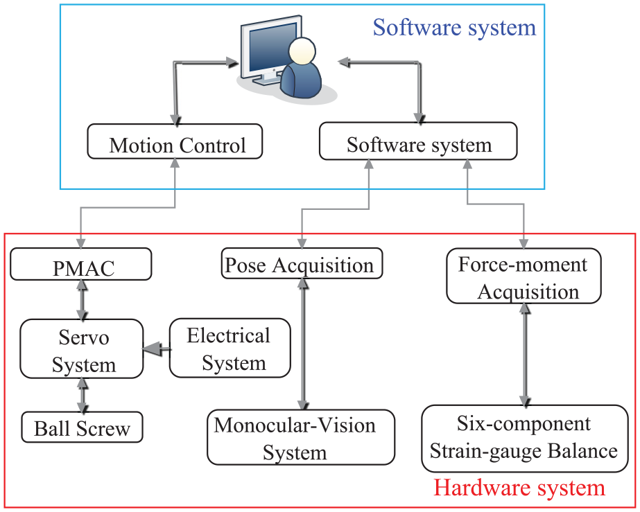
System structure of WDPR-8.
The software system is finished in a host computer. The programs of the software system were all self-developed, some of which have been approved by China’s SIPO issuing software copyright certificates. The hardware system is composed of three subsystems which include the model motion control subsystem, the aerodynamic force measurement subsystem, and the monocular vision subsystem (MVS) for the model pose.
Model motion control subsystem
The model motion control subsystem of WDPR-8 was developed based on a turbo PMAC. The model motion control interface is shown in Figure 6.

Interface of the model motion control subsystem.
The interface consists of eight modules including control parameters settings module, PMAC state and motor enabling buttons, a real-time parameter list of the model pose, the state of the motor, security status, instantaneous order of the PMAC, internal parameters of the PMAC, and a parameter list of the motors and the wire tension.
It is convenient to manipulate the aircraft model in accordance with the planned movement using the control command from the motion control interface. For instance, the model can oscillate in single DOF (such as pitch, yaw, or roll) and coupled DOF and even perform simultaneous motion in 6-DOF. Meanwhile, the attitude of the model, running state of the motors, tension of the wires, and the status of the system are all monitored in real time.
Aerodynamic force acquisition subsystem
Six-component strain-gauge balances are widely utilized in wind tunnels to acquire aerodynamic forces and torques. The six-component strain-gauge balance (G0201B) adopted in the test was from CARDC.
As shown in Figure 3, together with the six-component balance and parallel sleeves, the aircraft model translates or rotates synchronously in 6-DOF, driven by the servomotors on WDPR in a wind tunnel. The aerodynamic force and aerodynamic moment are also captured by the strain-gauge balance and restored synchronously.
Model attitude monocular vision subsystem (MVS)
As opposed to a traditional rigid support system, the model is suspended in a WDPR, which moves in 6-DOF in wind tunnel tests. In the progress, the attitude and position of the model vary and cannot be measured using methods that are similar to those used in rigid support systems. As a result, an MVS was applied to capture the pose of the model.
The MVS in Figure 7 is composed of a CMOS camera, IEEE 1394 data capture card with a pair of six-conductor alpha connectors, infrared source, infrared filter, calibration board, HALCON, and six fluorescent marked points on the model.

Monocular vision subsystem (MVS) of WDPR-8.
When building an MVS, it is necessary to determine the datum coordinate system of the camera by capturing a picture of the calibration plate. The initial pose of the model should be calibrated before tests. In general, the pose of the model must first be set to zero. That is, the three attitude angles of the model should all be adjusted to zero, and its barycenter should be located at the center of the test section of the wind tunnel. Combining with MVS, the attitude of the model can be controlled by the model motion control subsystem based on PMAC. In addition, there is an one-button returning function in the subsystem, with which the pose of the model is able to return its initial state based on closed-loop control. Thus, the attitude will be set to zero or a predetermined value through one-button returning technology before each test.
Fluorescent marked points on the upper surface of the model represent the pose of the model. The position of the points, the so called fluorescent marked points, on the model must be arranged in a special form in order to determine the attitude of the model. Any three points should not be on the same line. When the model moves on a given motion planning, images of six characteristic points were captured and processed to solve the attitude of the aircraft model relative to the datum coordinate system, which is recorded and stored in real time.
The workspace of WDPR-8 shown in Figure 7 can attain pitch, roll, and yaw angles of ±50°, ±20°, and ±35°, respectively, and translation distances of ±200, ±200, and ±300 mm in the Ogxg, Ogyg, and Ogzg directions, respectively. The workspace parameters are obtained through experiments with WDPR-8 prototype in Figure 1, which is the same size as the test equipment installed in the wind tunnel in Figure 9. The test model was controlled to translate or rotate to the extreme positions and the corresponding workspace parameters are recorded. The static accuracy values of the angle and position are 0.05° and 0.1 mm, respectively. The MVS accuracy are 0.02° and 0.05 mm, respectively, better than the accuracy of the robot. A model pitch oscillation test can be conducted using the suspension system with amplitudes between 0° and 20° and frequencies between 0 and 4.0 Hz.
Model and equipment
Test model
The SDM, first introduced by National Aeronautical Establishment, CANADA (NAE),24,25 was adopted to investigate the feasibility of WDPR-8 in a low-speed wind tunnel. The SDM here is 0.36 times the size of the original model of NAE. The maximum length, the fuselage diameter, and the wingspan of the model were 378, 54, and 244 mm, as shown in Figure 8 and Table 2 respectively.

Standard dynamic model (SDM).
Parameters of SDM.

Wind tunnel and equipment installation
The test was carried out in an open low-speed wind tunnel of CARDC. The length of the test section was 1075 mm. The cross sections of the inlet and outlet were octagonal with side lengths of 346 and 396 mm, respectively. The height of the section’s center line was 1994 mm. The airflow speed could be adjusted from 0 to 51 m/s. Pressure loss coefficient from the inlet of the wind tunnel to the test section is 0.005 and the mean turbulence intensity is 0.2%.
A picture of WDPR-8 in a wind tunnel is shown in Figure 9. Except for the model and the driving wire with a diameter of 0.5 mm, the bracing frame and other acquisition apparatus are outside the airflow. Therefore, the interference of the suspension system on the flow field is negligible.

Installation of WDPR-8 in a wind tunnel.
Tests and data analysis
A prototype of WDPR-8 was installed and served as the model support in a low-speed wind tunnel to test its feasibility in wind tunnel tests. Both static and dynamic tests were conducted, and the results were compared with the data from rigid support systems. On this basis, the pitch oscillation of the SDM in wind tunnel tests was also recorded at different frequencies and amplitudes.
Static test
The aim of the static test is to check the validity of WDPR-8 as an aircraft model support in wind tunnel tests. According to the experimental data from the strain-gauge balance, the lift force coefficient CL, drag force coefficient CD, and pitching-moment coefficient Cm were calculated and compared with the experimental results from Cyran
1
(Air flow condition is Ma = 0.6, Re = 1.6 × 10⁶) and the test data from AVIC-627 (Aviation Industry Corporation of China, Aerodynamics Research Institute, AVIC-627) (the wind speed is 72 m/s, mean turbulence intensity of the wind tunnel is 0.16%, Re = 1.23 × 10⁶). Static tests were conducted with the model fixed at certain angles of attack under the following test conditions: Velocity: 17 m/s Angle of attack: −10° to 40° Angle of side slip: 0° Reynolds number: 0.988 × 10⁶
During the wind tunnel tests, the model was adjusted to a specific angle of attack and was then fixed in sequence.
Figure 10 shows the lift force coefficient (CL) curve of the model from this paper compared with the reference data from two other research institutes. Further observation of Figure 10 indicates that CL increases as the angle of attack increases from −10° to 18°. The stall angle occurs at around 18°. When the angle of attack is higher than 20°, CL increases again. This is similar to the aerodynamic characteristics of the SDM, of which the CL has twice speed raising owing to the strake wing. Furthermore, it can be found that the test results are in agreement with those from the test facilities from AEDC and AVIC-627 at angles of attack ranging from 0° to 20°, and differences appear beyond this range. Quantitative analysis to Figure 10 displays that the error between the test result of WDPR-8 and the results from other two facilities is smaller in the positive angle of attack than the negative angle of attack, and the total difference between WDPR-8 and other facilities is under 10%. This phenomenon can be attributed to the particular characteristics of each experimental setup used, such as differences in the suspension system, characteristics of the wind tunnel, the effects of model blockage, interference on the flow field around the model caused by model support systems, and the use of various airspeeds.

Lift force coefficient of SDM in static tests.
Despite the difference in wind tunnel test facilities and test conditions, the test results here show reasonable agreement with the reference data, which proves the validity of suspension using WDPR-8 in a wind tunnel.
The variation in the drag force coefficient (CD) at different angles of attack and the comparison with the tests results from other facilities are shown in Figure 11. It can be observed that CD decreases from −10° to 0° and increases above 0°. Furthermore, it increases more significantly with an increase in the angle of attack, which coincides with the aerodynamic characteristics of the SDM.

Drag force coefficient of SDM in a static test.
The comparison between the test results of the pitching-moment coefficient (Cm) from WDPR-8 and data from references is shown in Figure 12. Similar to the situation with CL, the experimental data from different sources are relatively consistent in the scope of a small angle of attack, but there is evident disparity among the data at a high angle of attack. This is mainly due to the different interference of support systems and the change of support system to the shape of model. Other reasons may include the different wind tunnels and the test conditions, such as the Reynolds number, the effects of model blockage, and different airspeeds.

Pitching-moment coefficient of SDM from a static test.
All of the above test results were obtained without support interference correction for WDPR-8 in the wind tunnel; this shows that the effect of the interference in WDPR-8 on the wind tunnel test was significantly weak. The disturbance on the flow field can therefore be ignored. As a consequence, the feasibility of using WDPR-8 as an aircraft model support was demonstrated in a low-speed wind tunnel. The solution that the aerodynamic parameters are measured by six-component strain-gauge balance set in the SDM suspended for wind tunnel static test is successful.
Pitching oscillation test
Data processing for dynamic tests
The pitching oscillation test was performed for the SDM using WDPR-8. Data processing is very important for such dynamic tests.
In order to obtain pure aerodynamic force and moment signals, the inertia and acceleration of the model must be deducted by subtracting the wind-off signal from the wind-on signal while the model oscillates under the same motion conditions. Accordingly, the wind-off signal and wind-on signal must align in phase angle. However, it is difficult to align the signals using the traditional hardware trigger method. The Fourier transform and inverse Fourier transform approach are utilized in the paper to solve this problem.
Consider a set of typical signals y(t) from a channel of the balance. y(t) = f(t − t0) can be transformed from the time domain to the frequency domain using a fast Fourier transform (FFT) in ORIGIN:

Similarly, the signal y(t) = f(t + t0) can also be transformed using an FFT:

From equations (5) and (6), it is not difficult to figure out that the phase angle ωt0 can be calculated from the Fourier transforms of the signals from the balance mounted in the model oscillating sinusoidally. If the signals in the frequency domain are multiplied by
If the wind-on and wind-off signals are pre-treated with the above approach, they will align exactly in phase angle. The data of the dynamic tests in this section are all pre-treated using the above phase-shift before further data processing.
Test results and analysis
In the tests, the SDM moved in a large amplitude pitching oscillation according to the following equation:

where α is the angle of attack, α0 is the mean angle of oscillation, A is the amplitude of oscillation, and f is the frequency of oscillation. In the oscillatory motion, the yaw angle and roll angle of the model were kept at 0°.
The reduced frequency of the pitching oscillatory motion is defined as

where ω = 2πf is the circular frequency, cA is the mean aerodynamic chord, and V∞ is the airflow velocity in the wind tunnel tests.
Figure 13 shows the experimental results of the SDM moving in a pitching oscillatory motion with A = 5°, f = 0.78 Hz, and κ = 0.027. In the figure, f = 0 Hz represents the static test result. It can be seen that the aerodynamic coefficient curves of CL and Cm are different from their behavior in a static test and that there is a hysteresis effect. This is because the aerodynamic force acting on the model differs as its angle of attack rises or declines near the same value. However, the general trend of the CL and Cm curves in Figure 13 is the same as that in the static tests. Each small hysteresis curve ring surrounds a piece of the CL or Cm curve.

Dynamic test with A = 5° and f = 0.78 Hz: (a) comparison of CL in static and dynamic tests and (b) comparison of Cm in static and dynamic tests.
The curves of CL and Cm in Figure 14 were obtained for basically the same test condition as for Figure 13. The only difference is that Figure 14 includes one more result with the oscillation frequency of the model, that is, f = 1.18 Hz, κ = 0.04 for comparison with the results in Figure 13.

Test results for A = 5°, f = 0.78 Hz, and f = 1.18 Hz: (a) comparison of CL with different frequencies and (b) comparison of Cm with different frequencies.
From Figure 14(a), it can be observed that the CL of dynamic tests with f = 0.78 Hz and f = 1.18 Hz exhibited the same general trend as the CL of the static test. Overall, the oscillation frequency does not change the value of CL greatly, but different oscillation frequencies mainly have an influence on the area of the hysteresis loop of CL in Refs.26–28 The area enlarges when the frequency increases. The same phenomenon in Figure 14(a) also occurred in the pitching-moment coefficient (Cm) curve in Figure 14(b).
In Figure 15, there is the comparison of dynamic test results between WDPR-8 and AVIC-627. The hysteresis loops can be observed in the comparison of CL and Cm, and the hysteresis phenomenon of AVIC-627 is more obvious than that of WDPR-8, which is because of its larger amplitude and frequency. Generally, larger amplitude and frequency will lead to the increase of aerodynamic force and moment. Both the hysteresis loops of WDPR-8 and AVIC-627 show the similar trend. However, the hysteresis loop of AVIC-627 is larger because its angle of attack varies in a wider range.

Comparison of dynamic test, A = 20°, f = 0.78 Hz for WDPR-8, and A = 35°, f = 1 Hz for AVIC-627: (a) comparison of CL with AVIC-627 and (b) comparison of Cm with AVIC-627.
Above laws of the dynamic test results may be also found in other papers relative to the same test, 26 verifying the validity of applying WDPR-8 to dynamic tests in a low-speed wind tunnel.
Conclusions
The test technique described here provides the means to use an aircraft model suspension system with a wire-driven parallel robot (WDPR). A prototype of WDPR-8 together with several corresponding subsystems was built and installed in a low-speed wind tunnel to perform tests. Experimental data were collected using a six-component strain-gauge balance mounted in the SDM test model and a monocular camera. On the basis of the experimental results, the following conclusions can be drawn.
(1) The static test results coincide reasonably well with the results from previous studies, verifying the validity of using a WDPR as a model support in a low-speed wind tunnel and the successful use of a built-in six component balance for acquiring aerodynamic data. The hysteresis phenomenon and the results of dynamic tests validate the application of WDPR-8 to dynamic testing in a low-speed wind tunnel.
(2) Although the experimental data were treated without considering the disturbance of the WDPR-8 support on the flow field in the wind tunnel, the results are still mainly in accordance with the reference data. This proves that the influence of the WDPR-8 support on the wind tunnel tests is small; thus, the feasibility and availability of the WDPR-8 for both static and dynamic testing in low-speed wind tunnels.
(3) The function of the model suspension system is enhanced due to the adoption of parallel robot technology. As a result, the attitude angle, especial coupled angle, of the model will be easily changed according to the requirement of different tests, and the functions of several traditional systems may be realized conveniently by using one suspension system WDPR, particularly in dynamic tests. In consideration of the little interference to the flowfield surrounding the model, WDPR will remarkably improve the efficiency and accuracy in wind tunnel test.
Footnotes
Appendix
Acknowledgements
The authors are grateful to CARDC for providing experimental equipment and the researcher Haisheng Sun, Zhihong Shen, Yong Huang, and Weiguo Zhang of CARDC for their help on the data processing.
Handling Editor: Chenhui Liang
Declaration of conflicting interests
The author(s) declared no potential conflicts of interest with respect to the research, authorship, and/or publication of this article.
Funding
The author(s) disclosed receipt of the following financial support for the research, authorship, and/or publication of this article: This study was supported by the National Natural Science Foundation of China (No.11472234 and No.11072207) and Dr. Research Initiation Project of Chengyi College, Jimei University(NOJMT00117).