
Abstract
This paper presents the modeling, simulation, and control of a small-scale electric powered quadrotor tail-sitter vertical take-off and landing unmanned aerial vehicle. In the modeling part, a full attitude wind tunnel test is performed on the full-scale unmanned aerial vehicle to capture its aerodynamics over the flight envelope. To accurately capture the degradation of motor thrust and torque at the presence of the forward speed, a wind tunnel test on the motor and propeller is also carried out. The extensive wind tunnel tests, when combined with the unmanned aerial vehicle kinematics model, dynamics model and other practical constraints such as motor saturation and delay, lead to a complete flight simulator that can accurately reveal the actual aircraft dynamics as verified by actual flight experiments. Based on the developed model, a unified attitude controller and a stable transition controller are designed and verified. Both simulation and experiments show that the developed attitude controller can stabilize the unmanned aerial vehicle attitude over the entire flight envelope and the transition controller can successfully transit the unmanned aerial vehicle from vertical flight to level flight with negligible altitude dropping, a common and fundamental challenge for tail-sitter vertical take-off and landing aircrafts. Finally, when supplied with the designed controller, the tail-sitter unmanned aerial vehicle can achieve a wide flight speed envelope ranging from stationary hovering to fast level flight. This feature dramatically distinguishes our aircraft from conventional fixed-wing airplanes.
Keywords
Introduction
Vertical take-off and landing (VTOL) vehicles which possess VTOL ability, high maneuverability during vertical flight, and high efficiency in level flight have been investigated for a long time.1–3 Especially for the manned Vertical/Short Take-Off and Landing (V/STOL), many attempts have become mature and been serving for the military until now such as the Harrier GR7, V-22 Osprey, and F-35 Lightning. Small-scale electric powered VTOL unmanned aerial vehicles (UAVs), although in the infancy phase, also have attracted lots of recent attention. 4 They have great potential in many industrial applications: aerial photography, precise agriculture, intelligent surveying and monitoring, parcel delivery, border patrol, etc. Comparing with the widely used rotary-wing UAVs which have high maneuverability but low power efficiency and fixed-wing UAVs which have high cruise power efficiency but need extra facilities (e.g. runway, catapult) for take-off and landing, a VTOL UAV combining the advantages of rotary-wing vehicles and fixed-wing vehicles is a promising category of UAV which provides greater flexibility and capability (e.g. flight range, endurance, maneuverability) in many of the aforementioned applications.
There are mainly four categories of VTOL UAVs4,5: dual-system (e.g. a quadplane), tilt-rotor, tilt-wing, 6 and tail-sitter. 7 Among them, the tail-sitter VTOL aircrafts are perhaps the simplest implementation as they do not require extra transition actuators. These are useful in saving weight and reducing manufacturing complexity especially for lightweight UAVs with small size. Currently, lots of research have been done on the small-size tail-sitter VTOL UAV. Bapst et al. 8 proposed a dual rotor tail-sitter VTOL which consists of a flying wing with elevons and two rotors. An airflow model is proposed to estimate the reference airspeed (i.e. the combination of vehicle airspeed and propeller-induced airspeed) according to the actuator power consumption. A velocity controller is designed to calculate the desired attitude and thrust. Due to the poor measurement of the airspeed sensor on a large angle of attack, this controller is only verified with a small angle of attack. Verling et al. 9 proposed a full attitude controller. A half-model wind tunnel test is conducted to collect the aerodynamic force and moment at different angles of attack, elevon deflections, rotor speeds, and airspeeds. The collected data are used to approximate an aerodynamic model proposed by Anderson. 10 Then, the approximated aerodynamic model is used in the attitude controller. The outdoor experiment shows that this designed controller can work in both vertical flight and level flight. Ritz and D’Andrea 11 implemented a global controller for a dual rotor tail-sitter. A parameter learning scheme is used to estimate the pitching moment and aerodynamic lift and drag force of the vehicle. They use the on-board sensor to estimate the aerodynamics in real time. However, this may lead to inaccurate estimation if the vehicle enters a new flight regime. Similarly, Bronz et al. 12 developed a dual rotor tail-sitter named “cyclone". The aerodynamic model comes from Jameson 13 and Bronz and Drouin. 14 Since the accurate knowledge of airspeed and angle of attack is difficult to obtain. They apply the incremental nonlinear dynamic inversion controller to the vehicle, which needs no modeling of the vehicle dynamics and is very strong at disturbance rejection. The flight test shows that the developed vehicle can accomplish hovering flight and the transition flight between vertical flight and level flight.
According to Saeed, et al., 4 the tail-sitter can be roughly divided into two different categories: control surface transitioning tail-sitter (CSTT) and differential thrust transitioning tail-sitter (DTTT). The research work mentioned above belongs to CSTT. Comparing with a CSTT, a DTTT can easily produce a rapid and strong control moment during vertical flight, which makes it easy to control and has a better anti-wind performance during the vertical flight. Sinha et al. 15 proposed a DTTT UAV named “Quadshot”u The control system has two modes: hover mode and forward flight mode. The forward flight mode can accomplish the forward transition by smoothly varying the pitch command. No aerodynamics is considered in the control system. Oosedo et al. 16 developed an asterisk-type quadrotor tail-sitter VTOL UAV, which only use the differential thrust from the four rotors to produce the control force and moment. An optimal transition strategy 17 is developed to accomplish the forward transition (no backward transition results are reported). In the modeling process, the authors only consider the aerodynamics in the longitudinal direction. Theys et al. 18 developed a velocity controller based on the full envelop aerodynamics of the vehicle. The authors only use NACA 0012 airfoil aerodynamic coefficients to model the aircraft aerodynamics, which will lead to modeling error. The flight results show that the modeling error degrades the controller performance.
For a DTTT tail-sitter that is concerned in this paper (see Figure 1 and Table 1), it needs to perform transition maneuver between vertical and level flight by varying its attitude (i.e. pitch angle). During this process, the velocity and angle of attack change dramatically, leading to complicated aerodynamics on the vehicle. The wide flight envelope presents a great challenge in modeling and controlling of such UAVs. To handle this problem, building a complete model which can accurately predict the vehicleel motion is crucially important. Unlike most of the quadrotor modeling process, which is regarded as a simple rigid body with a motor collective thrust and differential torque that solely depend on the input pulse-width modulation (PWM) signal,19,20 the tail-sitter poses complicated aerodynamic forces and moments that dramatically deviate the UAV motion from a quadrotor. In addition, when the tail-sitter is in the level flight, a significant drop in propeller thrust and torque is encountered due to the presence of forward speed.
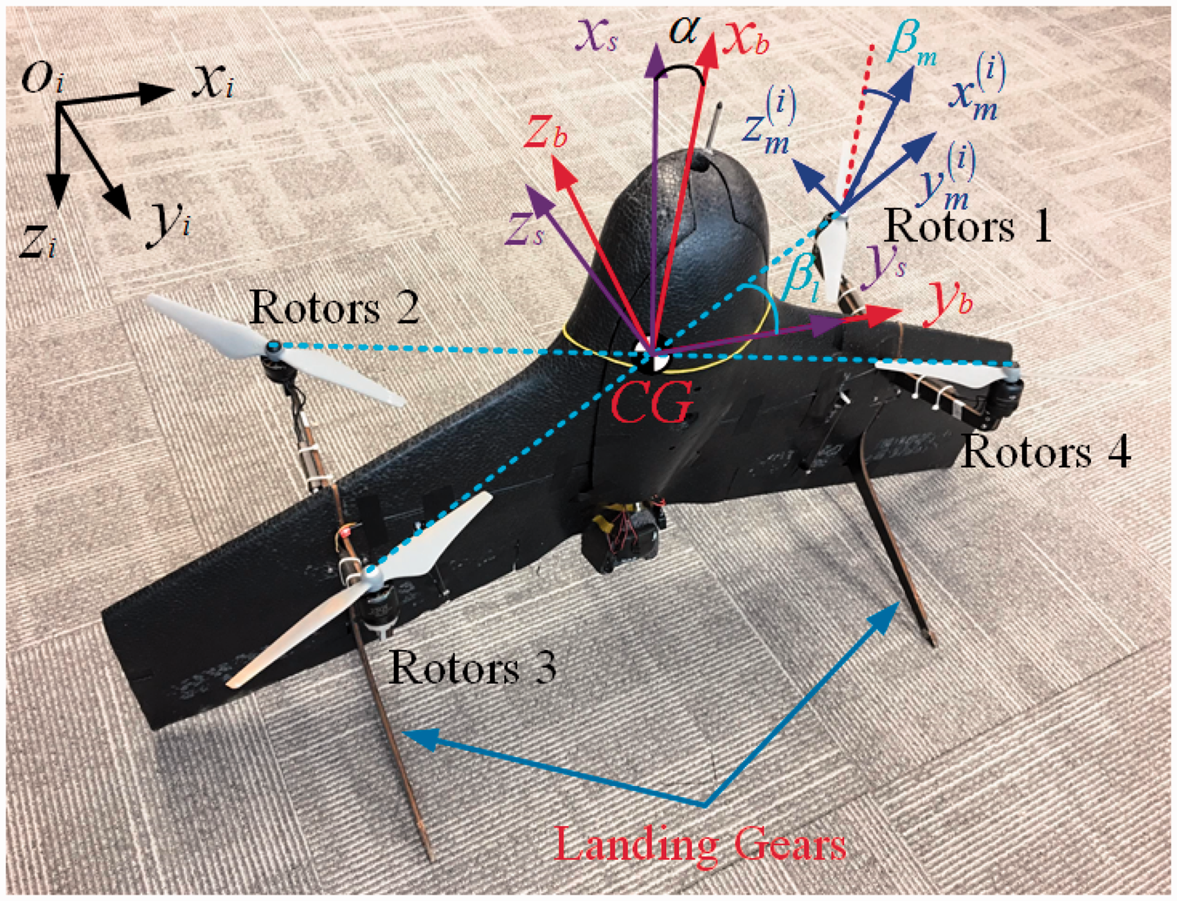
The quadrotor tail-sitter with frames defined in the Modeling section and specifications shown in Table 1.
The tail-sitter VTOL UAV specification.

In our previous work, 21 we have presented a complete model of a quadrotor tail-sitter, including full envelope aerodynamic model, propeller aerodynamics, motor dynamics, UAV kinematics and dynamics with all minor effects such as gyroscopic effects, motor acceleration/deceleration effects, and implemented the corresponding simulation. In this paper, wind tunnel tests are performed on the full-scale vehicle and the propulsion system, respectively, to capture the vehicle three-dimensional (3D) aerodynamic parameters and propeller aerodynamic coefficients to replace the original one (the corresponding test results are submitted along with this paper). The comparison of simulation results and experimental results show that the developed model is very accurate. A unified attitude controller and a stable transition controller are designed and the experiment results show that the developed attitude controller can stabilize the UAV attitude over the entire flight envelope which enables the vehicle to fly at a wide flight speed envelope ranging from stationary hovering to fast level flight, and the transition controller can successfully transit the UAV between vertical flight and level flight with negligible altitude dropping/gaining.
Modeling
Coordinate systems
Four coordinate systems are used in this paper. As shown in Figure 1, they are inertial frame, body frame, stability frame, and rotor frame. The origin of the inertial frame (shown as Oi) is set at the take-off point with xi, yi, and zi, respectively, being aligned with North, East, and Downside. The body frame (denoted by xb, yb, and zb) is defined to be the same as that of conventional fixed-wing aircrafts. To ease the aerodynamics analysis, the stability frame is commonly used. The stability frame is defined by rotating the body frame along yb by
Kinematics
The kinematics of the vehicle can be divided into two parts: translation and rotation. The translation part describes the displacement of the center of gravity (CG) of the aircraft which can be written as


According to Schaub and Junkins,
24
a generally rigid body only needs three independent parameters to parameterize the attitude. However, the rotation matrix has nine parameters which are highly redundant and will increase the computing complexity. To reduce such redundancy, a number of three-parameters methods have been developed, such as Euler angles or Tait-Bryan angles through three successive rotations, parameterization methods developed by Tsiotras and Longuski
25
through two successive rotations, and angle-axis method through one single rotation. Unfortunately, it has been proven that none of the three-parameters methods can be singularity free.24,26 A good balance between the singularity free and parameter redundancy is the quaternion-based parameterization method, which is singularity free while keeps only one redundant parameter. The attitude propagation using quaternion representation is written as
22


The quaternion is ideal to update the attitude in the simulation as it is singularity free and has few redundant parameters. However, it is hard for visualization and human interpretation. In conventional aircraft analysis, ZYX Tait-Brant angles are mostly used.
22
It is human intuitive but has singularity at pitch angle of ±90°. For the tail-sitter UAV, the vehicle is designed to transit from level to vertical flight by tilting its pitch angle nearly 90°, resulting in numerical instability for ZYX Tait-Brant angles. To avoid such singularity,
21
we choose ZXY Tait-Brant angles to represent the attitude that are used to monitor the aircraft attitude or accept human pilottd command. With the ZXY Tait-Brant angles, the singularity point is successfully shifted from 
Rigid body dynamics
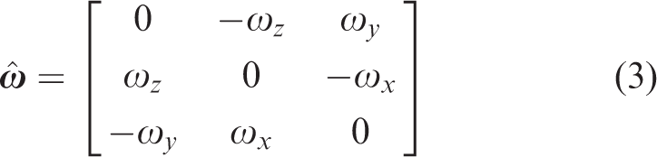
We consider the vehicle to be a rigid body when building its dynamic model. Using the Newton–Euler equation, we can derive the rotation and translation dynamic of the vehicle as follows


From equation (9), it can be seen that the total force
Actuator dynamics
According to Brandt and Selig,
27
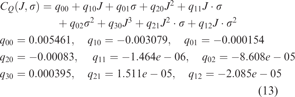
the propeller thrust and torque can be parameterized as follows

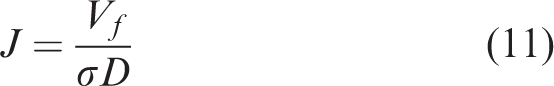
To parameterize CT and CQ, a wind tunnel test was conducted with the test platform shown in Figure 2. The motor–propeller pair is directly installed on a six-axis force sensor to measure its thrust and torque. A constant voltage source is used to provide and measure the power (i.e. voltage and current) for the tested motor and propeller. Through a specially designed strut, the whole test platform is connected to a rotation table, which is used to adjust the orientation of the inflow air. The rotation axis of the rotor xm is designed to be parallel to the ground. The wind speed generated by the wind tunnel is adjusted by tuning the fan voltage. A pitot tube (shown later in Figure 6) is used to measure the airspeed (i.e. the forward speed Vf for the propeller) of the wind tunnel. Through changing the PWM of the electric speed controller (ESC), we can adjust the speed of the rotor. The relationship among rotor speed, PWM, and forward speed Vf is shown in Figure 3. The data measurement process is as follows: (1) given a preset fan voltage and PWM, we wait for 30 s to make sure that the wind in the wind tunnel is constant and the propeller is rotating at a steady speed and (2) record the corresponding data with 10 s to get the mean value.

The propulsion system wind tunnel test.

The relationship among forward speed Vf, PWM, and rotor speed.
Similarly, we can obtain the relationship of thrust, torque, and power (the total power consumption of the propulsion system, gotten by multiplying the current and voltage), respectively, versus rotor speed and forward speed as shown in Figure 4(a), (c), and (e) by varying rotor speed and forward speed. Figure 4(a) and (c) is a two-dimensional graph with a legend of different constant wind velocities. Figure 4(e) is a 3D graph with the raw data and fitted curve. Using the results from Figure 4(a) and (c), we can further parameterize CT and CQ with respect to advance ratio J and rotor speed. MATLAB 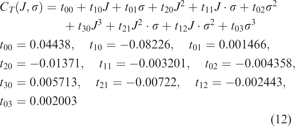
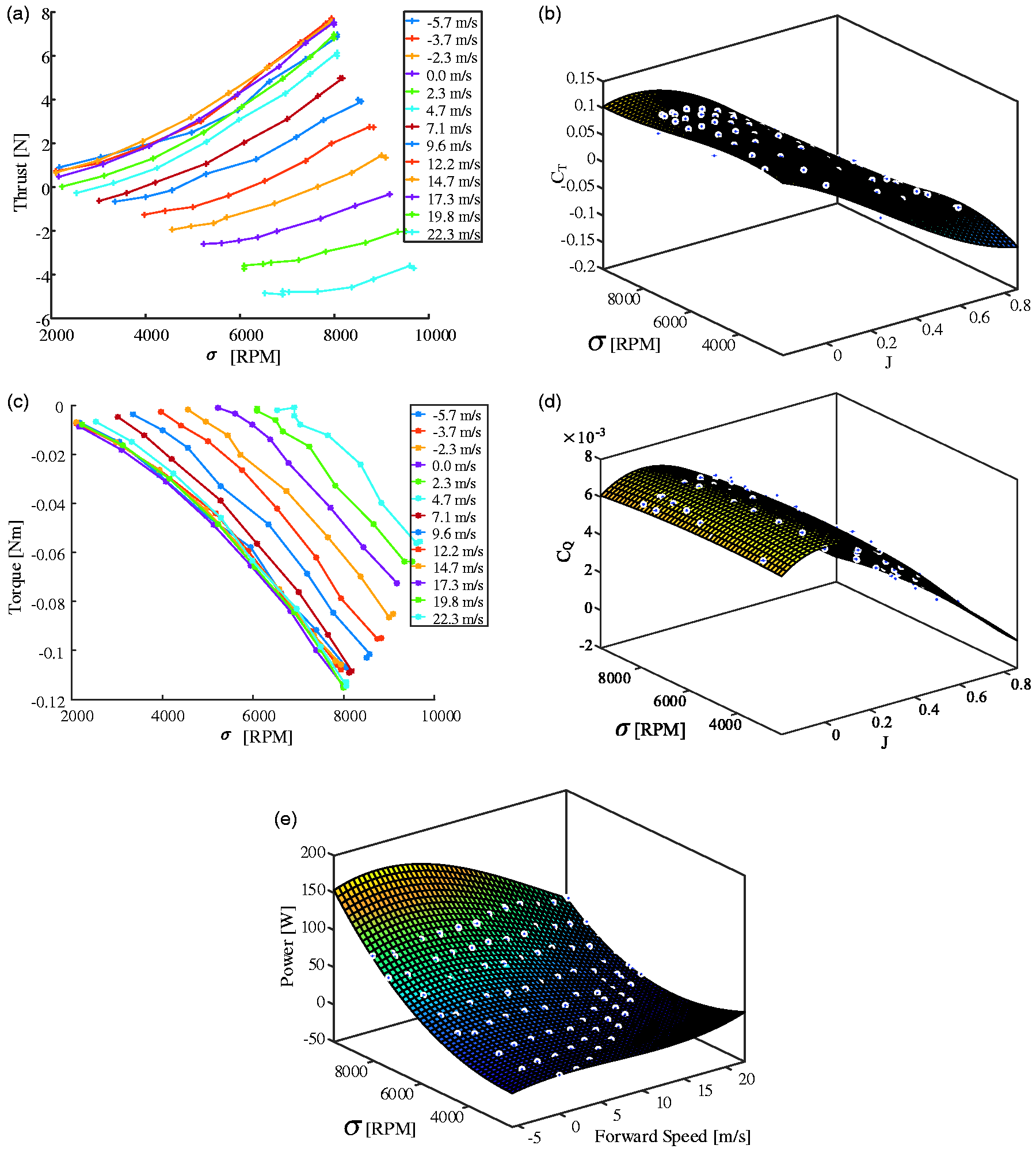
Propulsion system test data and fitting results. (a) Relationship among thrust, rotor speed, and forward speed, (b) Relationship among CT, rotor speed, and advance ratio J, (c) Relationship among torque, rotor speed, and forward speed, (d) Relationship among CQ, rotor speed, and advance ratio J, and (e) Relationship among power, rotor speed, and forward speed.
According to Theys et al., 28 the inflow angle will also affect the thrust and moment of the propeller. In the worst case, the error is approximately 10%. Currently, we only consider the inflow along xm axis, which is the principal factor to the thrust and moment of the propeller.
Airframe aerodynamics
The aerodynamic force 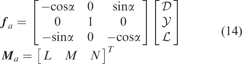


Aerodynamic frame, force, and moment. (a) Aerodynamic frame, force, and moment 3D and (b) Aerodynamic frame, force, and moment in longitudinal direction.
The angle of attack α and sideslip angle β can be calculated as follows

In order to calculate the aerodynamic force and moment at all possible angles of attack and sideslip angles that are likely to encounter in real flight, a full-scale vehicle (without propellers) wind tunnel test is conducted to parameterize the aerodynamic coefficients, as shown in Figure 6. The vehicle is fixed at the center of the wind tunnel on a rotation table that is used to adjust the vehicle yaw angle (sideslip angle). The UAV pitch angle can be adjusted by a rotation mechanism installed right below the UAV (see Figure 6 full-scale wind tunnel test). The wind speed level is adjusted by the voltage input to the wind tunnel fan. A six-axis force sensor is installed at the center of the rotation table to measure the aerodynamic force and moments. And a pitot tube is placed at the UAV shoulder to measure the actual airspeed. Similar to the data gathering method for the propeller, we collect the mean value of the measured data, including the wind speed measured by the pitot tube, UAV pitch angle read from the rotation mechanism, UAV yaw angle read from the rotation table, and the aerodynamic forces and moments measured by the six-axis force sensor, after the wind speed produced in the wind tunnel is steady. With the UAV pitch and yaw angle, we compute its angle of attack and sideslip angle. Meanwhile, we compute the aerodynamic lift, drag, side force, and moments by projecting the measured forces and moments to the corresponding directions. With these aerodynamic forces, moments, wind speed, and UAV wing area as the reference area, we compute the aerodynamic force and moment coefficients by equation (15). In the experiments, we adjust the rotation mechanism and also the rotation table such that the angle of attack reaches the full range of (
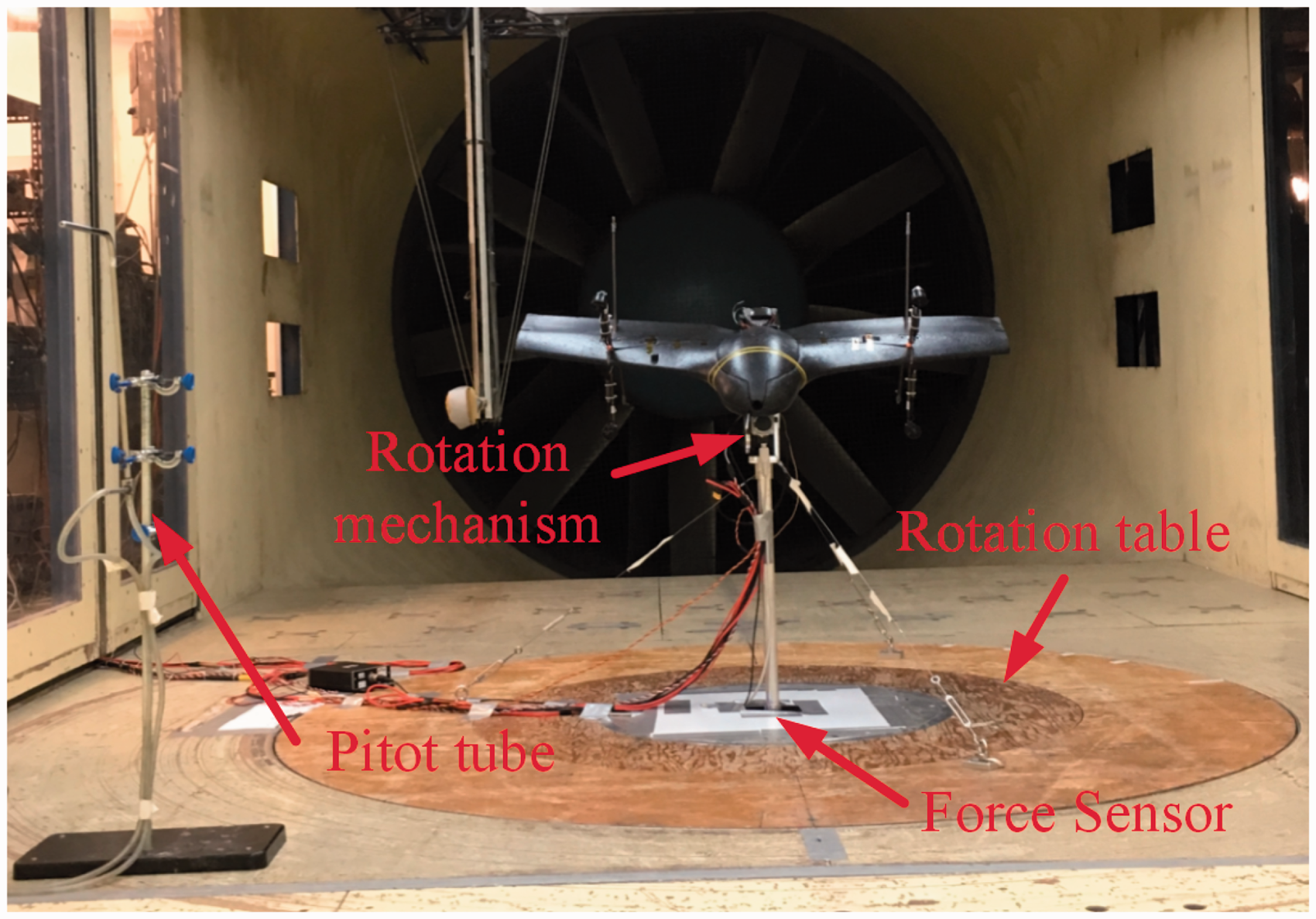
Full-scale wind tunnel test.

The interpolated aerodynamic coefficients. (a) Lift coefficient CL, (b) Roll coefficient Cl, (c) Drag coefficient CD, (d) Pitch coefficient Cm, (e) Side force coefficient CY, and (f) Yaw coefficient Cn.
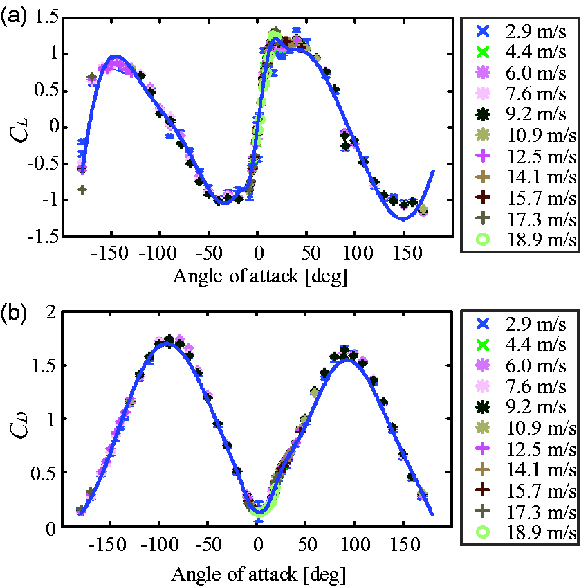
Longitudinal aerodynamic coefficients (a) Lift coefficient CL. and (b) Drag coefficient CD.
The comprehensive modeling and wind tunnel test lead to a complete and accurate flight simulator. We will defer the simulator development in the Simulation implementation section and look into the controller design in the sequel discussion.
Controller design
Attitude and transition controller design
Our controller consists of two parts: an attitude controller and a transition controller. The attitude controller is used to track the attitude to the desired one in all flight envelopes. As shown in Figure 9, the attitude controller is a cascaded controller based on SO(3). The outer loop and the inner loop are, respectively, angular loop and angular rate loop. The outer loop is a proportional controller, the desired angular rate 


Attitude controller diagram.
The transition controller is developed to hold the UAVdl altitude during the transition process, which is particularly useful for accurate and stable transition flight. The altitude dynamics can be represented as follows


The resulting thrust is therefore

Mixer
After the control thrust fTx and moment
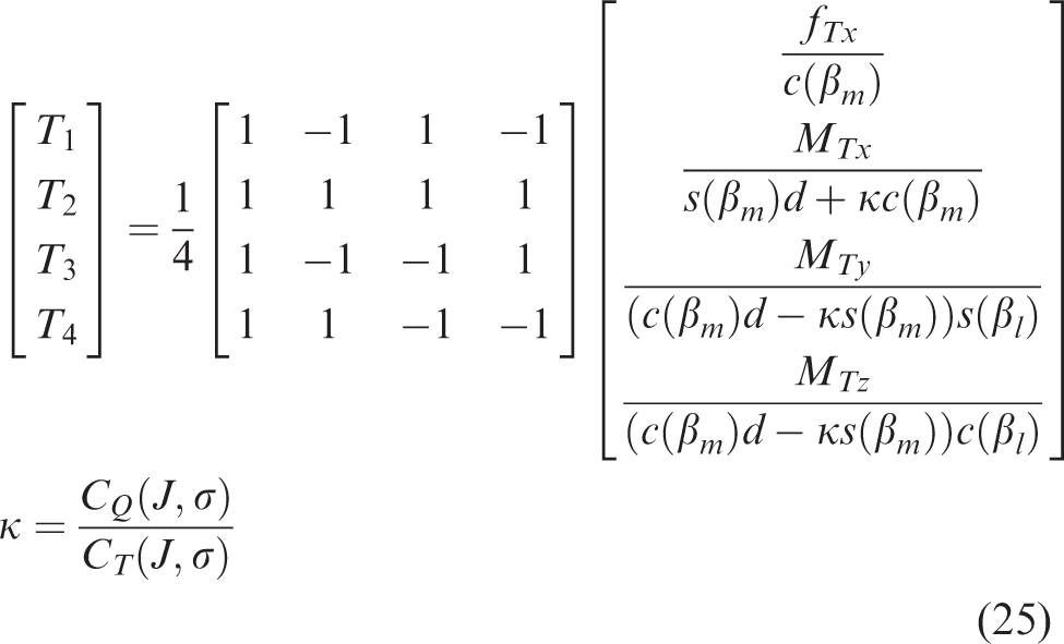

The relationship among

The relationship between rotor speed and PWM with Vf = 0.
Simulation implementation
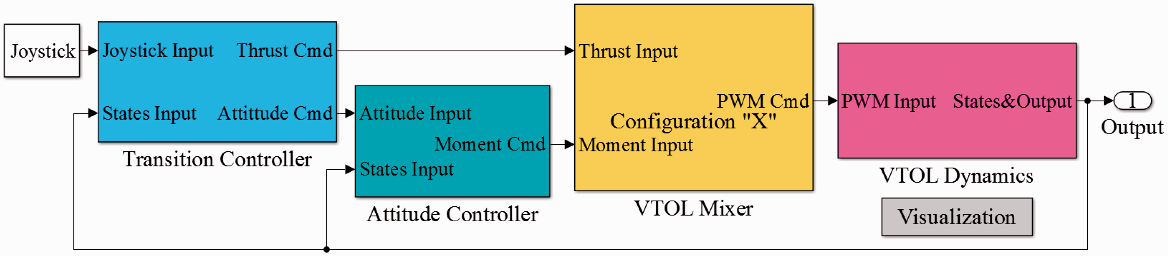
In the Modeling section, we have built the completed model of our vehicle and obtained all the required parameters through corresponding experiments. Combining the kinematics and dynamics model, the designed controllers, and the mixer, we implement a flight simulator in MATLAB Simulink as shown in Figure 12. The simulation is highly modularized, including Joystick, Transition Controller, Attitude Controller, VTOL Mixer, VTOL Dynamics, and Visualization module. The Joystick module is used to send the human pilot commands including attitude command, altitude command, and transition command. The Transition Controller module is used to calculate the thrust and send attitude command during the transition process. The Attitude Controller module receives the attitude command to calculate the desired control moment. The desired thrust and moment are then sent to the VTOL Mixer module to allocate the control action. The PWM commands are finally sent to VTOL Dynamics module which has been detailed in the Modeling section. The Visualization module can simultaneously show the attitude and position of the vehicle as shown in Figure 13, which demonstrates an example transition from vertical flight to level flight and then back to vertical flight. After the simulation is completed, all the simulation results are saved as a flight log for further analysis.
The VTOL UAV simulation platform implemented in Simulink.

The simulation visualization results.
Transition flight simulation
As we mentioned earlier, the vehicle is capable of both level flight with better power efficiency and vertical flight for hovering. To achieve this, a transition maneuver between these two distinctive flight modes is required. We show in the simulation that the previously designed controller can achieve this goal very well. In the simulation, the attitude controller is fed with a linear decreasing pitch angle command for the forward transition flight (from vertical flight to level flight) from the transition controller. Similarly, a command with a linear increasing pitch angle is used for the backward transition (from level flight to vertical flight). The simulation results are shown in Figure 14(a). During the transition process, the commands of roll, yaw, and altitude are all set to be constant. We can see from the simulation results that the pitch angle can be tracked very well except the backward transition process. However, the roll and yaw angles can be well tracked with the maximum absolute error less than

Transition between level flight and vertical flight. (a) Simulation results and (b) Experimental results.
Flight envelope simulation
In the simulation, we set a series of commanded pitch angles with a constant altitude command. With the designed attitude and altitude controller designed in the Controller design section, the aircraft can track the desired pitch angles quite well without any significant altitude variation. Once reaching a steady state, the aircraft flight speed can be recorded. This flight speed is equal to the airspeed as no wind is simulated. As a consequence, the steady flight speed versus different pitch angle (i.e. the angle of attack) is obtained. The simulation results are shown in Figure 14, which shows that our vehicle can fly at any angle of attack between

PWM of the motors for Figure 14(b).
Using the relationship between thrust and airspeed at different angles of attack as shown in Figure 16 and the fitted rotor parameters in Figure 4(e), the power consumption of our vehicle is estimated as follows:
First, we obtain the required total thrust at steady flight from Figure 16. And divide this total thrust by 4 to obtain the required thrust of each motor. By doing this, we are assuming that the vehicle flies at the trim condition which means the aerodynamic moment equals to zero. Thus, four rotors are considered to be working in the same condition. From the same Figure 16, the steady level flight speed is read, based on which we calculate the forward speed of each rotors as Using the relationship among the forward velocity, thrust, and rotation speed in Figure 4(a), we estimate the speed for each rotor. Provided with rotation speed and forward speed in previous steps, we finally estimate the total power consumption using the fitted power consumption shown in Figure 4(e).
The estimated power consumption is shown in Figure 17, where we can see that the power decreases from 132.5 W to 76.02 W while the vehicle pitch forward from

The relationship between angle of attack, velocity, and thrust.

The relationship between estimated power and angle of attack/airspeed in simulation.
Flight experiments
Transition flight verification
During the transition flight verification process, a decreasing and increasing pitch command was, respectively, used to achieve forward and backward transition, similar to that used in the simulation. The experimental results are shown in Figure 14(b), which shows that our vehicle can accomplish the transition flight without gaining/dropping significant altitude (gains 0.38 m in the forward transition flight, drops 1.25 m in the level flight, and gains 1.85 m in the backward transition flight) and the attitude can be well tracked with maximum roll error less than 5° and yaw error less than 3.5°.
Comparing Figure 14(a) and (b), we can find out that the commanded attitude and altitude in simulation and experiment are the same. The transition flight verification shows that our simulation platform can predict the flight status of our vehicle quite well from the following aspects: (1) The pitch tracking performance is very similar for simulation and experiments, for both forward and backward transitions. For example, both the simulation and experiments show accurate pitch tracking during the forward flight, but a considerable tracking delay during backward transition. (2) The simulation shows that the vehicle gains around 2 m during the backward transition, which is also observed in the real flight. (3) Both roll and yaw directions are tracked quite well during the whole process.
Figure 15 shows the commanded PWM of the outdoor flight test for Figure 14(b). The red line and yellow line are, respectively, the upper bound and lower bound of the commanded PWM. As we can see, during the backward transition, the altitude of the vehicle has increased to around 2 m. To hold the desired altitude, the commanded PWMs are quite small (from 12 s to 14 s), which will decrease the control moment. However, the aerodynamic moments in pitch direction are quite significant due to the high airspeed at the beginning of the backward transition. The large aerodynamic moments exceeds the control moment provided by the motor–propeller pair leads to the pitch tracking error.

The relationship between lift-drag ratio and angle of attack.
Flight envelope verification
Similar to the flight envelope simulation detailed in the Flight envelope simulation section, we conduct several flight experiments and set different pitch commands as the angle of attack in each experiment. The corresponding angle of attack and steady cruise speed are recorded during the flight experiment. A pitot tube is rigidly installed along xb axis to measure the airspeed. However, this will lead to inaccurate and sometimes false airspeed measurement at high angle of attack. To solve this problem, we conducted our experiment in a clear day with very low wind. In this way, the vehicle ground speed, which can be measured by its global positioning system (GPS), can be used as the airspeed. To maximally cancel out the effect of residual wind, we conduct our experiments as that shown in Figure 19. We first measure the wind direction at any wind speed and then command the UAV to fly along and against the wind reversely to get the mean cruise speed. The results are summarized in Figure 20. It can be seen that the actual flight results agree with our simulation surprisingly well, which implies the effectiveness of our simulation model. The slight residual error may be caused by the uncompensated residual wind and ground speed measurement errors. Figure 21 plots the log data of some sample flights with

Outdoor test methodology.
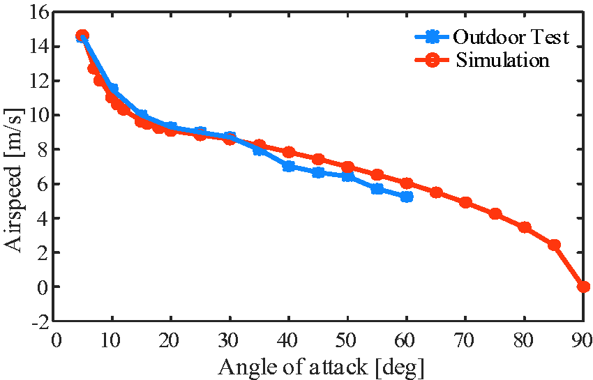
The relationship between angle of attack and airspeed.

Vehicle ground speed versus different pitch angles during outdoor test. (a) Ground speed versus pitch angle 60°, (b) Ground speed versus pitch angle 30°, and (c) Ground speed versus pitch angle 10°.
Conclusion
In this paper, we build a detailed model of our quadrotor tail-sitter, including the kinematics, rigid body dynamics, actuator dynamics, and airframe aerodynamics. Extensive wind tunnel tests are conducted to obtain the coefficients of actuator dynamics and airframe aerodynamics. A transition controller and a unified attitude controller are designed to accomplish the vertical flight, level flight, and transition flight. A Simulink simulation platform is implemented and the corresponding transition flight simulation and flight envelope simulation are conducted. Simulation results that our vehicle can accomplish transition between hovering flight and level flight with insignificant altitude error and the ability to fly at a wide flight envelope from
Footnotes
Declaration of conflicting interests
The author(s) declared the following potential conflicts of interest with respect to the research, authorship, and/or publication of this article: This research is supported by Hong Kong ITF Foundation (ITS/334/15FP) and DJI Joint Lab Foundation.
Funding
The author(s) disclosed receipt of the following financial support for the research, authorship, and/or publication of this article: This research is supported by Hong Kong Innovation Technology Commission (ITC) under ITS/334/15FP and the DJI Scholarship from the HKUST-DJI Joint Innovation Laboratory (HDJI).