
Abstract
This paper describes the design and development of the Dove, a flapping-wing micro air vehicle (FWMAV), which was developed in Northwestern Polytechnical University. FWMAVs have attracted international attentions since the past two decades. Since some achievements have been obtained, such as the capability of supporting an air vehicle to fly, our research goal was to design an FWMAV that has the ability to accomplish a task. Main investigations were presented in this paper, including the flexible wing design, the flapping mechanism design, and the on-board avionics development. The current Dove has a mass of 220 g, a wingspan of 50 cm, and the ability of operating fully autonomously, flying lasts half an hour, and transmitting live stabilized color video to a ground station over 4 km away.
Introduction
Natural flying birds, bats, and insects utilize flapping wings to fly, which has been an inspiration to human being for hundreds of years. Researchers have indicated that the flapping flight may offer some unique aerodynamic advantages over the traditional fixed wing or rotary flight when the feature size is in small scale,1–3 which inspired research interests in the flapping-wing micro air vehicle (FWMAV). Over the past two decades, numerous efforts have been exerted to develop the FWMAVs, and several typical FWMAVs are shown in Figure 1.

The Nano Humming Bird 4 shown in Figure 1(a) was unveiled by AeroVironment in 2011. It had a mass of 19 g and a wingspan of 16.5 cm. It could hover for 11 min with approximately 30 Hz of flapping frequency, fly forward up to 6.7 m/s, and transmit live color video to a remote ground station. The vehicle demonstrated hovering flight only with two flapping wings.
The SmartBird 5 shown in Figure 1(b) was unveiled by Festo in 2011. It had a mass of 450 g and a wingspan of 200 cm. Inspired by the herring gull, it could start, fly, and land autonomously, with no additional drive mechanism.
The BionicOpter 6 shown in Figure 1(c) was unveiled by Festo in 2013. It had a mass of 175 g and a wingspan of 63 cm and was inspired by the dragonfly. Its four wings could be adjusted individually to move in almost any orientation in space. There are 13 degrees of freedom for its unique flight maneuvers.
In addition to the above introduction, there are still many outstanding technologies that have been made in some representative FWMAVs,7–15 the details of which will not be described here.
In response to the research upsurge of FWMAVs, a series of studies were carried out in Northwestern Polytechnical University (NPU) since 2000. Through great efforts for more than a decade, a significant development has been achieved: Dove—a flapping-wing micro air vehicle, including flight control system, miniaturized on-board avionics, and tiny functional payloads.
Specifications of the Dove and other FWMAVs are different. The Nano Hummingbird was more focused on the hover performance in specific limited space. Festo’s SmartBird and BionicOpter were technique demonstrators rather than products for practical applications. The Festo company did not plan to sell SmartBird or BionicOpter and denied any interest in military applications at present. 16 Thus, the design emphases between them were quite different.
The Dove was more focused on the performance of application, as well as the flying capability in specific conditions, whose integration of essential components and the practical performance. Dove has the appearance of a biological pigeon and is capable of fully autonomous flight (including the climbing after launch and the descending before landing). Live colored video can be captured by a tiny on-board digital camera and is processed by a ground station computer in real time to eliminate the image oscillating caused by the inherent oscillation of flapping flight, so that operators can identify objects easily according to the video.
This paper introduced these necessary and key technical achievements and evolution of development, trying to show how Dove came into being.
Research history and evolution
Flying prototypes research
Due to the indistinction of theoretical foundation and lack of development experience, there were great difficulties in designing a set of subsystems and integrating them to the final aircraft, especially on such a highly unusual micro air vehicle utilizing flapping wings to fly. As a result, the flapping-wing micro air vehicle was refined in several evolutionary steps, with numerous prototyping and flight test.
Remarkable archetypal representatives are shown in Figures 2 to 4, and the final design of Dove evolved from the following stages: (I) Explorations of the principles of flapping flight, (II) interim prototype development and on-board avionics flying test, and (III) system integration and final aircraft refinement.
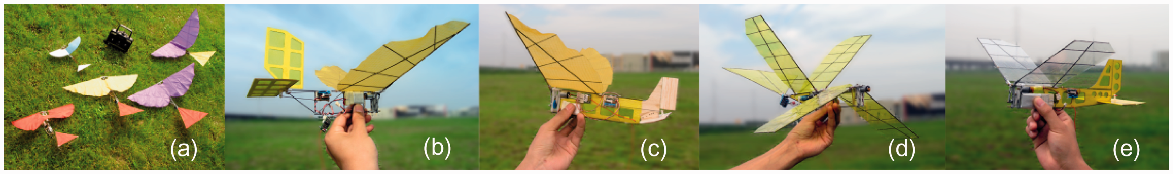
Prototypes of stage I. (a) PY1-PY5 aircraft, (b) PY8A aircraft, (c) PY8B aircraft, (d) PY10 aircraft, and (e) PY12 aircraft.

Prototypes of stage II. (a) PY16 aircraft, (b) PY16B aircraft, and (c) PY17 aircraft.

Prototypes of stage III. (a) PY19 aircraft, (b) ASN-211 aircraft, and (c) Dove aircraft.
Table 1 presents the prototypes in chronological order and summarizes significant features of these representative prototypes. Prototypes built in the stage I were used to recognize the fundamental principles of flapping flight, such as the studies of flapping mechanisms, control philosophy, inherent stability, the overall configuration, wing structure, geometry, feasible materials, and so on. In other words, the elementary goal of this stage was to solve the problem that the flapping-wing aircrafts were capable of flying and easy to control.
Flight test prototypes.

Profits from the foundation of stage I, further works were carried out in stage II, were performable but also more challenging. Only if the aircraft had a tremendous upswing in flying capability to carry relative heavy avionic prototypes and flied as long as possible, so that the on-board avionics’ flying test could be performed. In this stage, an enlarged interim prototype PY16 with 1 m wingspan was developed. It satisfied the expectation that flying capability could be enhanced through a larger wingspan; but short endurance was an unfavorable derivation due to the increase in the power consumption corresponding to the expansion of wingspan. Nevertheless, this interim prototype, with a net loading capacity of more than 80 g, carried out a series of flying experiments to check the function and performance of the avionics.
In stage III, efforts were focused on the ultimate flapping-wing micro aircraft development and system integration. Difficulties were reflected in downsizing, increasing efficiency, and making avionics electromagnetic compatible. The final size of the FWMAV system was determined to be no larger than 50 cm, which was similar to the pigeons that is half the size of PY16, but the loading weight remains approximately equal. So one of the important breakthroughs was that the efficiency of flapping-wing system was greatly improved, mainly refer to the improvements of the wing itself, and for the first time PY19 had the ability to takeoff with approximate 100 g net loading, which was equal to the weight of itself. Furthermore, PY19 was integrated with an on-board flight control system, this unique system specially designed for flapping wings made PY19 capable of autonomous flight.
Further refinements were made in prototype ASN-211, the system was added with live colored video transmission and telecommunication ability, and was unveiled at the 8th China International Aviation & Aerospace Exhibition for the first time in 2010.17 The final prototype was named as “Dove,” the purpose of this final variant was to meet the requirement of biomimetic, not only in flight characteristic but also in appearance. This prototype was a modification of ASN-211, with the biological pigeon inspired appearance.
Performance overview
The Dove is shown in Figure 5, the specifications are given in Table 2.

Constitution of the Dove aircraft (shown with right body panel removed).
Specifications of the Dove.

Development and design
Flapping-wing design
Unlike the traditional fixed or rotary wing flight, in the case of flapping-wing aircraft, the wing design is one of the most important topics, since the flapping wings are the only source of generating both lift and thrust. A significant challenge in wing design is that the wing is heavily influenced by the low Reynolds number effect (typically between 5 × 10⁴ ∼ 10 × 104 for Dove) and unsteady dynamic characteristics of flapping, both structurally and aerodynamically, as well as planform, structure, and airfoil design.
Considering the wingspan size of Dove, active deformation of the wing was thought to be infeasible, given the state of actuator technology and the resources available at that time. Meanwhile, previous numerical studies indicated that the passive deformation of the flexible wing was adequate for lift and thrust production.18,19 Therefore, our primary object in wing design was to develop wings with flexible membrane with passively dynamic deforming properties.
The process of wing design can be summarized in Figure 6. Compared to the conventional aircraft design, there was no sophisticated approach in flapping-wing design, so we carried out the process in the loop of theoretical and experimental based design → fabrication → test → refinement, which was so far the most realistic and valid pathway.

Diagram of wing design process.
A scale law, which was a biological statistics in mathematical expression compiled by Shyy et al., 20 was applied in the conceptual design process, the initial design parameters such as wing span, wing area, wing loading, aspect ratio, and beat frequency were assigned roughly.
Tentative studies of experimental and theoretical approach were carried out in the preliminary wing design process, some common features of unsteady low Reynolds number aerodynamics of flapping wing were obtained. Preliminary experiments were carried out in a low turbulence wind tunnel of NPU. Early results 21 indicated that the thrust was strongly affected by the unsteady effect of the flapping motion, and the lift mainly depends on the flying speed and the angle of attack. This meant that in level flight, a birdlike flapping wing’s majority of lift was generated in the way similar to the fixed wing aircraft, and the thrust was produced mainly by the wing deformation during flapping. By learning this discipline, the basis of designing an aerodynamic efficient flapping wing could be made more clear; the main object was to obtain a maximum lift-drag ratio and a maximum thrust coefficient.
Early results 22 also showed that the flapping wing with larger aspect ratios gained higher lift-drag ratio, this was identical to the common rules existed in fixed wing aircrafts. Even so, the aspect ratio of Dove’s wing should not be enlarged infinitely, considering the structural strength and the power consumption, and was initially set to 7 according to the scale law.
The effects of different taper ratio have been analyzed. The lift coefficient was decreased when the taper ratio increased and the inner part’s stiffness reinforced, meanwhile the thrust coefficient (negative drag coefficient) increased. 22 It could be inferred that the inner part of wing mainly contributed to lift generation, as well as the outer part of the wing was the main source of thrust, where deformations mainly dominated. Therefore, a robust flapping-wing design should have sufficient lifting surface with a relative lift coefficient in the inner part to generate a certain extent of lift and a flexible trailing edge area in the outer part to produce considerable thrust, and the planform should be approximately a trapezium to meet a preferable taper ratio. However, the tip area of flapping wing had a dominant effect on power consumption, resulting in the wing tip area should be restricted, a chamfer angle on trailing edge would be a reasonable way to meet such requirements.
Studies23,24 showed that airfoil’s positive camber will help to raise the lift in flapping flight, but also brings about the shortcomings of thrust loss, so the inner part of flapping wing should have a greater airfoil camber than the outer part to produce the best result of lift and thrust generation.
Research works25,26 show that the flexibility of the membrane wing would dominate the aerodynamic characteristics, a parametric study was primarily carried out to investigate the effects of wing deformation on aerodynamic characteristics, so as to determine the rigidity distribution of the flexible wing. The preconditioned Reynold-averaged Navier–Stokes equations, based on chimera grid, 27 were developed to implement this numerical study. Deflection in span wise and chord wise was separately placed on the flapping wing and the corresponding aerodynamic results are shown in Figure 7. The results suggested that span-wise deformation should be limited in a small degree to achieve higher aerodynamic performance; in addition, chord-wise deformation was good for aerodynamic force generation, especially for thrust production. Therefore, the design of the flexible flapping wing should be as follows: the inner part of the wing ought to possess a high lift profile with more rigid structure and the outer part of the wing should be more flexible than the inner part to get required chord-wise deflection.
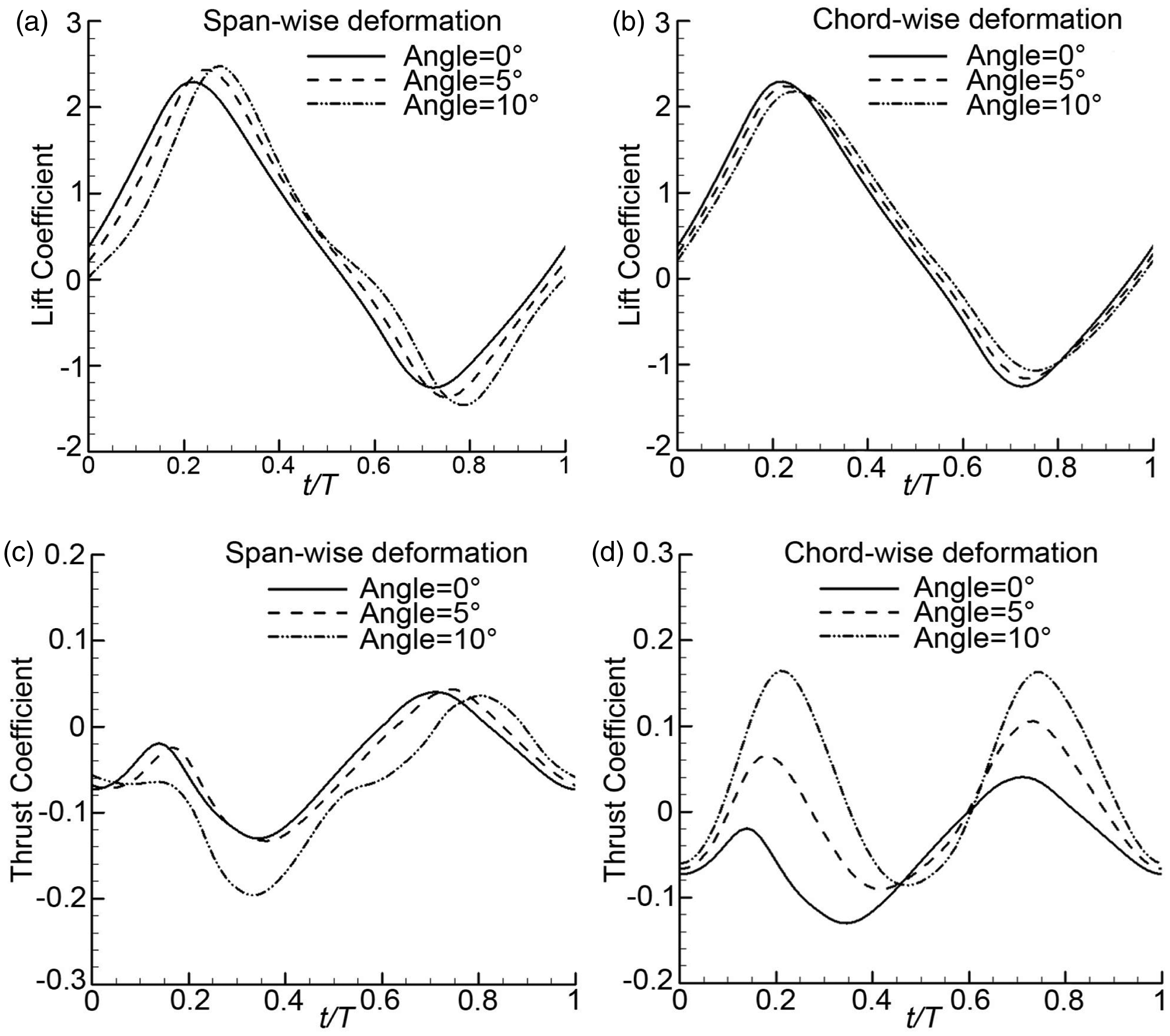
The effects of wing deformation on instantaneous aerodynamic coefficient.
More sophisticated structural design was done using a self-developed computational fluid dynamics/computational structural dynamics (CFD/CSD) solver. 28 The solver was able to carry out aerodynamical/structural coupled simulations; structural distortion caused by inertia force was also taken into account. After testing material properties including carbon fiber rods, Mylar and resin adhesives, three different structure frames were investigated, as well as the ribs and the airfoils, some selected results are shown in Figure 8.

Aeroelastic analysis of the flexible wing with different structural frames (α = 0°, V = 8 m/s, Φ = 70°, f = 9 Hz). (a) Maximum span-wise bending angle in a flapping cycle; (b) Maximum chord-wise twisting angle in a flapping cycle; (c) Instantaneous lift coefficient in a flapping cycle; (d) Instantaneous thrust coefficient in a flapping cycle.
Figure 8 shows that the wing with approximate triangular frame and longitudinally arranged ribs (first wing in Figure 8) obtained maximum lift and considerable thrust, it could be inferred that the deflection of the wing should be in appropriate amounts both in span wise and chord wise. Such architecture would manage to preserve high lift profile of the inner part of the wing and readily produce reasonable twist in the outer part, thus to look after both sides of lift and thrust generation.
Wind tunnel experiments had concluded that proper camber of the wing would help to raise the aerodynamic forces, therefore an airfoil was then introduced to the wing structure. The airfoil of the flapping wing was derived from the species of the migratory birds, and airfoil Epper 378 was chosen for the similar top surface shape and the possibility to apply to membrane wing. The rib was designed half convex in cross-section in order to generate unsymmetrical deformation during the up-stroke and down-stroke, so as to produce extra lift from the unsymmetrical twist shown in Figure 9. It could be seen that the deflections of the flexible wing were arranged along the oblique spar, so that the inner part of the wing preserved aerodynamic profile which was good to lift generation and the outer part of the wing twisted reasonably to produce needed thrust.

Structure of the flexible membrane wing and CFD/CSD results of deflection distribution.
The final design of the wing was exactly the same as shown in Figure 9; composite materials and polymeric materials were used in fabricating the flexible membrane wing, a single wing’s weight was 7 g, with a wing span of 50 cm and an aspect ratio of 7.4, capable of lifting a 220 g flapping aircraft flying in the speed up to 12 m/s.
The experimental results are compared with the computational results to verify the CFD/CSD solver, more detail can be found in the study by Yang et al. 23 The averaged aerodynamic performance of the wing is shown in Figure 10. We can see that, the intersection point of the residual thrust curve and horizontal axis is around 17 degree of angle of attack. Here the corresponding lift reached about 230 g, which is greater than the requirements of take-off weight of 220 g calculated in general design process. In this case, the lift is greater than gravity; thrust is equal to the drag. So the above flexible flapping-wing design can meet the requirements.
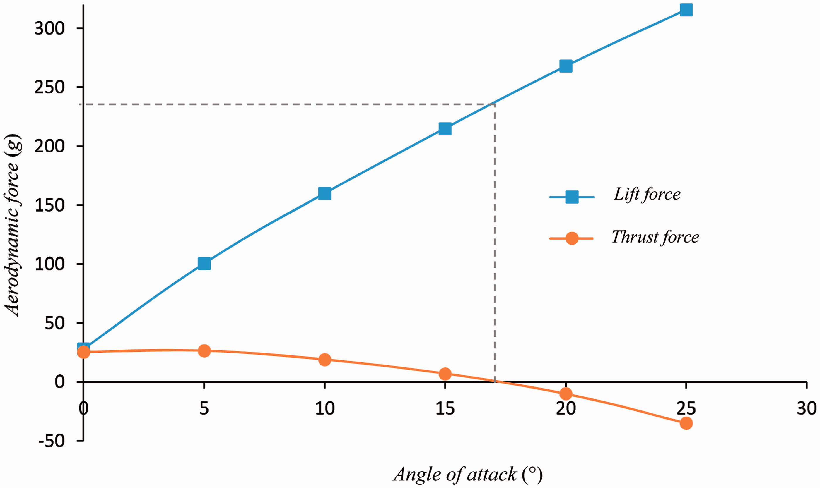
The averaged aerodynamic performance of the flapping wing.
3.2. Flapping mechanism design
Flapping mechanism was a sub-system that converts electrical energy of the onboard battery to mechanical flapping power of the wings, whose efficiency and robustness were the key issue. To design and fabricate light-weight, high-power flapping mechanisms, mass variants of four-bar linkage based flapping mechanisms using gears, cranks, bushings and levers have been explored as Figure 11 shown.

Designs of flapping mechanism. (a) Symmetrical flapping mechanism using a pair of crank-rocker, (b) symmetrical flapping mechanism with variant crank-rocker, (c) unsymmetrical flapping mechanism using epicycle motor, (d) unsymmetrical flapping mechanism added with wing folding mechanism, (e) miniaturized flapping mechanism utilize two main frames; and (f) final design of flapping mechanism using a single rack construction and unsymmetrical flapping four-bar linkage.
Figure 11. (f) was chosen to be the final design of flapping mechanism as a result of fuzzy optimization, 29 such design was high efficient and durable, despite with unsymmetrical movement between two rockers. The unsymmetrical movement of flapping mechanism was harmful to the stability of flapping flight. Although the movement differences between two wings are slight, the acceleration of two wings differs greatly due to the high-speed oscillation, which will cause serious wobbling in lateral and directional when the wings flapping. As a result, the four-bar linkage was carefully designed to address the issues associated with single-crank two-rocker mechanism, and meet the kinematics and dynamic characteristics simultaneously. The optimized parameters and the motion laws of four-bar-linkage flapping mechanism are shown in Figure 12, the average phase lag between two wings is 2.0 degree.

The optimized parameters and the motion laws of four bar mechanism, l1 = 7 mm, l2 = l3 = 38 mm, l4 = l5 = 12 mm, lAB = 20 mm, lOC = 37 mm, ω is the angular velocity, and a is the angular acceleration.
The flapping mechanism was compatibly designed based on the motor characteristics and the flapping-wing demands, so as to keep the global efficiency in a considerable level.
The blushless DC motor was well characterized by experiment, its results is shown in Figure 13:
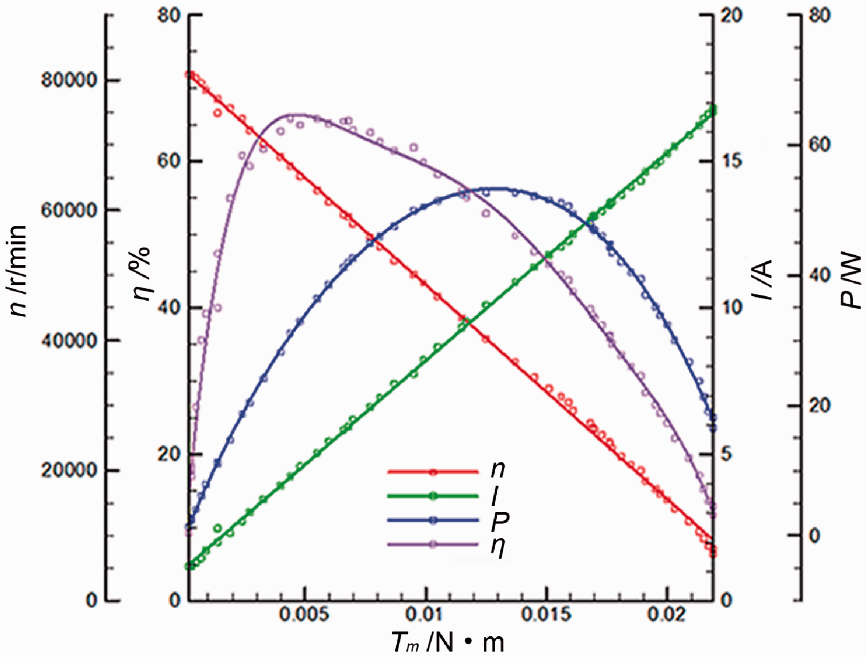
Motor characteristics.
Additional wind tunnel experiments were carried out to determine the driving demand of the flapping wing. Unlike former wind tunnel experiments carried out haphazardly, this testing should be consistent with practical flying conditions of flapping flight, mostly in steady level flight, which means that thrust T equals drag D, and lift L equals gravity G. But the set X={X | T = D, L = G} was impracticable to be obtained once and for all, the convenient way was to obtain sets Y={Y | T = D} and Z={Z | L = G} separately and then for intersection of them. Moreover, the experimental plans were usually unsuitable for sets Y and Z as well, interpolation method was used to process the experimental results and then to obtain the sets of Y and Z. Figure 14 were the processed results of the wind tunnel experiment of the predesigned wing.

Feasible flapping parameters.
As the figure shown, flying speed strongly affects the combinations of angle of attack, flapping frequency and flapping amplitude, while the flapping wing maintained in steady level flight. Although this phenomenon was common in biologic birds’ flight, altering the flapping amplitude during flying seemed to be infeasible by using the current manmade flapping mechanisms. Hence, a fixed flapping amplitude would be favorable in designing a flapping mechanism. Unexpectedly, the tested flapping wing had an intersection region marked by the circle as Figure 14 shown, where the flap amplitude was nearly same (73°) and shares the same flapping frequency of 8 Hz. It means that the mechanism would be designed conveniently with a fixed flapping amplitude, which makes the flapping wing could cover the flying speed from 6 m/s to 10 m/s.
The flapping torque Tw of the rocker was also obtained by a strain gauge on the root of the rocker, with respect to the feasible flapping parameter of Figure 14. (for instance, the flapping frequency is 8 Hz, and the flapping amplitude is 73°), the reduction ratio of gear and the length of four-bar linkage can be decided.
The final flapping mechanism, shown in Figure 15, was fabricated using Polyoxymethylene (POM) plastic, aluminum and titanium alloy materials. This flapping mechanism is the most successful one we had ever fabricated, it is robust and durable, weights about 35 g (include the 16 g blushless motor), and can drive the wings flapping at a frequency of 4–12 Hz.

Flapping mechanism of the Dove.
3.3. Avionics
It was envisioned that the FWMAV should have the ability of autonomous flight and information acquisition. However, for the peculiarity of FWMAV, there was no available equipment satisfying these requirements when the research program got under way, especially for the flight control system (FCS), as well as the data link and the information processing system (IPS). In view of this, a group of researchers majoring flight control, telecommunication, electronics and image processing had been gathered to solve the problem.
The nature birds’ actively control of the wings and the tail was thought to be far beyond imagine to apply on man-made FWMAVs, given the state of control technology and resources. Throughout history, most of the successful flapping-wing aircraft prototypes utilized tails as control devices, just similar to the traditional aircraft configuration. In consideration of the feasibility, we decided to use tail as control devices as well, which would make the design of the flight control system less difficult.
In spite of this, there was still a big problem associated with flapping flight, the extreme environment on-board the aircraft shown in Figure 16 leads to difficulties to autopilot the vehicle. Such airplane was a strongly nonlinear system, whose behavior would rapidly lead to divergence in attitude estimation and stabilizing, made the traditional auto control law inapplicable on flapping-wing aircraft anymore.

The acceleration and angular rate captured by onboard sensors during flying test.
For this reason, a new type of Unscented Kalman Filter (UKF) was introduced to a control algorithm to solve the problem of attitude calculating. Surprisingly, this control algorithm was originally designed for fixed wing aircraft, which left the vibration of flapping-wing untreated, and still worked well on the flapping-wing aircraft together with the new UKF. Therefore, it was not essential to design a brand new control algorithm with front-end treatment of vibration on flapping wings, and just left the job done ultimately by the actuators with relatively narrow bandwidth behaving like a low pass filter, it was a way for convenience in processing periodical nonlinear characteristics into time-averaging linear characteristics. Another reason why this control algorithm worked well on flapping-wing aircraft was that it adopted total energy control regulation to adaptively control the longitudinal flight parameters, made it adequate in controlling such an unstable aircraft that was easily influenced by gust due to the small moment of inertia and insufficient aerodynamic damping. The flow chart of design of the flight control system is shown in Figure 17 for the control of the FWMAV.

The flowchart of flight control system.
The final algorithm was made into a software running on the flight control system (FCS) shown in Figure 18, which was fully assembled with core components such as microelectromechanical systems (MEMS) rate gyroscopes, accelerometer, magnetometer, barometer, together with a GPS receiver, a microprocessor, and flash memories, provided by Chengdu JOUAV Automation Tech company. The flight control system was responsible for stabilizing and navigating the vehicle, interpreting and executing control commands from the ground operator, sending back telemetry to the ground station, and logging data. This subsystem had a mass of approximate 35 g, and was designed to fit into the pigeon-shaped body of the Dove.

Flight control system.
A digital data link subsystem combined with micro digital color video camera and image processing unit was developed as Figure 19 shown. This subsystem was designed to perform reliable digital communication to transmit telecontrol command and telemetry data combined with video stream data. Quadrature Phase Shift Keying (QPSK) technology, most commonly used in satellite communications, was introduced to the micro transmit system for the first time, and achieved excellent performance of low power consumption, long distance communication and high-usage of bandwidth. The video captured by the tiny camera was compressed by a single chip which was integrated on the printed circuit board (PCB) of the data link system, then the compressed video stream data was combined with telemetry data and transmitted to the ground station. The total mass of the data link system and the camera was 25 g, it could establish confidential communication no less than 4 km.

Data link system combined with micro digital color video camera and image processing unit.
4. Flying test
The integrated system had been operated autonomously on numerous occasions. Figure 20 shows the flying ability and control effectiveness of fully autonomous flight on the occasion when the presence of wind was 6∼8 m/s, from which it can be concluded that the flapping-wing platform was adequate in controllability, along with the effectiveness of the autopilot subsystem.
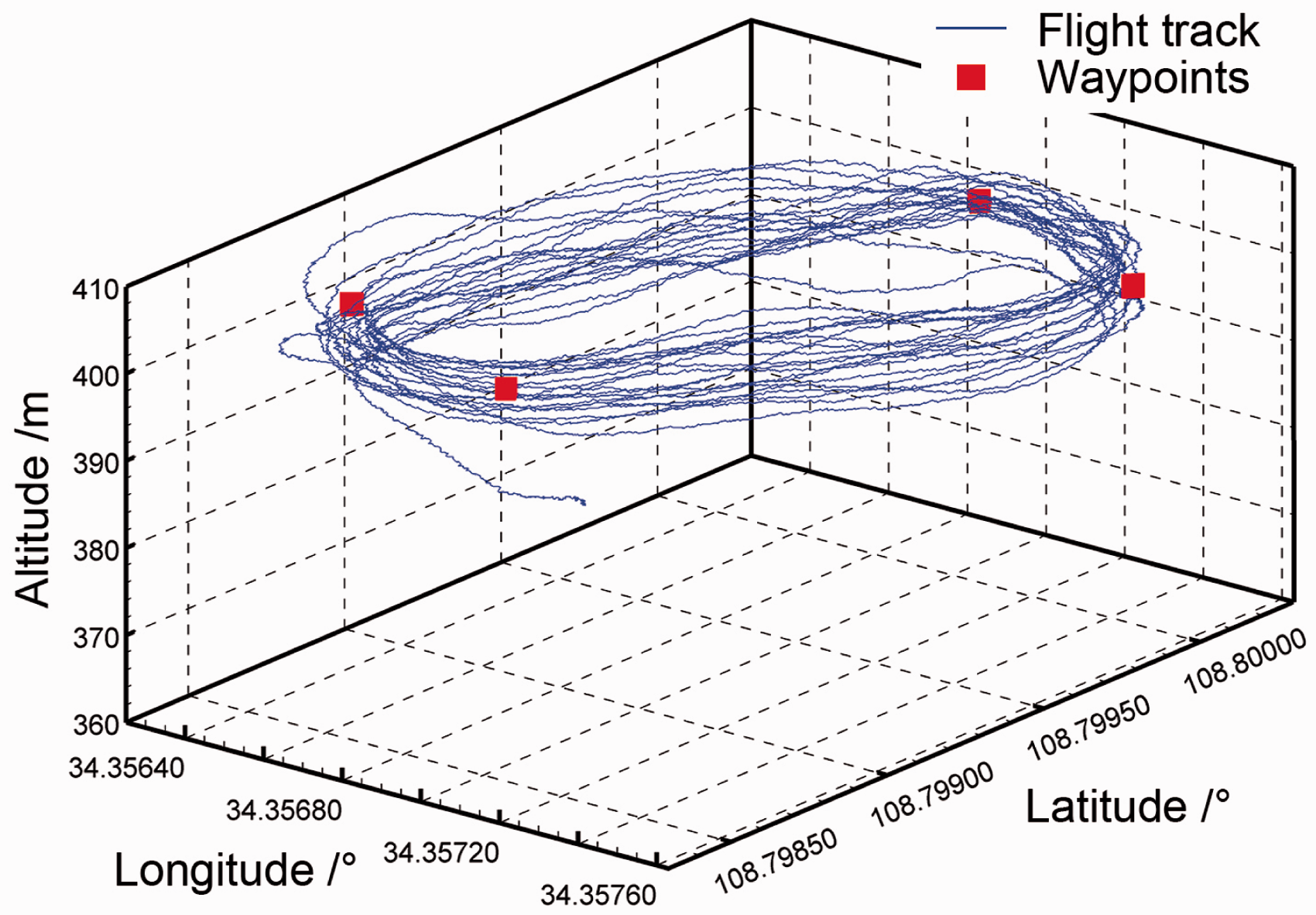
Flight track of Dove in autonomous flight.
As a practical application for surveillance, field tests of Dove were also carried out on different occasions to examine the quality of video. As shown in Figure 21, pictures captured by the on-board camera were very clear and recognizable, thanks to the image processing software running on the ground station computer in real time, most of the image oscillating issues induced by flapping flight were eliminated, the software plays an essential role to make it round off the research program.

Video captured by onboard camera.
The camera's photoreceptor is OV7725, whose spatial resolution is related to the flight altitude as Table 3.
Spatial resolution of camera.

Flapping flight can cause some image oscillating. The flow chart of image processing software is shown in Figure 22.

The flow chart of image processing software.
5. Conclusion
The primary object of the research was to design an FWMAV with adequate loading capacities and the associated micro avionic systems. Evolutionary steps by building prototypes gradually approached the problem, wind tunnel experiments and numerical studies complemented the research process.
It has been demonstrated that the design of Dove’s wing was to take advantage of the flapping flight, numerical approach was carried out to quantitatively determine the design of the flexible structure, and three structure frames were analyzed by the CFD/CSD solver. The wing structure with triangular main frame and longitudinally arranged ribs was choose to be the final design, with which the wing would deflect exactly as the design discipline demanded. Cambered airfoil E387 was applied to the rib, which was able to generate unsymmetrical deformation by cross-section design, additionally raised the lift coefficient of the flapping-wing design.
Flapping mechanism was compatibly designed based on the motor characteristics and the demand of driving the flapping wings. Experiments of the wing’s feasible flapping parameters indicated that there was a specific operating region that the wing could be driven approximately in the same flapping amplitude, when the combinations of attack angle, flapping frequency and flying speed changed. By learning this, the flapping mechanism was designed to be more rational, the combined system of the wings and the flapping mechanism tended to show the highest performance.
On-board avionic systems integrated in Dove were also introduced. One challenge associated with flapping flight was to develop robust control algorithm for such a strongly nonlinear vibrating system. UKF and total energy control were introduced to the flight control system, and flight tests demonstrated that the control algorithm and the hardware itself were extremely successful.
Although the Dove had a certain ability of tasks, there are broad spaces of development remains to be explored. Future work will focus on increasing the efficiency of flapping flight, in other words, increasing the bionic level both in wings and in flapping mechanisms. It makes the FWMAV more agile and looks more like a bird, including the flexibility and flapping manner of the wing. This may be accomplished by highlighting the essence of high-efficient flapping flight, significantly reducing its current mass of avionics, and substantially pushing forward the battery technology.
Footnotes
Declaration of conflicting interests
The author(s) declared no potential conflicts of interest with respect to the research, authorship, and/or publication of this article.
Funding
The author(s) disclosed receipt of the following financial support for the research, authorship, and/or publication of this article: Supported by the National Natural Science Foundation of China, grant 11402208 and U1613227.