
Abstract
Using a camera, a micro aerial vehicle (MAV) can perform visual-based navigation in periods or circumstances when GPS is not available, or when it is partially available. In this context, the monocular simultaneous localization and mapping (SLAM) methods represent an excellent alternative, due to several limitations regarding to the design of the platform, mobility and payload capacity that impose considerable restrictions on the available computational and sensing resources of the MAV. However, the use of monocular vision introduces some technical difficulties as the impossibility of directly recovering the metric scale of the world. In this work, a novel monocular SLAM system with application to MAVs is proposed. The sensory input is taken from a monocular downward facing camera, an ultrasonic range finder and a barometer. The proposed method is based on the theoretical findings obtained from an observability analysis. Experimental results with real data confirm those theoretical findings and show that the proposed method is capable of providing good results with low-cost hardware.
Introduction
The state estimation of vehicle position is a fundamental necessity for any application involving an autonomous micro aerial vehicle (MAV). In outdoor environments, this problem is seemingly solved with on-board global positioning system (GPS) and inertial measurement units (IMU), or with their integrated version, the Inertial Navigation Systems (INS). Contrary, unknown, cluttered and GPS-denied environments still pose a considerable challenge.
While available attitude and heading systems (AHRS) handle well the estimation of the orientation of MAVs, GPS-based position estimation has some drawbacks. Especially, GPS is not a reliable service as its availability can be limited in urban canyons and is completely unavailable in indoor environments. Moreover, even when the GPS signal is available, the problem of position estimation could be not solved for several scenarios. For instance, in Munguia et al., 1 it is shown that the precision of standard GPS could not be enough in order to perform precision maneuvers.
Simultaneous localization and mapping (SLAM) methods can be used for addressing the problem of the state estimation of MAVs. In this case, MAV operates in a priori unknown environment using only on-board sensors to simultaneously build a map of its surroundings which it used to track its position. This means that no external infrastructure (i.e. GPS) is needed in order to localize the vehicle. Many different kinds of sensors can be used for implementing SLAM systems, for instance, laser2,3 sonar,4,5 sound sensors, 6 RFID 7 or computer vision.8–10 The selection of such a sensor technology has a great impact on the algorithm used in SLAM and, depending on the application and other factors, each technology has some strong and weak points.
In the case of MAVs, there exist several limitations regarding to the design of the platform, mobility and payload capacity that impose considerable restrictions on the available computational and sensing resources. The aforementioned issues have motivated that recent works move towards the use of cameras as the primary sensor. Cameras provide a lot of information and are well adapted for embedded systems because they are light, cheap and power-saving.
Using a camera, an MAV can perform visual-based navigation in periods or circumstances when the position sensor is not available, when it is partially available, or when a local navigation application requires high precision. In particular, and compared to another kind of visual configurations (e.g. stereo vision), the use of monocular vision has some advantages in terms of weight, space, power-saving, or scalability. On the other hand, it introduces some technical difficulties as the challenge of directly recovering the metric scale of the world. 9
Related work
In the case of monocular vision with application to aerial vehicles, different approaches have been followed for estimating the state of the vehicle without the aid of a GPS system. In Mirzaei and Roumeliotis, 11 a monocular SLAM system is proposed where the scale factor is retrieved from a feature pattern with known dimensions. In the case of monocular SLAM systems proposed in Weiss et al. 12 and Foster et al., 13 the map is initially set by hand, by aligning the first estimates with the ground-truth in order to get the scale of the environment. In Celik and Somani, 14 the problem of the scale recovering is addressed for environments formed by corridors, like those commonly found in office buildings. In this case, several assumptions are made about the structure of the environment, like the flatness of the floor. Also, it is assumed that the relative altitude of the MAV respect the floor is known by the use of an ultrasonic range sensor, as well as the distance from the MAV to the wall of the corridor. Another approach for recovering the metric scale consists in integrating inertial measurements from an IMU (accelerometer and gyroscopes). In particular, in Nutzi et al., 15 the scale is explicitly considered in the system state, and it is estimated through an Extended Kalman Filter (EKF). The filter makes use of an innovation error defined by the difference between the unscaled acceleration (obtained from the monocular vision), and the measured acceleration in the vertical axis (obtained from the IMU). In Wang et al., 16 the same approach is also followed. The potential problem with this kind of approach has to do with the fact that the acceleration obtained from an IMU has a dynamic bias which is difficult to estimate. This bias introduces at the same time a bias in the estimated scale. Moreover, in this kind of set-up, it is required a precise calibration for the alignment of the camera and the IMU. In Chowdhary et al., 17 an EKF-based method is proposed in order to perform visual odometry with an unmanned aircraft. This method makes use of inertial sensors, a monocular downward facing camera, and a range sensor (sonar altimeter). Unlike vision-based SLAM, there is no mapping process in visual odometry approaches.
Objectives and contributions
In this work, a novel monocular SLAM system with application to MAVs is proposed. The method is intended to be useful for performing visual-based navigation in fully GPS-denied environments or as a backup system in periods where GPS-signal is not available. In order to estimate the state of the vehicle and a map of the environment, the proposed system makes use of: (i) visual information captured from a monocular downward facing camera, (ii) range measurements obtained from an ultrasonic range finder, and (iii) measurements of atmospheric pressure obtained from a barometer.
An observability test is carried out in order to analyze the problem of the recovery of the metric scale. The theoretical findings obtained from this test are used as a basis for developing the proposed system.
Unlike the approaches,15–17 the proposed method does not make use of inertial sensors and thus, there is no need of an extensive pre-calibration routine for aligning the IMU and the camera. In Chowdhary et al., 17 a range finder is used as an altimeter, and therefore it is assumed that all the landmarks lie on a plane (flat terrain assumption). In this work, the range finder is used for computing an approximation of the relative depth of features. Thus, the assumption of a completely flat terrain is considerably relaxed by the assumption of a terrain with soft but continuous changes in altitude.
Moreover, in this work, a barometer is used for incorporating altitude information into the system in order to improve the observability of the metric scale. In certain conditions, the use of the barometer may be sufficient for recovering the metric scale when the ultrasonic range finder is out of its operation range. For instance, in Celik and Somani 14 or in Chowdhary et al., 17 accelerometers are used for recovering the metric scale, but the dynamic error bias of an accelerometer is larger than the error bias of a barometer. 18 Moreover, the barometer is commonly used as augmentation sensor for limiting the error in inertial navigation systems.
Preliminaries
The problem to be addressed will be introduced using a simplified 2-DOF model. It is important to note that this model is representative of the main aspects of the full problem. Later, the proposal will be extended in order to be applied to a three-dimensional context.
Consider the following unconstrained model System parametrization.

Let

Let 
The state of a ith feature yi is defined by
The system state x to be estimated is composed by the camera state xc, and it is augmented with the state yi of every feature contained in the map

When a feature is detected for the first time from a monocular camera (bearing sensor), only information about the ray can be retrieved. In the case of the well-known undelayed inverse depth (UID) EKF-SLAM method proposed in Montiel et al.,
19
new features are incorporated into the system state by assuming an hypothetical initial inverse depth Gaussian prior on
Observability of metric scale
The use of monocular vision introduces some technical challenges. First, depth information is difficult to retrieve in a single frame and hence, robust techniques for recovering the depth of the features are required.20,21 Another challenging aspect of working with monocular sensors has to do with the difficulty of directly recovering the metric scale of the world. Davison et al. 9 stated that if no additional information is used and a single camera is used as the solely source of data to the system, then the map and trajectory can be recovered without metric information.
In this section, the problem of the observability of monocular SLAM systems applied to MAVs is studied. The theoretical results obtained here will be used later as a basis for developing a monocular-based SLAM system capable of recovering the metric scale without need of absolute position measurements as those provided by GPS.
In Civera et al., 22 it is shown that a monocular SLAM system can be initialized with no prior knowledge of scene objects within the context of a dimensionless parametrization of the problem. It is also described how the monocular SLAM state vector can be partitioned into two parts: a dimensionless part, representing up-to-scale scene and camera motion geometry, and an extra metric parameter representing scale.
In our work, in order to make explicit the relevance of the metric scale in monocular SLAM problem, the approach proposed in Civera et al.
22
is followed. In this case, the state vector defined in equation (4) is split into a metric parameter s, unobservable when only angular measurements are available, and a dimensionless map and camera part.

Camera measurements will reduce scene geometry uncertainty, but not the uncertainty in the metric parameter s. The mapping process from the state vector xs to the metric geometry is a non-linear computation process involving the dimensionless geometry and the parameter s

In order to define the system dynamics in terms of the metric parameter s and the dimensionless parameters, equation (6) is substituted into equations (1) to (3), and the system state is augmented with s. Hence, the system dynamics becomes

In the system represented by equation (7), a constant-acceleration camera model is assumed. Also it assumed a rigid scene (map features remain static) and a constant metric scale. The system output equation is


Considering the above aspects, the system state can be simplified by removing the variables related to attitude and heading (which are provided by the AHRS). Therefore, the problem will be focused on the position estimation of the MAV.
Considering the above remarks the system state xs becomes

If n landmarks are measured by the camera, the system output is defined as
A system is defined as observable if the initial state x0, at any initial time t0, can be determined given the state transition and observation models of the system and observations
In Hermann and Krener,
25
it is demonstrated that a non-linear system is locally weakly observable if the observability rank condition rank(

The following result was obtained for the system conformed by the state of equation (10):
The maximum degree of observability was obtained with four landmarks. In this case, dim(xs) = 9, rank(
Now let consider that the measurements of altitude of the MAV camera are becoming available. The additional system output equation ya is

Hence, if n landmarks are measured by the camera, the system output is now defined as

By considering the availability of measurements of altitude, the following results were obtained:
The maximum degree of observability was obtained with only three landmarks, but in this case, the system becomes observable, that is, dim(xs) = 8, rank( The movement of the vehicle on the vertical axis (
Now let consider that instead of altitude readings, the measurements of range are available for a subset of features. The range measurement of ith feature is modeled by an equation of the form

Hence, if n landmarks are measured by the camera Cs, and m range measurements (

Note that in equation (15) only the zero-order Lie Derivative is used for range measurements. Considering the availability of such range measurements the following result was obtained:
Independently of the number of features included into the system state, full observability, dim(xs) =rank(
It is important to note that the purpose of the previous analysis over a simplified 2-DOF model is not to prove (by extension) the full observability of the whole SLAM system, but to show that the metric parameter s representing scale could become observable if measurements of absolute altitude or measurements of range for a subset of features are available. A full observability analysis in 6-DOF should be of great interest for future work.
Method description
Sensor fusion approach
As it has previously seen, the metric scale is difficult to be recovered using monocular vision. On the other hand, it was found that the metric scale can become observable if altitude information is included into the system. As a consequence of this result, altitude measurements obtained from a barometer are incorporated into the system. However, it was also found that if this approach is followed, the observability depends on the movement of the vehicle. These facts mean that the effectiveness of this approach can be compromised in periods where the MAV performs only short and small movements.
Another interesting theoretical result has to do with the fact that the system becomes observable with the inclusion of a single measurement of depth of a map feature. In order to take advantage of this result for improving the robustness of the proposed method, a technique for incorporating approximate information about the depth of features is proposed. For the foregoing purpose, an ultrasonic range finder is also incorporated into the system.
Aerial platform
As shown in Figure 2, the platform considered in this work is a quadrotor moving freely in any direction in Aerial platform and coordinate systems.
The quadrotor is equipped with a barometer for measuring atmospheric pressure. The monocular camera is mounted over a servo-controlled gimbal. The gimbal is configured in order to counteract the changes in attitude of the quadcopter, and therefore it stabilizes the orientation of the camera toward the ground. Besides the camera, an ultrasonic range finder is also mounted over the servo-controlled gimbal. The ultrasonic sensor is aligned in parallel to the optical axis of the camera (see Figure 2). In this work, it is assumed that a possible misalignment of the camera respect to the ultrasonic sensor is negligible if it is compared with other inherent constraints of the ultrasonic sensor. In this case, it is assumed that the lack of a fine calibration is taken into account by means of an uncertainty parameter used for modeling the error in sensor measurements.
The proposed method is mainly intended for local autonomous vehicle navigation. In this case, the local tangent frame is used as the navigation reference frame. Thus, the initial position of the vehicle defines the origin of the navigation coordinates frame. The navigation system follows the NED (North, East, Down) convention. The magnitudes expressed in the navigation and camera frame are denoted respectively by the superscripts N , and C . All the coordinate systems are right-handed defined. In this work, it is assumed that the location of the origin of the camera frame respect to other elements of the quadcopter (e.g. barometer) is known and determined. Hence, the position of the origin of the vehicle can be computed from the estimated location of the camera.
Sensor measurement models
Visual measurements
A standard monocular camera is considered to be mounted aboard the quadrotor. In this case, a central-projection camera model is assumed. The image plane is located in front of the camera’s origin where a non-inverted image is formed. The camera frame C is right-handed with the z-axis pointing to the field of view.
The

Let u and v be the coordinates of the image point p expressed in pixel units, and

Let pC be the same 3D point pN, but expressed in the camera frame
C
by
Inversely, a directional vector

Vector hC points from the camera optical center position to the 3D point location. The vector hC can be expressed in the navigation frame by
The distortion caused by the camera lens is considered through the model described in Bouguet.
27
In this case, radial and tangential distortions are considered. Using the former model (and its inverse form), undistorted pixel coordinates (u, v) can be obtained from
Range measurements
An ultrasonic range finder is used, whenever is possible, in order to obtain approximate information about the range (depth) of features. The idea is to define an image region where visual features lying inside could be associated with a range provided by the ultrasonic sensor. The image region is a function of the range measured by the sensor as well as its beam pattern.
Every time that a range reading, provided by the ultrasonic sensor, is available, it will associated with the next camera frame. Due to the operating frequency of ultrasonic range sensors, typically lower (3–4 Hz) than the frame rate of cameras, only a subset of the frames will have an associated range.
The beam pattern of the ultrasonic range finder is modeled by an elliptic paraboloid (see Figure 3) satisfying: The ultrasonic range finder is used for estimating the approximate depth of visual features lying in its beam pattern (left). An elliptic paraboloid is used as a simple model of the actual beam pattern of the ultrasonic range finder (right).
First, let zr be the range measured by the ultrasonic sensor. Then, a circle The size of the terrain region detected by the ultrasonic range finder is a function of the beam pattern of the sensor and the flight altitude of the MAV. Frame captured at 7 m of altitude (left). Frame captured at 
A 3D point located at

Let hN be the directional vector pointing from the camera to the location of the 3D point (see the related equation (18)), and let
In other related methods, the range measured by the telemeter is associated (directly or indirectly) with all the visual features seen by the camera.
17
In the proposed method, the range is associated only with the visual features lying inside of the region covered by the beam pattern of the ultrasonic sensor. Hence, it is assumed that only the portion of the ground detected by the ultrasonic sensor is approximately planar. This is important because the assumption of a quasi-flat terrain is locally restricted to a circular central image region and not the global image itself (see Figure 5). In this manner, the flat-terrain assumption could be relaxed if the whole terrain is supposed to be composed of several connected sub-regions with small but continuous changes in altitude between them.
Initialization of new map features: Camera frame with an associated range measurement (left plot). Zenithal view (middle plot) and sectional view (right plot) of the estimates. The ellipses indicate the initial uncertainty region of a new feature 3D location. Note that the visual features lying inside of the circular image region, determining the portion of the terrain detected by the ultrasonic range finder, are initialized as new map features with a smaller initial uncertainty in depth.
Altitude measurements
Measurements of altitude can be inferred from measurements of atmospheric pressure. The proposed method is mainly intended for local autonomous vehicle navigation. Hence, the altitude or height of the MAV above a local ground location is computed from the change in pressure between the ground and the altitude of interest. The following formula can be used for computing the local altitude za from a barometer

EKF-SLAM
The system state to be estimated is

Let
Map features are defined by

Let

Let
System prediction
The system state x is taken a step forward by the following discrete model
At every step, it is assumed that there is an unknown linear velocity with acceleration zero-mean and known-covariance Gaussian processes σa, producing an impulse of linear velocity:
Note that in this work, for simplicity, a Gaussian random process is used for propagating the velocity of the vehicle. However, a feasible alternative could be the use of the dynamical model of the aircraft instead of the Gaussian random process. However, this approach commonly requires having a considerable knowledge about the specific physics of each aerial vehicle where the proposed method could be applied.
Initialization of map features
The initialization process of new map features is carried out using frames with an associated range zr (see subsection Range measurements). A random search is conducted over the image in order to detect new visual features in regions without them.
In this work, the detector proposed in Rosten and Drummond 30 is used for detecting new visual features, but any other detector with good performance could be used instead.
The coordinates of a ith new visual feature are defined by (ui, vi).
Any new feature

The new covariance matrix Pnew is computed by

Measurement of map features
In order to update the filter with the re-observation of map features the following approach is followed:
Each feature yi does model a 3D point pN located at

If the visual feature lies outside the circle, it is assumed that the landmark is out of range of the ultrasonic range finder and hence, the visual measurement model On the other hand, if the visual feature lies inside the circle, it is assumed that the landmark is on the range of the ultrasonic range finder. Hence, depth information is incorporated through the measurement model
Altitude updates
Whenever is possible, information about the relative altitude of the MAV is incorporated to the filter using the standard update equations.
The measurement model of altitude
Experimental results
To perform the experiments with real equipment, a custom-built quadrotor is used (Figure 6). The vehicle is equipped with an Ardupilot unit as flight controller,
31
a Radio Telemetry 3DR 915 MHz, a DX201 DPS camera with wide angle lens, a 5.8-GHz video transmitter and an ultrasonic range finder XL-MaxSonar-EZ0. The flight controller has a built-in barometer. The camera is mounted over a very low-cost gimbal which is servo-controlled by standard servomotors.
A custom-built quadrotor was used for performing the experiments with real data.
In experiments, the quadrotor has been manually radio-controlled. A custom-built C++ application running over a laptop has been used for capturing data from the vehicle received via MAVLINK protocol, 32 as well as capturing the digitalized video signal transmitted from the vehicle. The data obtained from the sensors (barometer and ultrasonic sensor) as well as the frames captured by the camera were synchronized and stored in a dataset. The frames with a resolution of 320 × 240 pixels, in gray scale, were captured at 26 fps. A MATLAB® implementation of the proposed method was executed offline over the dataset, in order to estimate the flight trajectory and the map of the environment.
In experiments, in order to evaluate the performance of the proposed method, an independent trajectory computed by a perspective on 4-point (P4P) technique was used. For computing the P4P trajectory, four marks were placed in the floor, forming a square of known dimensions (see Figure 4). Then, a perspective on 4-point (P4P) technique 33 was applied to each frame in order to compute the relative position of the camera with respect to this known reference. It is important to note that the trajectory obtained by means of this technique should not be considered as a perfect reference of ground-truth. However, this approach was very helpful to have a fully independent reference of flight for evaluation purposes.
Two different flight trajectories (a and b) were performed over two different outdoor test fields consisting in urban parks. Figure 7 shows the trajectory and map for both cases, estimated by means of the proposed method. The upper plots show a 3D view of maps and estimated trajectories. The middle plots show the zenithal (x-y) view of maps and estimated trajectories. The lower plots show the sectional (z-x/y) view of maps and estimated trajectories. In this case, a good concordance between the P4P trajectory and the one computed with the proposed method was found.
Flight trajectory and map estimated with the proposed method. For comparison purposes the flight trajectory was also computed in an independent manner using a P4P technique.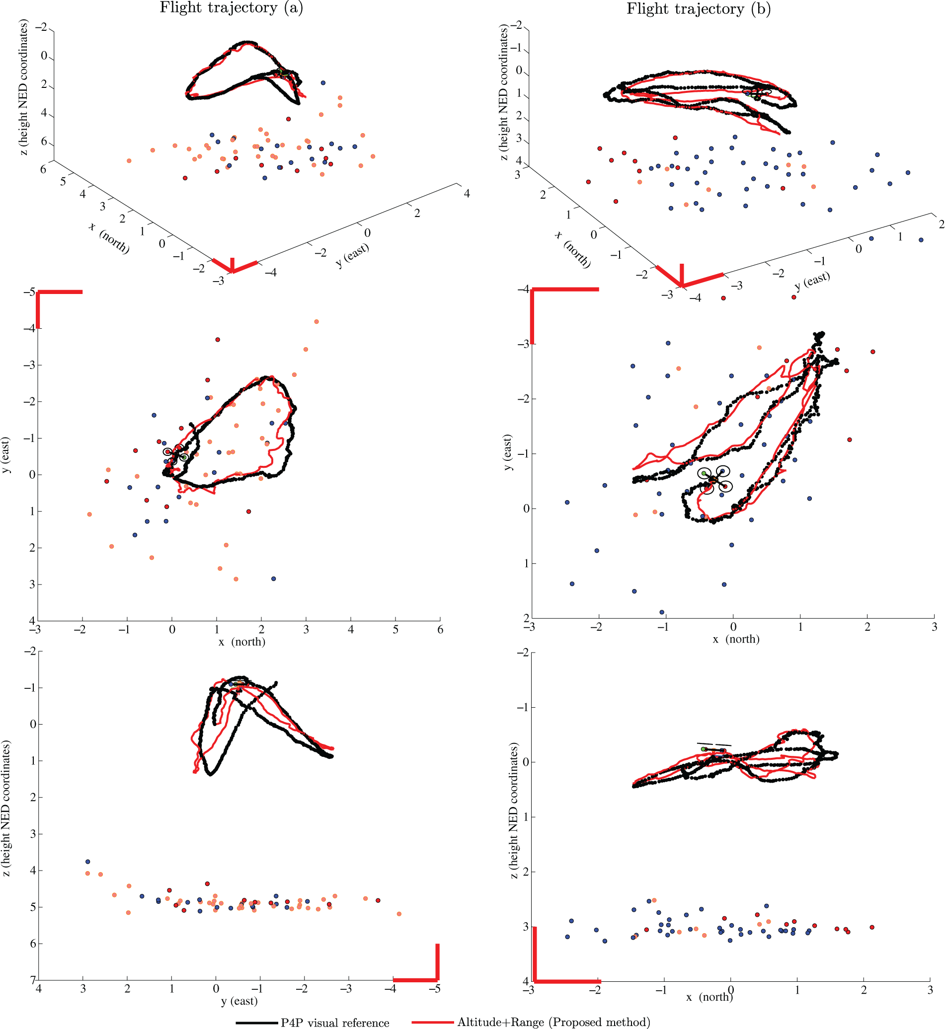
A comparative study has been performed in order to gain more insight about the performance of the proposed method. For this purpose, the same flight trajectories were also computed under other two different conditions: (i) using only visual information, (ii) using visual and altitude information.
In the first case (i), the undelayed inverse depth method (UID)
19
was used for initializing the visual features. Because no extra aid of any kind of sensory information is used, the metric scale of the estimates depends only on the initial hypotheses of inverse depth ρ0, which is a parameter to be manually set. Considering that the flights of the MAV were performed at low altitude, a value of initial depth
Figure 8 shows the progression over time for each estimated trajectory by: (i) the proposed method (altitude + range), (ii) UID method, (iii) altitude + UID, and (iv) P4P visual reference. A separate plot for each coordinate North, East, and Down (x, y, z) is presented. In this comparison study, the results were obtained averaging 10 executions of each method. It is important to note that those averages are computed because the methods are not deterministic since the search and detection of new visual features points is conducted in a random manner over the images.
Estimated positions expressed in each coordinate north, east, and down (x, y, z).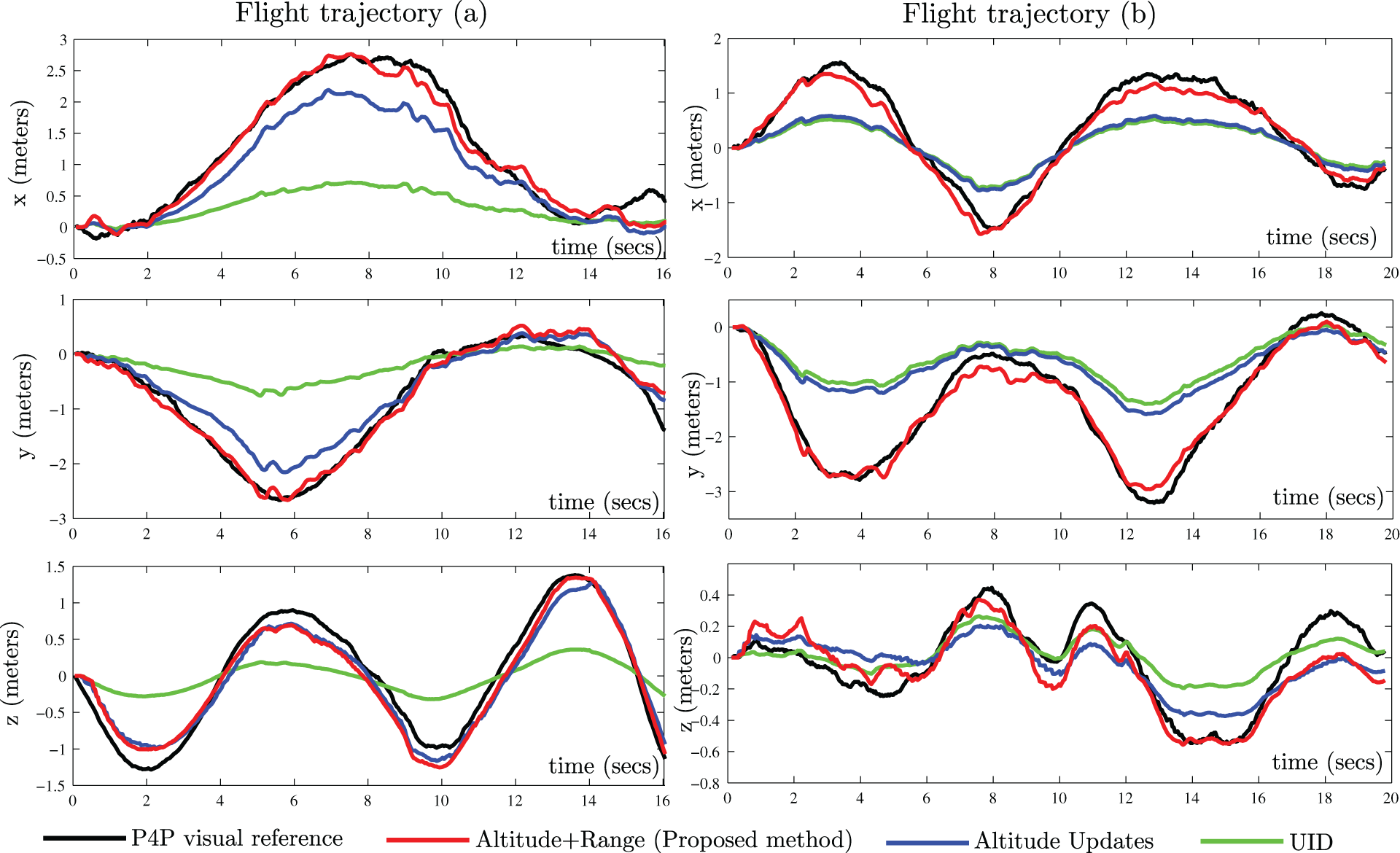
Results for flight trajectories ‘a’ and ‘b’.

UID: undelayed inverse depth; NIF: number of the features initialized into the system state; NDF: number of features deleted from the system state; FPF: number of features been tracked at each frame; TTE: total time of execution; aMAE: average mean absolute error.
From these results it can be concluded that
For flight (a): Taking the UID trajectory as an unscaled reference, it can be appreciated that the inclusion of altitude measurements (A + UID) can be useful by itself in order to recover the metric scale of the estimates. Note that for this flight, there is a considerable variation in altitude along the trajectory. Even though an acceptable result was obtained with the (A + UID) method, the result obtained with the proposed method (A + R) was considerable better. For flight (b): The solely inclusion of altitude measurements (A + UID) contributes little in terms of improvements of the recovery of the metric scale. This result can be explained because for this flight there is little variation in altitude along the trajectory, (especially at the beginning). On the other hand, with the proposed method (A + R), the actual trajectory was also successfully recovered. In both flights, with the proposed method (A + R) fewer features were initialized into the system state than the other approaches, because features are initialized only in frames where range measurements are available. It is advantageous if the system performs well with few features because a smaller computational cost is need.
It is interesting to note that the theoretical findings presented in section Observability of metric scale are well supported by the empirical results obtained with real data. Also, it is shown that the proposed method is capable of working with the data obtained from low-cost sensors, in order to estimate the flight trajectory of an MAV.
Conclusions
Using monocular SLAM, an MAV can navigate relying on visual information in environments where GPS is not available. Compared with other approaches, the monocular vision has advantages in terms of weight, space, power-saving, and scalability, but it introduces some technical difficulties as the impossibility of directly recovering the metric scale of the world.
In this work, a theoretical analysis has been carried out in order to study the observability of a monocular SLAM system applied to an MAV. According to the theoretical findings, under certain conditions the metric scale can become observable by the inclusion of altitude measurements into the system. Also, it was found that depth measurement of even a single landmark can improve the observability of the system.
Based on the theoretical findings, a novel monocular SLAM system is proposed. In this case, for recovering the metric scale of the world, two extra sources of sensory information have been considered: (i) an ultrasonic range finder is used for computing the approximate depth of features whenever is possible and (ii) a barometer is used for updating the system with information about the local altitude of the MAV.
In order to validate the proposal, experimental results have been obtained using real data acquired by sensors onboard of a custom-built quadrotor. Based on these results, it is shown that by means of the proposed system, the MAV is able to recover its flight trajectory as well as a map of the environment using only those sensors. The proposed method is robust enough to be implemented with low-cost hardware.
Footnotes
Declaration of conflicting interests
The author(s) declared no potential conflicts of interest with respect to the research, authorship, and/or publication of this article.
Funding
The author(s) disclosed receipt of the following financial support for the research, authorship, and/or publication of this article: This research has been funded by Spanish Science ministry project DPI2016-78957-R (ColRobTransp).