
Abstract
In this article, we propose a distributed and collaborative monocular simultaneous localization and mapping system for the multi-robot system in large-scale environments, where monocular vision is the only exteroceptive sensor. Each robot estimates its pose and reconstructs the environment simultaneously using the same monocular simultaneous localization and mapping algorithm. Meanwhile, they share the results of their incremental maps by streaming keyframes through the robot operating system messages and the wireless network. Subsequently, each robot in the group can obtain the global map with high efficiency. To build the collaborative simultaneous localization and mapping architecture, two novel approaches are proposed. One is a robust relocalization method based on active loop closure, and the other is a vision-based multi-robot relative pose estimating and map merging method. The former is used to solve the problem of tracking failures when robots carry out long-term monocular simultaneous localization and mapping in large-scale environments, while the latter uses the appearance-based place recognition method to determine multi-robot relative poses and build the large-scale global map by merging each robot’s local map. Both KITTI data set and our own data set acquired by a handheld camera are used to evaluate the proposed system. Experimental results show that the proposed distributed multi-robot collaborative monocular simultaneous localization and mapping system can be used in both indoor small-scale and outdoor large-scale environments.
Introduction
As the monocular camera is much cheaper, physically smaller and lower powered than other vision systems, for example, stereo and RGB-D cameras, it has been widely applied in the fields of computer vision and robotics. The state-of-the-art monocular simultaneous localization and mapping (SLAM) algorithms have achieved remarkable performance in rich featured, static indoor environments. However, when it moves to multi-robot platforms carrying out long-term SLAM in large-scale environments, there are still many challenges to be addressed. The first of all is the tracking failure problem. Since it is difficult to calculate the accurate depth of observed features using only one camera, most existing monocular SLAM systems are less robust than those based on stereo or RGB-D cameras.
When tracking failure happens, the most effective solution is to add an image-to-map relocalization module, because a large amount of measurements in the map can be used to mitigate the side effect of outliers and higher accuracy can be achieved in pose estimation. 1 However, most of the image-to-map approaches are resource-consuming and normally designed for small workplace or indoor scenarios. 1 –3 They are obviously inapplicable for mobile robots to perform long-term tasks. Inspired by Strasdat et al. 4 and Mur-Artal et al., 5 our system only performs feature matching in a local map when the tracking fails, so the computational complexity is up-bounded. Thus, real-time relocalization can be realized in relative larger environments.
After the relocalization, the drift of SLAM may increase, since during the tracking failure period, the robot is not able to collect enough information to accurately localize itself and build the map. It is well known that loop closure can effectively eliminate the accumulated error. However, most current research only focus on how to detect and close a loop passively but not to control robots to actively create loop closures to correct the SLAM drift. In this article, we propose an active loop closure approach, which uses the information of the robot/camera pose obtained from the relocalization to navigate robots finding a loop actively and, therefore, eliminate the accumulated drift.
Another problem of robots carrying out large-scale SLAM is that the computing capacities of a single robot are normally limited. Naturally, we think of using a multi-robot system to solve this problem. A multi-robot system allows parallel execution of tasks, and, in addition, is more efficient and robust compared against a single-robot system. Considering a scenario of employing a multi-robot team to map a large unknown environment, the task can be divided among all the team members who can collaboratively build a global map to reduce the overall execution time. In a group of robots, each robot should not only rely on its own information but also the information provided by the others. This is not an easy task since the robots in general do not have any prior information about each other’s location. To allow the robots working cooperatively, relative pose estimation and map merging are two fundamental issues.
To calculate the relative pose of the robots, relative localization methods impose the least limitation on both the motion of the robots and the prior information. 6 In addition, this method can realize the merging of local maps without large overlaps. In this article, a cooperative appearance-based place recognition method is employed to enable the robots to identify similar scenes in their visual perception and then compute their relative poses. The similar scenes are identified by performing image-to-image place matching, which is usually employed for loop closure in single-robot SLAM.
The main contributions of our work can be concluded as follows: An image-to-map relocalization method based on local map is proposed, which limits the calculation burden and realizes the unvisited place relocalization in large-scale scenes. A robust relocalization system based on active loop closure is proposed, where the pose information obtained from the latest relocalization is utilized to navigate the robot to find a loop actively and in turn eliminate the drift caused by the tracking failure. A distributed multi-robot collaborative SLAM based on the robust monocular SLAM is proposed, by which a team of robots can cooperatively map the large-scale environment with high efficiency. A relative pose calculation and map merging method is proposed, by which the multi-robot collaborative SLAM can be realized without any prior knowledge and large map overlaps.
Related work
Monocular SLAM
Monocular SLAM was initially solved by filtering, 7 and now it has been developed into two main branches: feature-based approaches and direct approaches.
Feature-based approaches
These methods include two steps: features are first extracted from the images, and then the robot pose is calculated and the environment is mapped based on these features. Early versions of these approaches are based on filters, 7,8 using all the measurements to update the probability distributions of features and poses, which are less accurate and can only be used in small-scale scenes. In order to better realize modern applications, feature-based monocular SLAM methods are now mostly based on keyframes and bundle adjustment (e.g. ORB-SLAM 5 ), which can have high accuracy and low computation cost.
Direct approaches
Direct methods can achieve high accuracy and robustness by optimizing the geometry directly on the image intensities. 9 –11 However, either some of the direct methods mainly focus on visual localization (e.g. DSO 11 ), or some others’ maps are too dense to be used for outdoor large-scale multi-robot collaborative mapping system (e.g. LSD-SLAM 9 and DTAM 10 ). Considering the limited bandwidth of robots’ communication, we, therefore, choose the feature-based ORB-SLAM as the implementation basis, which has a lightweight map representation and, meanwhile, can also achieve high accuracy and robustness after adding the proposed relocalization module.
Relocalization
The relocalization problem can be traced back to global self-localization in given maps and was first realized by Dellaert et al. 12 With robots gradually applied to real scenes, the relocalization became a tracking recovery problem, and three types of approaches were proposed 13 : map-to-map, image-to-image and image-to-map.
Map-to-map
It was first implemented by Clemente et al. 14 They found matches between landmarks in two submaps, which are very complex and time-consuming. Also, because the sparse map built by monocular SLAM does not always provide enough mappoints, this method is less accurate and unreliable for monocular SLAM.
Image-to-image
With the monocular SLAM developed from the initial filtering approaches to keyframe-based approaches, the image-to-image method has been explored rapidly. It was first realized by Reitmayr and Drummond 15 and Klein and Murray. 16 Then, Sivic and Zisserman 17 proposed bag of words (BoWs) using visual words for place recognition, which was widely used in the relocalization and loop closure for its high accuracy. For example, Eade and Drummond 18 used BoW with SIFT 19 to determine the current submap. Cummins and Newman 20 used it with SURF 21 to achieve high robustness to perceptual aliasing. Mur-Artal and Tardós 22 used it with ORB 23 and built the well-known ORB-SLAM. 5 Although it has become popular to use image-to-image method in the relocalization, this method is only effective when robots run in the previously visited places where keyframes exist. This assumption does not hold for mobile robots when running in large-scale environments exploring unvisited places.
Image-to-map
This problem can be solved by image-to-map approaches which were first proposed by Pupilli and Calway. 24 They built a short-distance tracking recovery system by exploring multiple hypotheses with a particle filter. To realize a global image-to-map approach, Se et al. 25 used SIFT features in two-dimensional (2D) scenario. Williams et al. proposed a three-dimensional (3D) relocalization based on a filtering approach and feature recognition. 1 They published a survey comparing different types of relocalization and loop closing approaches. 13 According to the survey, to deal with the relocalization in monocular SLAM, image-to-map approaches perform best for higher accuracy, speed and robustness. Afterwards, Straub et al. 3 used locality sensitive hashing (LSH) 26 to speed up the nearest neighbour searching. Feng et al. 2 improved this work using online learning process to construct the hash key, which made the relocalization more robust.
Active loop closure
Loop closure is another important problem in SLAM, which can correct the accumulated error of the map and the robot trajectory. Traditional loop closure methods are passive and normally performed by human or on the pre-planned trajectories. However, robots’ motions can strongly affect the SLAM performance, which has become a hot topic named active SLAM coined by Feder et al. 27 Active SLAM can be described as controlling the robot’s motion to minimize the uncertainty of its map and localization. Our system introduces this idea into the relocalization, which aims to correct the drift and finally achieve higher accuracy and robustness.
Multi-robot collaborative monocular SLAM
There are many solutions for the single-robot SLAM, but when it moves to multiple robots platforms, another layer of challenges will be introduced. Especially for the monocular SLAM, the estimation of relative poses and the map merging problems are very challenging, as the monocular vision cannot obtain the accurate depth information and the scales of robots’ maps are usually different from each other.
Relative poses estimation and map merging
One of the most important steps to realize multi-robot collaborative SLAM based on monocular vision is to calculate the relative poses of the robots and then consolidate their local maps into a large-scale global map. According to Rone and Ben-Tzvi, 28 the proposed approaches can be classified into the following four categories.
Known initial poses
In this case, the initial poses of the robots are known, and thus the relative poses of the robots can be determined at any time. The assumption of having knowledge of the initial poses limits the application of multi-robot SLAM.
Rendezvous
In the rendezvous method, 29 robots meet at a point. At the meeting point, the relative poses can be calculated through the line-of-sight measurements. Once the relative poses are known, maps can be merged. However, this approach will bring another challenge, which is the coordination for the meeting.
Relative localization
A more advanced form of the rendezvous is the relative localization. In this method, one robot localizes other robots in its own map 30 ; thus, without rendezvous, the relative poses of the robots can be determined. 31
Based on overlaps
In this approach, the overlaps between the maps are used to calculate the relative transformation between the maps and the poses. 32 The challenge of this approach is finding the overlaps; however, this method does not need rendezvous and robots can be out of teammates’ maps at any time.
Multi-robot collaborative monocular SLAM
Recently, most of multi-robot SLAM algorithms use combinations of various types of sensors such as laser range finder and IMU. 33 –36 Very little work based on monocular vision has been done, since it may cause many problems such as the lack of depth, different scales and scale drift. It first appeared as the multi-robot visual localization problem proposed by Fox et al. 37 and Martinelli et al. 38 or multi-robot mapping problem proposed by Vidal-Calleja et al. 39 They proved that the overall localization accuracy and mapping efficiency of cooperative multi-robot SLAM are much higher than that of single-robot SLAM. Later, Kaess and Dellaert 40 realized a system of multi-camera structure from motion (SfM), while Sola et al. 41 realized a multi-camera SLAM system, both of which are the rudimentary form of multi-robot monocular SLAM. Doitsidis et al. 42 presented a two-step centralized algorithm for surveillance coverage for multiple micro aerial vehicles (MAVs), but the initial poses of the robots are assumed to be known. Forster et al. 43 first proposed a real-time collaborative monocular SLAM algorithm called collaborative SfM (CSfM). In CSfM, each MAV generates a six degree of freedom (DOF) estimation of its own pose using monocular visual odometry. Features of selected keyframes are sent to a centralized ground station where a global map is generated when the overlap between the maps is detected. Based on CSfM, Chebrolu et al. 44 presented a similar framework for multi-robot SLAM, but each robot is capable of performing complete SLAM individually using full image information instead of using only features. In addition, a feedback mechanism is used to correct the local estimates continuously. Similar to them, Schmuck 45 recently proposed a multiple MAVs collaborative monocular SLAM, which employs MAVs as agents to independently explore the environment running limited-memory SLAM onboard.
The proposed robust relocalization method is based on our previous work, 46,47 and we give a more exhaustive explanation in this article. Our work is similar to these works, 1 –3 for using the image-to-map relocalization method. However, their works are based on pre-trained classifiers or hash methods, which need extra time to train the classifiers and can only be used in small workplaces or indoor scenarios. Differently, based on a local map and ORB features, our work can be used in outdoor large-scale environments with higher accuracy and efficiency. The local map we used is similar to that of Strasdat et al. 4 and ORB-SLAM, 5 while our method can be applied in unvisited environments. Stachniss et al. 48 and Rahimi et al. 49 also use active loop closure to reduce the drift. Different from them, we here propose to combine the relocalization and active loop closure, which can simultaneously raise the accuracy of the relocalization result and solve the well-known ‘when to use’ problem in active SLAM. The combination system can overcome the shortcomings of both parts and achieve a good performance as an integrated system.
Based on the proposed robust monocular SLAM, we realize a novel multi-robot collaborative SLAM system. The proposed multi-robot SLAM is different from these works, 37 –39,42 because we do not need the initial relative poses of the robots and not rely on the maps to determine the relative poses. We utilize a place recognition method based on image-to-image feature matching to identify similar scenes and then calculate the relative poses. Furthermore, different to the MAV-based server-agent like centralized architectures, 43 –45 our system is fully distributed, which has higher reliability and better overall performance when fulfilling an outdoor large-scale SLAM task.
Robust monocular SLAM
The overview of the robust monocular SLAM
The proposed monocular SLAM uses an active loop closure-based relocalization system to make itself more robust, which can detect and recover from tracking failures automatically even in previously unvisited areas where no keyframe exists. The proposed system is based on the state-of-the-art real-time monocular SLAM, ORB-SLAM, 5 which has a lightweight representation of the environmental map based on sparse feature points. This makes it possible for multiple robots to share their maps via wireless communication. Furthermore, after adding the proposed relocalization module, the improved monocular SLAM can also be very robust and accurate when used in outdoor environments. Figure 1 demonstrates the structure of the proposed robust monocular SLAM, which is composed of five parts: tracking, loop closing, local mapping, relocalization and active loop closure. The first three modules form the paradigm of the current appearance-based monocular SLAM. Following the original ORB-SLAM, the tracking thread localizes the camera in every frame and decides when to insert a new keyframe; the local mapping thread processes new keyframes and maintains the local map; and the loop closing thread searches loops and corrects the accumulated drift. The details of the monocular SLAM implementation are introduced in ‘Experiments’ section. When the tracking fails, the proposed robust monocular SLAM will employ the relocalization module on each incoming frame, which is explained in detail in ‘Relocalization module’ section. To solve the drift problem caused by tracking failures, the proposed system can actively create loop closure to reduce the drift through path planning and robot movements, which is explained in ‘Active loop closure module’ section.

The overview of the proposed robust relocalization system based on active loop closure. It includes five main parts: tracking, local mapping, loop closing, relocalization and active loop closure.
Relocalization module
In our relocalization module, the image-to-map method is used based on local maps. Similar to most image-to-map approaches, we estimate a six-dimensional pose from 2D image to 3D maps, but the difference is that our method only uses the simplest exhaustive nearest neighbour searching method to establish the associations between the descriptors extracted from the current frame and the mappoints stored in the local map, while most other methods are classifier-based, which are time-consuming and sometimes inaccurate.
Our method benefits from the ORB features and the local map, as ORB features allow us to directly compute the hamming distance between the respective binary descriptors, very efficiently using low-level hardware operations; and the local map helps us reduce the searching space in an efficient way. Once the tracking fails, the proposed relocalization method will try to recover the tracking process by finding the robot/camera pose in every incoming frame which is summarized in algorithm 1. The steps of the proposed relocalization method are described as follows.
Relocalization algorithm.


Feature extracting
The first step is to extract ORB features in the current frame (line 3 of algorithm 1). Like ORB-SLAM, we use the image pyramid of eight scale levels with a scale factor of 1.2 and detect FAST keypoints in each level to make the features invariant to the scale in a certain degree. Furthermore, since ORB feature 23 is made up of oriented FAST corner and rotated BRIEF descriptor, it can be extracted very fast and has a certain level of rotational invariance. Therefore, we extract ORB features in every incoming frame and utilize them in every module of our SLAM system, which makes it possible to be used in large-scale environments.
Descriptor matching
The second step is to find the matches between the extracted features and mappoints stored in the local map (line 4 of algorithm 1). Mappoints form the 3D reconstruction of the environment. They are defined by two coordinates
Pose estimating
The third step is to estimate the robot/camera pose from the set of 2D to 3D matches by solving a PnP problem using an RANSAC scheme (line 6 of algorithm 1). In practice, we use EPnP
51
to randomly select four non-coplanar points to calculate the camera pose and then use RANSAC to iteratively verify the estimated camera pose. Once the number of the inliers exceeds a certain threshold, we accept this pose as the new camera pose and recover the SLAM process. Specifically, let the reference points, that is, the n points whose 3D coordinates are known in the world coordinate system, be

where

The unknown parameters of this linear system are the 12 control point coordinates and the n projective parameters. The last row of equation (2) implies that


Let

The solution, therefore, belongs to the null space or kernel of
where the set
Let the transformation be

To calculate the rotation matrix

Then, we calculate the homography matrix

The rotation matrix

Pose optimizing
After estimating a raw camera pose, we use the Levenberg–Marquardt-based bundle adjustment method to refine the pose (line 7 of algorithm 1). In our image-to-map relocalization module, the actual optimization objects are the reprojection errors, and we use the famous optimization library g2o
52
to implement this method. Taking two views as an example, also let the n points whose 3D coordinates are known in the world coordinate system, be
where

where
Thus, we sum the reprojection errors and build a least square problem

By minimizing the sum of reprojection errors, we can find a more accurate camera pose
Active loop closure module
As discussed above, fast and long-distance tracking recovery can be achieved using the proposed relocalization module. However, because of the information missing during the tracking failure, it is inevitable to have a larger drift after the relocalization. We, therefore, employ an active loop closure module to reduce the drift after the relocalization and acquire more accurate maps, which is summarized in algorithm 2. Once relocalizing successfully, the system will enable the active loop closure module which includes three steps.
Active loop closure algorithm.

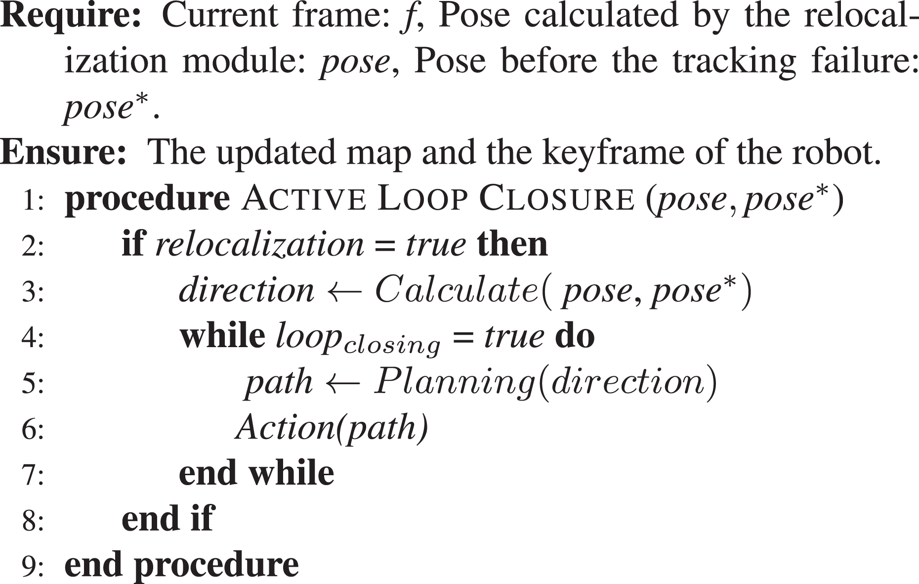
Direction computing
We first calculate the robots movement direction (line 3 of algorithm 2). After the relocalization, we get an optimized pose and a camera pose * stored in the last keyframe before the tracking failure. Their absolute transformations in SE(3) are

where for simplicity, we assume the scale factor to be 1, which does not affect the calculation of the direction. We then compute the relative transformation
where
In this article, we only consider the case that robots conduct the relocalization when travelling forwards into unvisited environments, so the camera’s orientation is almost constant. We, therefore, only take the translation into consideration and compute the direction as follows

Path planning
The second step is to plan a path using the computed direction to realize a loop closure (line 5 of algorithm 2). In fact, any path-planning algorithm which can find a loop between the current pose and the last pose
* based on the calculated direction can be used in our system. It is worth mentioning that only loop closure can eliminate the accumulated error and the scale drift. Other path-planning algorithms cannot deal with this situation even thought they can find paths and re-collect the missing environment information. For example, it is not a best solution for the robot just moving backwards a few meters to revisit previously seen areas, because the mappoints and the camera poses stored in each node/keyframe are consistent. Here, we give a simple example of using the calculated direction and the tracking failure distance to realize the active loop closure. Assuming the robot moving forwards into unvisited environments with a constant speed

Taking
Action performing
The third step is to control the robot moving along the planned path (line 6 of algorithm 2). The active loop closure module will be performed by repeating steps 2 and 3 until a loop closure is detected successfully.
Multi-robot collaborative SLAM
Multi-robot SLAM is motivated by the fact that exploration and mapping tasks can be done faster and more accurately by multiple robots than by a single robot. In addition, in a distributed system, the whole team is more robust since the failure of one of the robots does not halt the entire mission. 53 Based on the proposed robust monocular SLAM, we realize a novel distributed multi-robot collaborative SLAM system, which can employ a team of robots to map a large-scale unknown environment.
The overview of the multi-robot collaborative SLAM
In this distributed multi-robot collaborative SLAM, we mainly solve two problems. One is the message format of real-time multi-robot communication, and another is the problem of relative poses estimation and map merging. For the communication issue, we utilize bridges with robot operating system (ROS) to realize a real-time AP-to-AP wireless multi-robot communication. We use the ROS message to design our own map representation, through which the robots can incrementally share their maps among the group. The details of multi-robot communication implementation are introduced in ‘Experiments’ section. For the problem of estimating unknown relative poses, we utilize the same method that is used for loop detection of single-robot SLAM, which is exactly a kind of place recognition method. Based on the proposed robust monocular SLAM, we add another three modules, map processing, relative pose estimation and map merging, to realize this multi-robot collaborative SLAM, as shown in Figure 2. Each robot conducts the same monocular SLAM, meanwhile sharing their incremental maps with each other via wireless network and ROS messages. The robots in the team use map processing thread to maintain the maps received from other robots. Once a robot creates a new keyframe, it will traverse these maps to find whether it is in the same places where other robots have visited. Once the similarity between the current keyframe and another keyframe stored in those maps is higher than a certain threshold, it then confirms they are describing the same place. Subsequently, the robot will use the relative pose estimation thread with these two keyframes to calculate the relative pose and combine the maps together. The map processing module is described in ‘Map processing module’ section, the relative pose estimation module is explained in ‘Relative pose estimation’ section and the multi-robot map merging module is explained in ‘Map merging’ section.

Taking two robots as an example, each robot conducts the same monocular SLAM, in which we add another three new modules, map processing, relative pose estimation and map merging, to realize a distributed multi-robot collaborative SLAM. SLAM: simultaneous localization and mapping.
Map processing module
For simplicity, we assume that there are two robots involved in this cooperative SLAM task, robotA and robotB (see Figure 2). When robotA receives a keyframe, called keyframeB , if it is the first keyframe received from robotB , robotA will create a new map structure mapB and add this keyframe to the map as the start point. Otherwise, robotA will add a new node for keyframeB in mapB and update the edges resulting from the shared mappoints with other previous keyframes. Then, we use the same local bundle adjustment, which has been described in ‘Relocalization module’ section, to optimize the current keyframeB , all the keyframes connected to it in the covisibility graph and all the map points seen by those keyframes. In order to realize a real-time and life-long multi-robot collaborative SLAM system, we must reduce the amount of the maps’ calculation and storage. Therefore, we will not maintain all the messages received from other robots. The map processing module will try to detect the redundant keyframes and mappoints and delete them. We discard all the keyframes where 90% of the map points have been seen in at least other three keyframes in the same or finer scale and discard the mappoints if less than three keyframes have observed them.
Relative pose estimation
From the perspective of robotA , after it has received keyframes from other robots and built the map structures, it will try to match its every incoming keyframe with the keyframe databases of all other robots’ maps. The keyframe matching is done using the place recognition method which can recognize the same place that has been observed by other robots. In this work, we use a specific BoW method, DBoW2, 54 which uses the bags of binary words to realize fast place recognition in image sequences. Algorithm 3 summarizes the proposed method which is conducted to determine the relative poses and merge the maps.
Relative pose estimation algorithm.

For the first step, we calculate the visual word of the current keyframeA and try to find the candidates of the relative pose estimation in other robots’ maps using DBoW2 (line 2 of algorithm 3). In DBoW2, a vocabulary tree is built by discretizing the binary descriptor space to speed up the correspondences for geometrical verification. We traverse all the keyframes in each map comparing their visual words to those of keyframeA and select the best match, which can be described as follows

where
Wrong place match hypotheses can lead to serious failures to the multi-robot collaborative SLAM. In practice, we employ a spatial continuity check to provide a constraint, which requires several continuous matches to find stronger matching hypotheses. Empirically, we find that it is suitable to confirm a candidate of relative pose estimation after three continuous matches, which can not only raise the robustness of the whole SLAM system against the wrong matches but also not too strict to find a candidate.
Besides the continuous matches check, we also verify each candidate in the geometry level. We compute the transformation from the current keyframe camera coordinate system to the loop candidate one. Using this verification, we can compute the relative scale factors for each robot and correct the drift of accumulated error. Since the monocular SLAM has no absolute scale and the scale factors in each robot’s SLAM process are different from others, we use the geometry verification to uniform the scale factors, which is the core of the proposed relative pose estimation algorithm. We compute a similarity transformation, Sim(3), 55 from the current keyframe KA to loop candidate KB (line 3 of algorithm 3)
where
To compute the transformation, we also need to solve a PnP problem. Different from the method used for the relocalization module, in the relative pose estimation module, we use an image-to-image method with an RANSAC scheme to calculate the transformation. We first compute correspondences between ORB features associated with the mappoints connected to the current keyframe KA and the candidate KB . Then, we have 3D to 3D correspondences for each candidate and can directly use the RANSAC scheme to solve a P3P problem, which is very fast and has a certain degree of rotational invariance. Once the number of inliers is beyond a certain threshold (line 4 of algorithm 3), we stop the RANSAC process and enter the next step.
Map merging
Based on the relative pose estimation, we can then combine the maps of multiple robots (line 5 of algorithm 3). First, we convert all keyframes’ poses from SE(3) absolute transformation

where
Initially, all the residuals are zero, except for the map junction part. We then optimize the poses of keyframes to distribute this error along the graph. The cost function to minimize is defined as follows

where
After poses have been optimized, we need to correct the 3D points associated with them. For each point

The last step is to convert the corrected similarity transformations

The robots’ maps can be merged into a global map, so the multi-robot collaborative SLAM is realized.
Experiments
We test our system using KITTI data set
57
and our own data set acquired by a handheld camera in outdoor large-scale and indoor small-scale real-world environments where man-made shakes and interruptions were added. For KITTI data set, we use a part of its 3D visual odometry/SLAM data set, which contains six sequences with a total length of 14.6 km and GPS-IMU-derived ground truth. Rectified images are provided in each sequence with 10 Hz and the resolution of
Robust monocular SLAM
In the real application of monocular SLAM, the localization or the robot pose tracking is easy to fail, because not enough correspondences of the landmarks can be extracted between the current frame and that stored in keyframes or maps. This situation is usually caused by the image interruption, image blur and sudden motion of cameras. In this section, we conducted several experiments using handheld cameras and KITTI data set to simulate these situations and validated whether the proposed robust monocular SLAM could deal with them or not. We used a handheld camera to simulate the robot, which is actually more challenging because of strong shakes and high speeds. The real-time performance was also tested and compared with other relocalization methods.
Monocular SLAM implementation
The state-of-the-art appearance-based monocular SLAM normally includes three main threads: tracking, local mapping and loop closing. The underlying SLAM system used in this article is based on ORB-SLAM with the following differences:
The tracking
The tracking thread contains five steps: ORB features extraction, tracking initialization, pose tracking, relocalization and new keyframe decision. The resolution of the image used is 640 × 480; 2000 corners for indoor environments, and 4000 corners for outdoor environments are extracted. The original relocalization step is a kind of image-to-image method, which can only be used in the previously visited places. Therefore, it is replaced with an image-to-map relocalization module (see details in section ‘Relocalization module’), which enables the monocular SLAM to detect and recover from tracking failures automatically even in previously unvisited areas where no keyframe exists.
The local mapping
The local mapping thread also contains five steps, including inserting keyframes, selecting mappoints, creating new mappoints, local bundle adjustment and selecting local keyframes. After these five steps, the local mapping thread will maintain a local map, which in fact consists of two sets of keyframes K1 and K2. The keyframes in K1 share the same mappoints with the current frame, while the keyframes in K2 are the neighbours of those in K1. Different to tracking the whole local map, we only employ K1 as the map for our image-to-map relocalization module, which can reduce the searching time and will not affect the accuracy and success rate.
The loop closing
The loop closing module is made up of four steps, including loop candidate detection, similar transformation computing, loop fusion and essential map optimization. Since the proposed active loop closure module will try to detect loops within every incoming frame after the relocalization, it is vital to have a good keyframe selection policy, which should not ignore any potential match but also not be too open to raise the computation burden. This policy checks four conditions: (1) more than 20 frames must have passed after the latest relocalization, (2) at least 50 points are tracked in the current frame, (3) less than 90% mappoints are tracked in the current frame in comparison to last keyframe and (4) at least 10 frames have passed from last keyframe insertion; local mapping has processed the last keyframe; and a signal is sent to local mapping to finish local bundle adjustment.
To keep the localization accuracy, we use a more strict policy which requires the tracked points doubled from 50 to 100, since we increase the number of extracted features. Meanwhile, we raise the similarity rate from 90% to 95% to keep the same inserting threshold, which in fact makes it easier to realize the active loop closure.
Dealing with tracking failure caused by image interruption
The first experiment was conducted in an outdoor campus road. As illustrated in Figure 3, we introduced a tracking failure manually by suspending the tracking thread and keeping on moving for a distance. After that, we resumed the tracking thread and validated whether the proposed monocular SLAM could recover the SLAM process or not. What we want to simulate in this experiment is the tracking failure caused by the image interruption, which can normally interrupt the SLAM from feature extraction for a while. Combining Figure 3-③ and Figure 3-④, we can see that the tracking can be recovered using the proposed system after a long distance failure (about 25 m with 1.67 m/s walking speed and 15 s interruption) in previously unvisited environments where no keyframe exists. After the relocalization, robots can continue the SLAM process. However, we can also see that we conducted the SLAM on a straight campus road (the reference Google map shown in Figure 4(a)), but there is a huge bias in the trajectory shown in Figure 3-④. It is because even though our algorithm can recover the SLAM process quickly, the data missing during the tracking failure is irreversible, which will cause the drift becoming larger and the accuracy of pose estimation decreasing greatly.
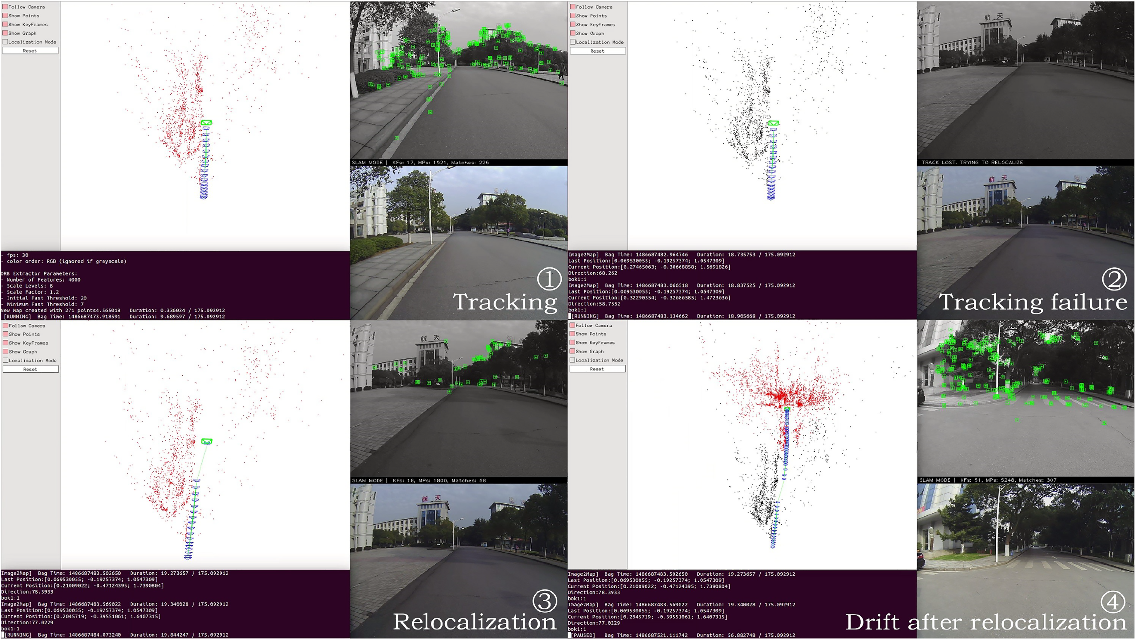
The proposed relocalization system dealing with tracking failure caused by image interruption. While conducting SLAM , we introduced a tracking failure manually by suspending the tracking thread and keeping on moving for 15 s (25 m). After that, we resumed the tracking thread and the tracking failure happened ‚. The proposed system enables the relocalization module automatically and recovered the tracking successfully ③, where a pose was computed and a keyframe was inserted. However, due to the missing data, the scale drift became larger (the space between keyframes became smaller) and the accuracy of pose estimation decreased greatly (there was an obvious deviation between the newly computed camera pose and the previous trajectory) ④. SLAM: simultaneous localization and mapping.

Drift correction results by active loop closure. (a) The corresponding Google map of this outdoor environment. (b) The mapping results of the monocular SLAM after the relocalization, where the black points represent the fixed mappoints, red points represent the mappoints which are currently seen by the robot, blue boxes represent the keyframes and the green line represents the trajectories of the robot. After the relocalization (b), we can see an error of the camera’s pose estimation, zoomed in (c), where there is an obvious deviation between the newly computed camera pose and the previous trajectory. Then, we compared active loop closure (d) (zoomed in (e)) and moving backwards a few meters (f) (zoomed in (g)). We can see that the trajectory of active loop closure shown in (e) is straight and corrected without any deviation, while in the trajectory of just moving backwards a few meters shown in (g), the deviation still exists. SLAM: simultaneous localization and mapping.
To solve the accumulated error and scale drift problem, we proposed an active loop closure method, which has been described in the ‘Active loop closure module’ section. Our system realized the active loop closure using the pose information computed by the relocalization module, and the robot can find a loop actively to correct the drift. We perform the active loop closure module after each relocalization and stop it when finding a loop closure. As a comparison, we also performed the experiment of moving the robot backwards a few meters to revisit missing areas after the relocalization. Comparing the experimental results of these two methods (shown in Figure 4(d) and (f)), we can conclude that active loop closure performs much better in correcting the drift than just moving backwards a few meters.
Dealing with tracking failure caused by image blur
In this experiment, we moved the camera at a high speed and shook it greatly to make the tracking fail during the SLAM process in an indoor office environment to validate that whether the proposed monocular SLAM is robust to the tracking failures caused by the image blur. The experimental results (in Figure 5) show that after combining the relocalization module and active loop closure module, the proposed system works well even in such challenging situation, while the original ORB-SLAM cannot deal with it.

The SLAM results with strong shakes caused by camera’s high-speed motion. While conducting SLAM (a), tracking failure happened due to the strong shake caused by camera’s high-speed motion (b). Our system can rapidly recover the tracking (c), which illustrates that our system has strong robustness even in such challenging situations. (d) The corresponding LiDAR map of the office environment, where the triangle represents the start points, the circle represents the endpoints and the arrows represent the robot’s moving directions. (e) and (f) The mapping results of the monocular SLAM, where the black points represent the fixed mappoints, red points represent the mappoints which are currently seen by the robot, blue boxes represent the keyframes and the green line represents the trajectories of the robot. (e) The result without loop closure. (f) The result with a loop closure. The better performance shown in (f) verifies again that our system can perform better after integrating active loop closure module. SLAM: simultaneous localization and mapping.
Dealing with tracking failure caused by camera sudden motion
In this experiment, we used the image sequence from 00 to 05 from the KITTI data set to test the proposed system. To simulate the tracking failures caused by sudden motion of camera, we randomly chose 50 positions in each sequence, took out image frames close to them and then set the tracking failure manually (by setting the flag tracking lost = true). We tested the relocalization performance on each position by taking out different numbers of frames from 1 to 10. The test results (shown in Figure 6 and Table 1) illustrate that our system can be employed on high-speed cars in large-scale environments (with the total length of 14.6 km) with longest success distance (up to 46 m) and high successful rate of the relocalization (higher than 40%).
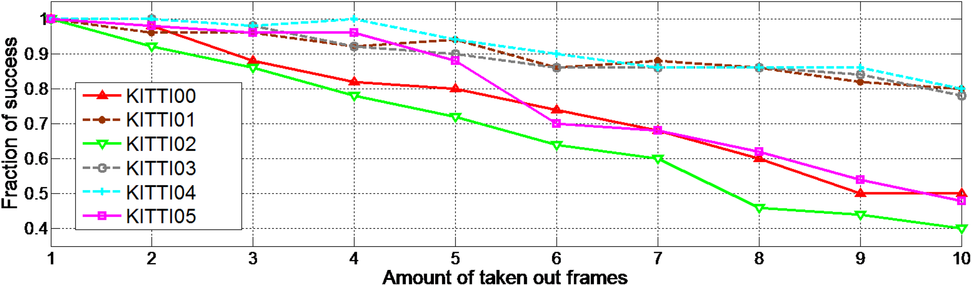
Successful rates of the relocalization on the KITTI data set. The solid lines represent the results in large-scale environments with a lot of bends, while the dashed lines represent the results in the environments without many bends.
Results on the KITTI data set.

a The distance means the length of the trajectory during the tracking failures computed from ground truth.
b In sequence 01, the car runs on a highway environment with small changes, which is not a common situation.
c In sequence 05, since the car runs very slowly, it moves only 9 m during the taken out 104 frames.
Real-time performance
We evaluated the real-time performance of the proposed system and other systems by comparing the computation time needed in each step of the relocalization process. As shown in Table 2, our system (23.2 ms) is faster than those in LSH-based method 3 (183.4 ms) and ORB-SLAM 5 (35.7 ms) and is slightly slower than that in Williams et al.’s work. 1 Furthermore, considering that 2000 features were extracted in our system while only 145 features were extracted in Williams et al.’s work, the real-time performance of our system is quite good. Apart from feature extraction, our system only needs 5.0 ms (the same as Williams et al.’s work) for the relocalization, which is the best among all relocalization methods.
The computation time needed in relocalization process.

LSH: locality sensitive hashing.
b The time consumed by the step of feature extraction includes the time of feature classification.
Precision analysis
Following the original ORB-SLAM, we used the KITTI data set with the relative position error (putting errors in context of space scales) comparing to the given ground truth to evaluate the relocalization accuracy of the proposed system, as shown in Figure 7. We can see that the errors on the KITTI sequences 00 and 05 are obviously smaller than those on the sequences 03 and 04, because there are many loops in the former two sequences. We are surprised to find that with loop closure, our system has the same accuracy (within 6%) as the original ORB-SLAM, even when hundreds of frames were taken out from the image sequence. It verifies again that by combining active loop closure, our system can achieve more robust and accurate relocalization for the monocular visual SLAM.
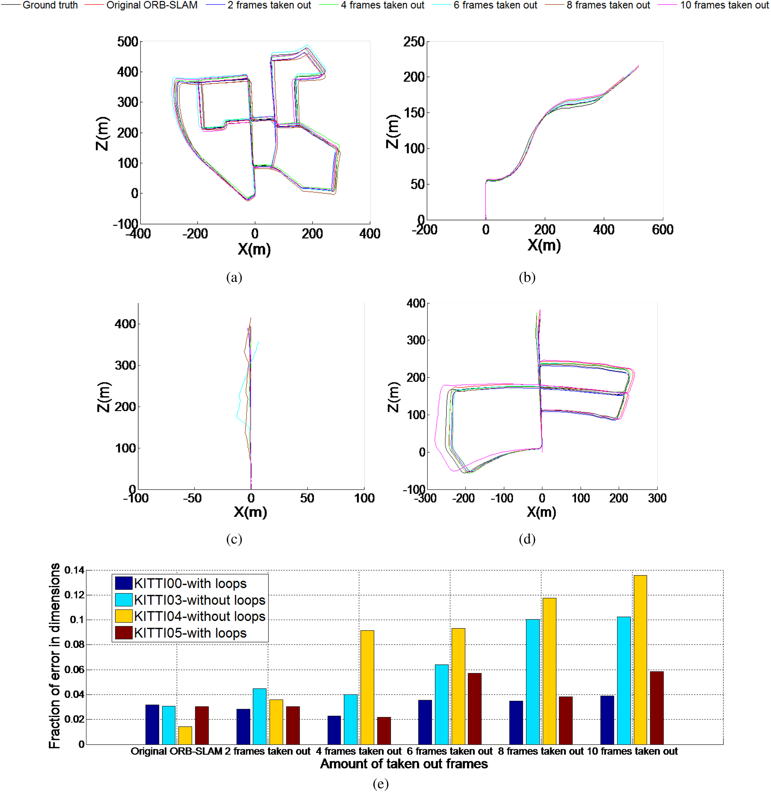
(a) to (d) The experimental results of our system conducted on the KITTI sequences 00, 03, 04 and 05 when different numbers of frames from 1 to 10 were taken out, respectively. (e) The comparison of the fraction of their errors (the estimated position error comparing to the given ground truth) in the context of space scales.
Multi-robot collaborative SLAM.
In this section, two data sets were used: indoor office data set collected by ourselves using handheld cameras and KITTI data set. We used two ELP-USBFHD01 M monocular cameras to perform SLAM simultaneously in each half of the office environment. For the KITTI data set, although it is usually used for single-robot SLAM, concerning the multi-robot mission, we divided the image sequences into several smaller segments and simulated the multi-robot collaborative SLAM by performing SLAM within each segment simultaneously. Map merging cannot be realized with these segments only using overlap-based methods.
Multi-robot communication
Sharing data among robots is a key requirement in multi-robot collaborative SLAM. 58 In this work, we use bridges with ROS to realize a real-time AP-to-AP wireless multi-robot communication. The bridges have many advantages, such as small size and strong penetration, which enable them to achieve long-distance communication and can be used on mobile robots with limited loading capacity. For the format of the shared information, there are two main approaches, sharing raw sensor data 59 and processed data. 32 Sharing raw sensor data is more flexible but requires high bandwidth and reliable communication between robots as well as more processing power. In contrast, sharing maps uses less bandwidth and there is no need to process raw data redundantly. Therefore, we choose to share maps among the group of robots. Considering that the proposed robust monocular SLAM is based on keyframes, we use the basic ROS message elements to design a new map representation, which contains all the information of a keyframe and the relative mappoints. Each robot in the team conducts the same monocular SLAM and, at the same time, shares this kind of message through the wireless network once they create a new keyframe. The communication of multiple robots is shown in Figure 8. From the perspective of robotA , it receives the environment information from FrameA and other robots’ incremental maps, and meanwhile, sharing its own incremental map through keyframeA . As a distributed system, all the robots in the proposed collaborative SLAM system are conducting the same process and sharing the same format of map information. Therefore, every robot can have input topics for all robots in the network, or just communicate with a subset of the robot team. It depends on the number of the robots and the trade-off between the bandwidth and efficiency. We can set the communication topological relations using the ROS topics before each mission according to the demand. We only give an example of realizing the proposed distributed framework using ROS system. However, it does not rely on a specific communication mechanism and, of course, can also be realized on other systems like ROS2.

The wireless communication between multiple robots. From the perspective of robotA, it is receiving the environment information from
Realizing multi-robot SLAM in indoor scenarios
In the first experiment, we used two monocular cameras to simulate two robots performing collaborative SLAM in the office environment. The local maps of each robot were shared through the wireless network using bridges and ROS messages. Figure 9 shows the perspective of robotA . Figure 9(a) is the SLAM result of robotA , while Figure 9(b) is the map received from robotB maintained in the map processing module before map merging. In order to show the difference, we used black and red points to represent the mappoints created by robotA itself and used purple points to represent the mappoints received from other robots.

The perspective of robotA conducting multi-robot SLAM in the indoor environment. (a) The SLAM result of robotA. (b) The map received from robotB maintained in the map processing module. In (a), black points represent the fixed mappoints while red points represent the mappoints which are currently seen by the robot. In (b), the purple points represent the mappoints received from robotB. The blue boxes represent the keyframes, while the green lines represent the edges of the pose graph. SLAM: simultaneous localization and mapping.
Once the same place is detected, the relative pose estimation module will determine the relative poses, and the map merging module will combine these local maps into a global map, as shown in Figure 10. Figure 10(a) illustrates the general map of the indoor office built by a 2D LiDAR, and Figure 10(b) shows the SLAM result after merging the maps of these two robots. In Figure 10(a), the blue line and the red line represent the approximate trajectories of robotA and robotB , respectively. The triangles represent the start points, and the circles represent the endpoints. The overlaps between these two maps are very small, and we can see that the two robots never see each other directly. In other words, there is no direct line-of-sight observations. These experimental results show that our multi-robot SLAM system can be realized in the indoor office environment using two handheld monocular cameras with little overlaps.

The experimental result of the multi-robot collaborative SLAM conducted in the indoor environment. (a) The general map of the indoor office in 2D. (b) The SLAM result after merging the maps of these two robots. In (a), the blue and red lines represent the trajectories of robotA and robotB, respectively. The triangles represent the start points, and the circles represent the endpoints. SLAM: simultaneous localization and mapping.
Realizing multi-robot SLAM in outdoor large-scale scenarios
In this experiment, we used KITTI data set to realize a large-scale multi-robot collaborative SLAM. Although the data set was collected by one vehicle, we split the sequences into several segments and used two computers to simulate two robots performing collaborative SLAM at the same time, or simultaneously conducted SLAM on different sequences and eventually obtained a global map. The images in the KITTI data set were converted into ROS bag files at 10 fps and played in real time.
Experiment on KITTI sequence 00
Taking two robots as an example, Figure 11(a) and (b) shows the SLAM results from the perspective of robotA before map merging. Figure 11(a) shows the local map built by robotA itself and Figure 11(b) shows the local map received from robotB . Figure 11(c) shows the corresponding Google map of this experimental environment. Approximately, robotA travels 750 m (shown in blue) and robotB travels more than 1 km (shown in red). Figure 11(d) shows the final global map acquired by the proposed multi-robot collaborative SLAM. This experiment shows the advantage of the proposed method over other methods that rely on the overlaps of the maps to determine the relative poses. Clearly, in this experiment, the overlap of the maps is very small compared to the size of the maps.
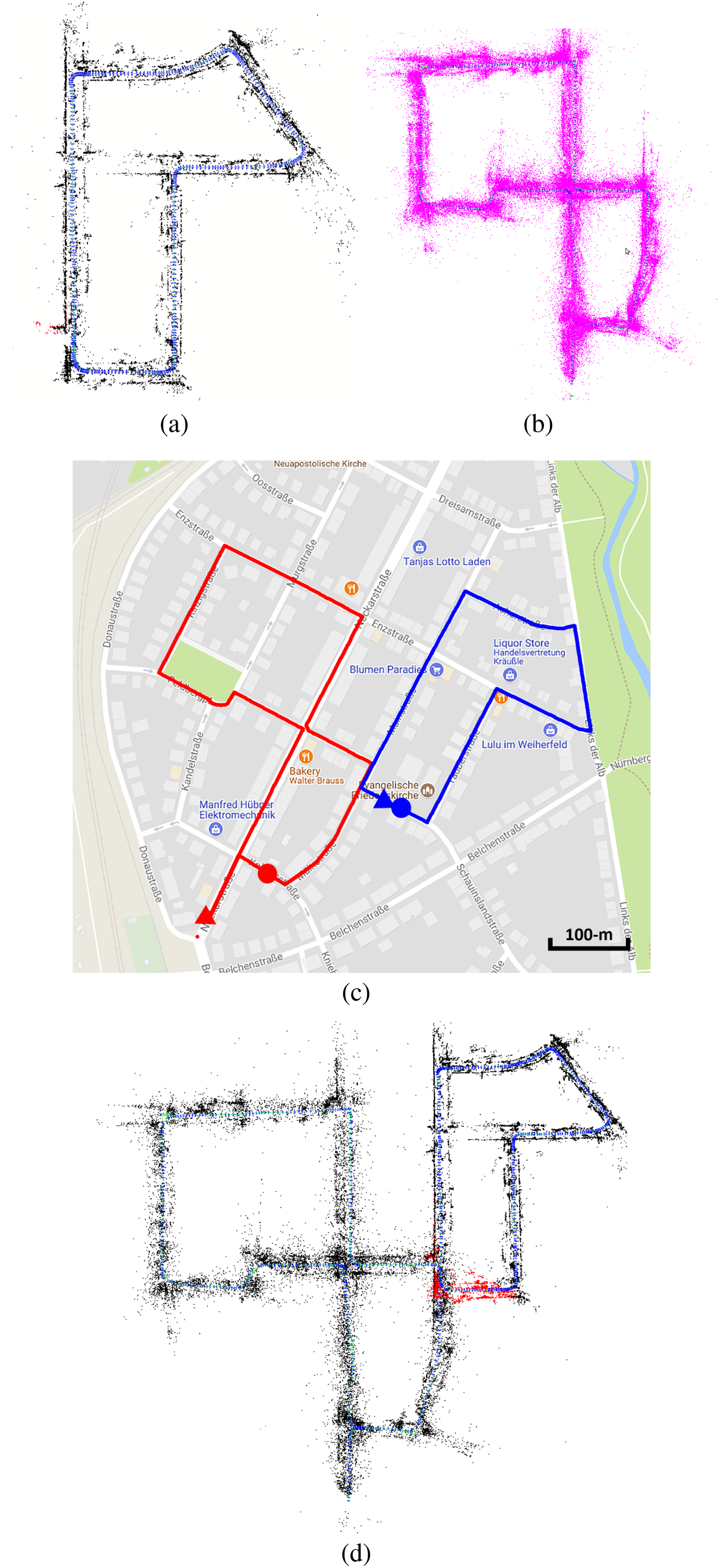
Experimental results on KITTI sequence 00. (a) and (b) The SLAM results from the perspective of robotA before map merging. (a) The local map built by robotA itself and (b) the local map received from robotB. (c) The corresponding Google map of this experiment. The blue and red lines represent the approximate trajectories of robotA and robotB, respectively. (d) The final global map after map merging. SLAM: simultaneous localization and mapping.
Experiment on KITTI sequences 00 and 07
In this experiment, we simultaneously conducted the SLAM on KITTI sequences 00 and 07 to simulate two robots. The image sequences were collected by one vehicle at different time. Therefore, the environment is dynamic which makes it more challenging to realize an outdoor large-scale collaborative SLAM. Figure 12 shows the frames we used to determine the relative poses in these two sequences. It is clear that there is a significant difference between these two images. Figure 13(a) shows the Google map related to these two sequences. The red line represents the approximate trajectory of robotA carrying out the SLAM on sequence 00, while the blue line represents the approximate trajectory of robotB carrying out the SLAM on sequence 07. robotA travels about 3.7 km, while robotB travels 700 m. Figure 13(b) and (c) shows the maps of sequence 07 maintained in the map processing module of robotA and the original map built by robotB , respectively. Figure 13(d) shows the map of sequence 00 built by robotA before map merging, and Figure 13(e) shows the global maps after merging the maps of sequences 00 and 07. This experiment also confirms the ability of the proposed algorithm in performing collaborative SLAM in large-scale environments with little overlaps. It also validates that the proposed system can be used in the real world with moving pedestrians and vehicles.
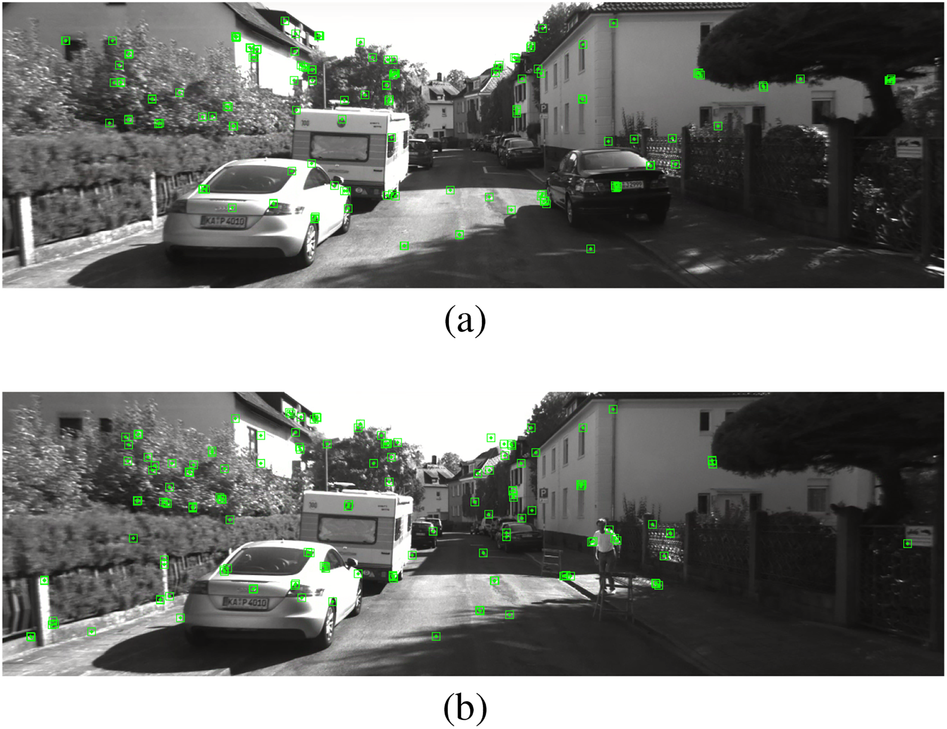
Frames which were successfully used for the appearance-based place recognition. (a) The current keyframe of robotA. (b) The matched keyframe of robotB.

Experimental results on KITTI sequences 00 and 07. (a) The Google map related to these two sequences. (b) and (c) The maps of sequence 07 maintained in map processing module of robotA and the original map built by robotB. (d) The map of sequence 00 built by robotA before map merging. (e) The global map after merging the maps of sequences 00 and sequence 07.
Conclusion
In this article, we proposed a robust monocular SLAM based on image-to-map relocalization and active loop closure to solve the well-known tracking failure problem in the monocular SLAM. Based on the robust monocular SLAM, we realized a distributed multi-robot collaborative SLAM system in both indoor small-scale and outdoor large-scale environments. The experimental results show that better robustness can be achieved by our system than other relocalization systems, and the proposed robust monocular SLAM system can be employed in most challenging situations even in previously unvisited places. By combining the active loop closure with the relocalization, high accuracy and efficiency can be achieved simultaneously, which also provides a good example to answer the ‘when to use’ problem in the active SLAM. Based on the robust monocular SLAM, the proposed multi-robot collaborative SLAM system can well address the relative pose estimation and map merging problem with least requirements on the motion of the robots and the overlaps of the local maps obtained by each robot. The experimental results show that our multi-robot collaborative SLAM system can be realized in real time in both indoor and outdoor large-scale environments.
In this work, we just give a simple example of using the pose information estimated by the proposed relocalization method to realize an active loop closure. In the future, it would be desirable to run our system on real robots with advanced path planning and robot controlling algorithms. Also, we will use more real robots to test our system and find a better way to represent the map to further reduce the amount of calculation and storage.
Footnotes
Declaration of conflicting interests
The author(s) declared no potential conflicts of interest with respect to the research, authorship, and/or publication of this article.
Funding
The author(s) disclosed receipt of the following financial support for the research, authorship, and/or publication of this article: This work was supported by National Science Foundation of China (nos 61503401 and 61773393).