The intensification of regulations on greenhouse gas emissions and pollutants has underscored the necessity for advanced injector concepts that ensure fuel flexibility and scalability, addressing critical demands within the thermochemical energy conversion sector. An additively manufactured µ-slit injector is proposed and evaluated across a wide range of operating conditions, including variations in jet velocity, fuel loading, air preheating temperature, and fuel type. Detached fuel film dynamics are analysed using machine learning-based object detection, revealing reduced film length with increasing jet velocity and decreasing mass flow rate, ensuring uniform radial distribution. Phase Doppler interferometry confirms the production of fine droplets, with an average diameter of 20 µm, inherently generated by the µ-scale fuel outlet design while maintaining a low pressure drop. Combustion performance, assessed via OH-chemiluminescence for H, CH, ethanol, and Jet A1, shows excellent stability for H across both low- and high-momentum jet regimes, attributed to enhanced turbulent mixing driven by the high density ratio. In contrast, CH and Jet A1 exhibit similar lift-off trends. Ethanol and Jet A1 display significant pressure drop increases at high preheating condition, highlighting pre-vapourisation effects. Additionally, a correlation for gaseous fuels between the pressure drop and fluid property ratios is established, consistent with turbulent flow theory, and further extended by incorporating the injector discharge coefficient and compressibility effects. These results demonstrate that the µ-slit injector seamlessly accommodates both gaseous and liquid fuels, delivering exceptional fuel flexibility and scalability, and positioning it as a promising candidate for industrial burners, micro-gas turbines, and hybrid aero-engine systems.
In recent years, the shift from centralised power generation to decentralised energy systems has gained significant momentum, particularly for industrial-scale gas turbines below 20 MW that are increasingly deployed in data-centre applications.1 Micro-gas turbines (MGTs) have emerged as a key technology, driving the advancement of smart energy grids offering scalable and flexible solutions for the transportation and industrial sectors.2,3 Furthermore, based on intensification of emission regulation for decarbonisation roadmaps with renewable energy sources, the development of future MGT systems are more focusing on utilising carbon-neutral fuels. These include hydrogen (H), ammonia (NH), biofuels, and sustainable aviation fuels (SAFs), which are being adopted across various MGT application sectors.4,5 For this purpose, the expanding MGT market requires advanced combustion systems that can deliver scalability and fuel flexibility while achieving substantial emission reductions.
High momentum jet-stabilised combustion (HMJC) systems have been introduced to tackle the fuel-flexible gas turbine market, offering the ability to operate with fuels ranging from pure H to extra-light heating oil while maintaining low emissions, as demonstrated in various studies.6,7 For gaseous fuelled systems, Raveesh et al.8 investigated the reaction zone structure for jet velocities of 30 and 60 m/s, corresponding to Reynolds numbers from 3040 to 10,027, and for varying CO content in biogas. The reaction zone was described via O-atom radical and CO planar laser induced fluorescence (PLIF), in combination with numerical simulations, under moderate or intense low-oxygen dilution (MILD) conditions. The study characterised the transition of jet flames into MILD combustion with increasing CO dilution, accompanied by reduced emissions and diminished chemiluminescence. Yang et al.9 investigated fuels with hydrogen contents ranging from 0% to 100% at a jet velocity of 100 m/s, using different fuel injection concepts integrated into dual coaxial jet configurations, and reported excellent NOx and CO emission performance. Lingstädt et al.10 examined low calorific solid oxide fuel cell-off gases at velocities ranging approximately from 25 to 70 m/s, using multiple nozzle concepts in a demonstrator plant, and observed the general flow field and flame shape through combined numerical simulations and experiments. Furthermore, the scalability of these systems for industrial applications and their fuel flexibility with gaseous fuels are also successfully validated.11,12 While these systems excel with gaseous fuels, translating the advantages of jet-stabilised combustion to liquid fuel operation is often constrained by the need for substantial structural modifications to the injection concept. Moreover, fuel injection concepts capable of accommodating both gaseous and liquid phases are rarely reported.
For liquid-fuelled HMJC systems, the scalability and high fuel flexibility of jet-stabilised combustors designed for compact engines have been evaluated using dual-pressure swirl (PS) and airblast (AB) injectors.7 These advantages have already secured HMJC systems a place in the industrial sector’s portfolio of stationary gas turbines capable of operating with both gaseous and liquid fuels.613–15 Furthermore, jet-stabilisation concepts have been tested at various burner scales and in industrial applications under combustion modes such as MILD and flameless oxidation (FLOX).16 In a furnace combustor, Ye et al.17 evaluated the NOx and CO emission characteristics for ethanol, acetone, and n-heptane at a thermal power of 4.7 kW, with Reynolds numbers ranging from 5000 to 14,000 (corresponding to jet velocities of 12–35 m/s). Luhmann et al.18 investigated the FLOX concept in an oil burner over a thermal power range of 50–150 kW, reporting good combustion performance with low NOx and CO emissions. At higher thermal powers, Arghode et al.19 introduced an ultra-high thermal intensity in the range of 156–198 MW/m atm for both gaseous- and liquid-fuel operation, with air jet velocities of 90 m/s, achieving NOx emissions below 10 ppm. The growing utilisation of jet stabilising systems for broad industrial applications with high fuel flexibility necessitates the development of scalable injector concepts characterised by robust operational performance. To this end, geometric modifications such as altering wall-film length and integrating low-swirlers have been explored.20–23 However, conventional PS injectors with an orifice injection hole for fuel distribution inherently incur high kinematic losses, limit design freedom, and consequently restrict scalability and fuel flexibility. This calls for the meticulous optimisation of injector designs to achieve a balance of simplicity and resilience in flow control, irrespective of fuel phase or properties, thereby maximising the potential of jet-stabilised combustion mechanisms.
To address this limitation, additive manufacturing of metals is increasingly being applied to gas turbine burners, leveraging its flexibility in creating complex, flow optimised structures with reduced assembly tolerances. Giuliani et al.24 demonstrated that additively manufactured (AM) swirler designs can outperform traditional designs, particularly near the lean flammability limit. In the domain of meso- and micro-scale burner concepts with CH premixed flames, Rajasegar et al.25 developed AM meso-scale combustors stabilised with swirling jets, outperforming macro-scale designs in power density, performance, and emission characteristics. Furthermore, for hydrogen flames, Kim et al.26 presented an overview of the development of AM micro-mix burners for aircraft engines, highlighting successful optimisation achieved through numerical and empirical methods. Recently, Durocher et al.27 introduced an AM micro-mix nozzle capable of operating with fuels from pure CH to H, demonstrating stable combustion across various mixing concepts with high fuel flexibility, broad stability limits, and low susceptibility to combustion instabilities. Despite the advancements achieved with gaseous fuels, the application of additive manufacturing to liquid fuel combustor nozzles faces significant challenges in achieving effective atomisation which is directly coupled with combustion performances. These challenges include achieving nozzle dimensions below 200 µm for MGT applications, maintaining manufacturing tolerances within single-digit micrometers, and understanding the effects of surface roughness to mitigate flow disturbances and coking tendencies. Guddati et al.28 emphasised the difficulty of creating structures with feature sizes smaller than 100 µm using additive manufacturing, identifying it as a significant limitation. Crayford et al.29 investigated AM airblast liquid atomisers through droplet sizing and demonstrated that, although additively manufactured designs can match conventional performance, their elevated surface roughness restricts air-flow passages and increases pressure drop.20,21 Additionally, Adamou et al.30 evaluated an AM vapourisation injector featuring 200 µm holes through numerical and experimental approaches, demonstrating more complex combustion behaviour. Nonetheless, overcoming these manufacturing challenges and rigorously assessing extreme design solutions are essential steps toward achieving a universal injector capable of seamlessly accommodating both gaseous and liquid fuels without requiring structural or design modifications. Advancing this capability is crucial to fully unlocking the potential of AM for enabling fuel-flexible as well as geometrically and operationally scalable combustion systems. When combined with the annular-slit concept, this approach allows the injector to be proportionally adapted to various combustor scale and operating powers while maintaining excellent atomisation and mixing performance. Furthermore, it is noteworthy that when fabricated as an integrated part of the burner assembly, including multitude nozzle configurations, the AM injector incurs virtually no additional manufacturing cost. The additive manufacturing approach eliminates conventional assembly, welding, and tolerance adjustment steps, thereby reducing overall cost and simplifying production. In addition, it enables mass customisation, on-demand and decentralised manufacturing, and real design optimisation, providing greater flexibility for future combustor development.31–33
In this context, a newly developed AM µ-slit injector concept is proposed, designed to accommodate both gaseous and liquid fuels without requiring structural modifications. The injector design delivers high-quality atomisation, homogeneous mixing, and broad load controllability while maintaining full fuel flexibility. Its performance is assessed across variations in fuel type, jet velocity, preheated air temperature, and thermal power, thereby demonstrating seamless transition between liquid and gaseous fuels with wide operating ranges. The spray characteristics are analysed using shadowgraphy to visualise global spray formation, supported by statistical analysis with machine learning (ML)-based object detection near the nozzle exit. Phase Doppler interferometry provides quantified data of droplet size distributions and velocity components at various radial and axial locations. The combustion behaviour is assessed using hydroxyl chemiluminescence (OH-CL) imaging for four different fuel types across various preheating temperatures. The injector’s dynamic load performance is evaluated by measuring pressure drop and examining its engineering correlations. The structure of this article is as follows: the ‘Experimental and diagnostic setup’ section presents the jet spray burner and injector configuration, the operating conditions, and the diagnostic techniques used. The ‘Statistical analysis methods’ section details the applied post-processing methods. The ‘Results and discussion’ section discusses the experimental findings, and the ‘Conclusions’ section provides the concluding remarks.
Experimental and diagnostic setup
The AM µ-slit injector, alongside the custom designed single nozzle piloted jet spray burner (PJSB)21 and the diagnostic setup, are detailed in this section.
Burner facility
The single nozzle PJSB is presented in Figure 1. The burner is comprised of four essential components: an air pre-conditioning and contraction nozzle, a main combustor nozzle, a liquid fuel injection system incorporating the AM µ-slit injector assembly, and a pilot flame burner surrounded by a shielding air flow channel. To mitigate disturbances at the inlet, the main airflow is redirected through multiple deflections and a porous plate before reaching the contraction nozzle, designed to minimise flow separation following wind tunnel guidelines, reducing the air plenum diameter from 60 to 12 mm. The combustion nozzle has an internal diameter () of 12 mm and an external diameter of 16 mm, with an adjustable cylindrical section length (8 [–] 15) using spacers and injector holders. The annular µ-slit injector is positioned concentrically within the combustor nozzle and supported by inner and outer straight vanes on the airblast wall, as depicted in the inset cross-sectional view. The co-annular pilot burner, with internal and external diameters of 16 and 78 mm, respectively, provides a stable ignition source to the main spray flame. The pilot operates using a homogenised mixture of 80 H / 20 CH/air, mixed and distributed through an AM flow unit that also acts as a flashback arrestor.31 Circumferentially tilted perforations in the pilot top plenum ensure uniform distribution, while an AM porous plate stabilises the premixed flames. A shield air stream, positioned 15 mm above the pilot sintered plate, isolates the pilot flame. All gas flows for the burner system, including the pilot flame, are regulated by calibrated mass flow controllers (Bronkhorst, inflow series). The main combustion air can be preheated up to 800 K using a PID-regulated inline heater (Leister LE 10000 DF-R).
Half-cut view illustration of the burner assembly featuring the developed additively manufactured (AM) µ-slit injector. Flow paths of the main air, fuel, pilot mixture, and shield air are indicated by arrows. Key components are labelled using coloured lines and boxes and the coordinate system on top of the combustor nozzle. The inset shows the A-A cross-sectional view, illustrating the concentric annular slit of the fuel injector surrounding the combustor nozzle.
AM µ-slit injector
Figure 2(a) schematically illustrates the µ-slit injector within the combustor nozzle, with colours assigned to each flow section. Fuel enters the plenum and flows through a cylindrical passage (blue section) to the top. The fuel then passes through a contraction at the interface between the airblast wall and the inner air-guiding wall film, before being discharged through a semi-deterministic slit with a width of 50 µm and a height of 2 mm, as shown in Figure 2(b). The airblast wall acts as a liquid film spreader with carrier air (yellow section). Lastly, atomisation air (green section) flow surrounding airblast wall generates high shear forces with the carrier air. The slit terminates 16 mm () upstream of the airblast wall edge. The outer vanes are located at 18 mm () upstream from the airblast edge and have a vane length of 11 mm (). The inner vanes, with a 5 mm diameter () and a length of 6 mm (), are introduced to facilitate air flow modulation for effective atomisation.21 In the present study, inner and outer vanes are straight. The AM injector, fabricated using Inconel 718, has a minimum achievable printing wall thickness of 80 µm, close to three times the laser spot size (). Lastly, AM µ-slit injector produces fine droplets and homogeneous fuel placement with a stable flame, as shown in Figure 2(d). The latter shows a direct jet spray flame with a raw one phase structured laser illumination planar imaging (SLIPI) image.
Illustration of the assembled single nozzle combustor with the developed µ-slit injector (a). The colour-shaded sections represent the flow passages. Panel (b) shows a direct microscope image from the top. On the right-hand side, the schematic of AM µ-slit injector (c) is presented, including corresponding parts labelled and the coordinate system on top of the airblast wall. Panel (d) shows a direct image under the baseline operating condition alongside a corresponding 1p SLIPI image, visualising the droplet-laden area.
Diagnostic setup
A three-phase Doppler interferometry system (PDI-300 MD, Artium Technologies Inc.) is utilised to measure the droplet size distribution and velocity components. The transmission optics have a focal length of 350 mm and a beam separation of 60 mm, yielding nominal beam waist diameters of 169, 156, and 179 µm for the three laser pairs. For the three velocity component measurements, the transmitter units, are equipped with three inbuilt diode-pumped solid-state lasers. The PDI receiver is capturing the signals in a 40 forward light-scattering configuration, with receiver optics featuring a fixed 350 mm focal length and an aperture slit width of 100 µm. These specifications allow for droplet size measurements ranging from 0.7 to 112 µm.
Background illuminated shadowgraphy is used to visualise and quantify the liquid penetration depth and its area. Illumination is provided by the second harmonic of a Nd:YAG laser (10 Hz), which is directed onto a white diffuser and a fluorescent plate. The fluorescent plate exhibits peak emission at 655 nm with a decay time of 20 ns. Image acquisition is performed using a backside illuminated CMOS camera (LaVision CX12) equipped with a 180 mm Sigma macro lens at /2.8. The resulting field of view is mm, with a resolution of pixel, corresponding to a measured optical resolution of 7 µm, validated with a USAF 1951 target (Thorlabs, R3L3S1N).
To characterise the combustion process, OH chemiluminescence imaging is conducted to evaluate flame lift-off height and penetration length. An intensified relay optic system (LaVision, NanoStar), combined with a Halle UV quartz lens and a narrow band-pass filter (AHF, peak transmission of 85, 310 15 nm), captures up to 200 instantaneous images at a rate of 10 Hz. The field of view is mm with an image resolution of 2048 2048 pixels, yielding a calibrated spatial resolution of 320 µm per pixel, determined using a USAF 1951 resolution target. Background corrections are made using reference images to adjust local background signals based on intensity ratios. A uniform filter is applied, and noise is mitigated by filtering out intensity outliers based on probability density functions.
Operating conditions
A wide range of thermal power cases, encompassing both gaseous and liquid fuel bases, are investigated using the PJSB system featuring the µ-slit injector concepts. In this context, reference cases are selected for two conditions: low ( m/s) and high ( m/s) air jet velocities. Low jet momentum conditions are representative for operation of industrial burners such as process heaters and boilers, whereas high jet momentum cases simulate conditions encountered in gas turbine applications. The overall variations in operating condition are detailed in Table 1.
Summary of the operating conditions for various fuel types tested with the µ-slit injector, focusing on pressure drop, atomisation, and combustion performance. The and denote the preheated temperature and velocity, respectively. The mass flow rate is represented by , with subscripts and referring to the air jet and fuel cases. The symbol indicates the equivalence ratio, while denotes the thermal power under each test scenario. is the jet Reynolds number.
[K]
[m/s]
[g/s]
[g/s]
[–]
[kW]
[–]
H
300
30
3.18–3.76
0.02–0.03
0.2–0.6
1.97–6.71
1.90–2.24
300
120
14.7
0.09
0.20
10.3
8.76
400
120
11.1
0.07
0.20
7.75
5.26
500
120
8.84
0.05
0.20
6.20
3.50
650
100–140
5.67–7.93
0.03–0.05
0.15–0.25
3.65–5.85
1.82–2.55
CH
300
30
3.42–3.75
0.13–0.28
0.60–1.40
6.57–14.2
2.20–2.24
300
120
14.7
0.68
0.80
34.4
8.76
400
120
11.1
0.51
0.80
25.8
5.26
500
120
8.84
0.41
0.80
20.6
3.50
650
100–140
5.67–7.93
0.24–0.52
0.60–1.40
12.1–26.3
1.82–2.55
Jet A1
300
20–90
2.66–11.9
0.16–0.38
0.27–1.39
6.88–16.4
1.59–7.09
350
120
13.7
0.10–0.50
0.10–0.42
4.30–21.5
7.22
500
80–160
6.38–12.8
0.10–0.80
0.23–1.85
4.30–34.4
2.53–5.07
650
120
7.37
0.10–0.80
0.60–1.40
4.30–34.4
2.37
Ethanol
300
120
15.9
0.10–0.40
0.06–0.23
2.67–10.7
9.48
350
120
13.7
0.10–0.40
0.07–0.26
2.67–10.7
7.22
500
120
9.58
0.10–0.40
0.10–0.38
2.67–10.7
3.79
For gaseous fuel cases under low jet momentum operation, the baseline condition is = 30 m/s and = 300 K. The global equivalence ratio () varies from ultra-lean conditions at for H to rich conditions up to 1.4 for CH, resulting in thermal powers () from 1.97–6.71 kW for H and up to 14.2 kW for CH. Here, reflects the combined mass flow of air and gaseous fuel, while is defined as the ratio of the actual fuel to oxidiser mass ratio to the corresponding stoichiometric ratio. For the liquid fuel case, = 30 m/s, = 0.22 g/s for Jet A1, and a fixed = 300 K is taken as reference conditions. The values of and are varied from 20 to 90 m/s and 0.16 to 0.38 g/s, respectively, corresponding to thermal power () ranges from 1.53 to 6.89 kW.
For high jet momentum regime, ultra-lean equivalence ratios in the range of 0.15–0.25 are tested for H, corresponding to a thermal power () range of 3.65–10.3 kW. The operating range for H is constrained by the inlet pressure limitation of the experimental facility. For CH, is varied from 0.8 to 1.4, covering a range of 12.1–34.4 kW. The baseline jet velocity is set at 120 m/s and varied from 100 to 140 m/s. The Mach number () at the µ-slit exit for the gaseous fuel streams is defined as . The speed of sound is given by , where denotes the specific heat ratio, is the specific gas constant, and is the mean of the inlet fuel temperature and the air preheat jet temperature. The exit velocity, , is estimated from the mass flow rate as , where is the fuel density corrected for at 1 atm, and is the cross-sectional exit area determined by the slit width of 50 µm. The Mach numbers indicate that the H jets span from 0.16 to 0.79, whereas the CH cases extend from 0.45 to 1.63. When evaluated using the local density in channel, the local () are notably reduced, ranging from 0.09 to 0.15 for H and 0.15 to 0.21 for CH under the present operating conditions. Here, represents the local density in the microchannel, corrected for temperature and pressure variations according to the wall-film conditions along the channel. Thus, compressibility is likely to affect the flow in the final µ-slit passage. It should also be noted that the µ-channel geometry and its associated surface roughness may further reduce the Mach number, owing to the viscous and frictional losses.34 The Damköhler number () is evaluated to quantify the balance between flow residence and chemical time-scales, defined as , with and . Here, is the estimated minimal integral length scale in shear flow,35 while the laminar flame thickness () and speed () are obtained using freely propagating flame calculations36 in combination with the C-subset of the DLR concise reaction mechanism37 in Cantera. In the current sprays, the droplet velocity fluctuations () present a conservative estimate of the gas phase velocity fluctuations, yet the Stokes number remain predominately well below unity. The results are compared in SMM Figure S3 across the operating conditions.
In the liquid fuel tests, Jet A1 and ethanol are examined at baseline conditions of = 120 m/s, = 0.4 g/s, and = 500 K. For Jet A1, is varied from 80 to 160 m/s, while for ethanol it is fixed at 120 m/s. The is varied in the range 0.10–0.80 g/s for Jet A1 and 0.10–0.40 g/s for ethanol, corresponding to a thermal power range of 2.67–34.4 kW for both fuels. An exceptionally wide range of 0.06–1.85 is explored. The air preheat temperature () is varied between 300 K and 650 K for gaseous fuels and Jet A1, whereas for ethanol it is constrained to 500 K due to significant pressure fluctuations caused by pre-vapourisation within the slit µ-channels. Variations in lead to notable changes in reactivity, density, surface tension, and viscosity due to thermal energy transfer from the preheated air to the fuel, increasing its temperature . The latter is not presented here, as an accurate measure inside the µ-scale channels is extremely challenging due to limited access.
The jet Reynolds number (), given by , exhibits a wide operating range in the single injector configuration, spanning from 1.90 to 8.76 10 for gaseous fuel and from 1.59 to 9.48 10 for liquid fuel, respectively. For Jet A1 in the high velocity regime, the droplet Reynolds number () ranges from 3.55 to 10.4, while the Weber number (), calculated using the slip velocity between the droplet and gas phases, ranges from 0.04 to 0.16. The Weber number is determined as , where denotes the mean slip velocity and the mean droplet diameter. The gas velocity is conditioned for droplets with diameters µm, for which the Stokes number remains well below unity38 to assure sufficient responsiveness of droplets to the turbulent fluctuations of the gas phase. The Ohnesorge number (), defined as , ranges from 5.5 to 9.9 , where is the dynamic viscosity of Jet A1 at the liquid fuel inlet temperature. The heat transfer from the preheated jet to the liquid fuel is not accounted for in this analysis, as it cannot be directly measured, although it would further decrease the surface tension. For the pilot flame conditions, a premixed 80 H2/20 CH4 with air at a constant unburnt bulk velocity of 1.5 m/s, an of 0.65, and an adiabatic flame temperature () of 1850 K, delivers a thermal output of 14.6 kW. Overall, the tested ranges of jet velocity and encompass both low and high velocity operations as well as wide thermal power variations, making the results relevant to various scales of industrial application.9,10,12,17–19
Statistical analysis methods
ML-based object detection model for statistical analysis of liquid film
The statistical analysis involves first detecting the spray surface using a previously developed ML model39 and then extracting a contour of the gas–liquid interface (GLI), the GLI characteristics is used to quantify the primary atomisation process and delineate the involved effects. For this study, semanticFPN is applied as a generalised segmentation framework for shadowgraphy data.40 This model is trained on a single spray configuration but demonstrates the capability to segment entirely new, unseen spray patterns effectively, underscoring its adaptability. The atomisation process analysis is carried out as follows. First, a precise, closed contour is detected to delineate the GLI of the detached liquid film as it extends from the µ-slit and interacts with the high-shear airflow. For the present study, only the liquid film detached from the airblast wall and not separated ligaments are considered, that is, the largest detected contours, as described by Jose et al.39 The entire contour is then divided into 0.25 mm wide segments, producing 40 bins along the airblast edge direction (). For each frame, the maximum penetration depth of the liquid film () in the -direction is identified as shown in Figure 3. Additionally, the detached liquid film area () projected onto the – plane for the whole frame is calculated.
Illustration of the quantities extracted from each image using developed machine learning (ML)-based object detection model,39 Here, denotes the maximum penetration length of each bin of the detached liquid film. The red dot indicates the point of the maximum detachment, while the blue line marks the edge of airblast wall, where = 0. The vertical arrow indicates the direction of the carrier air and liquid fuel injection, and the coordinate system is shown by the red lines.
Phase Doppler interferometry analysis
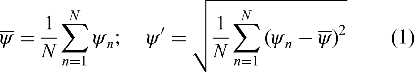
Measurements at each location are conducted for up to 10 10 data points or a maximum duration of 10 seconds to capture the droplet velocity components and sizes (). The optical setup is calibrated for each operating condition. To correct bias from the Gaussian laser intensity distribution favouring larger droplets, the probe volume correction (PVC) method is applied.41 The processed data include raw measurements, mean values (), standard deviations (), where represents the respective data set value as shown in the following equation:
Statistical OH-CL analysis
The combustion process is characterised using both instantaneous and mean OH-CL images. The flame lift-off height (), maximum intensity location (), and penetration length () are determined by analysing radial intensity profiles along the axial direction as detailed by Hampp et al.7 The and values are identified within the first and last 10 of the position arrays for each instantaneous filtered image, with outliers systematically excluded. For , the maximum intensity locations are identified using the interquartile range of the data set, after which and are evaluated. This approach effectively captures local ignition kernels and extinction behaviours.
Results and discussion
Spray and droplet characterisation
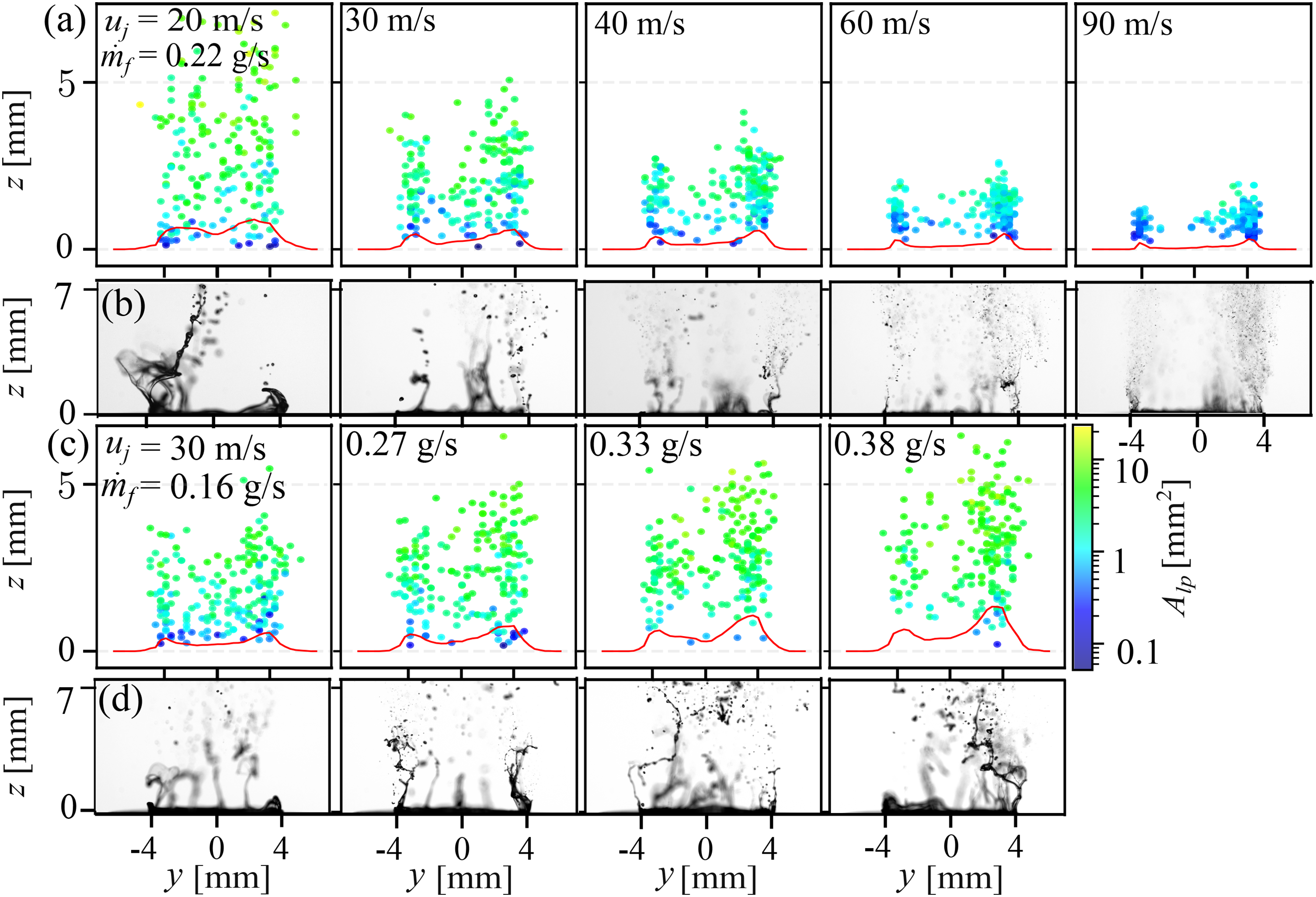
Sample background illuminated shadowgraphy images and their ML-based statistical analysis are presented in Figure 4 for various values of ((a) and (b)) and ((c) and (d)) of Jet A1. The first and third rows present the instantaneous liquid penetration length () as scatter plots, with the sectionalised projected film area () colour coded. Rows (b) and (d) present instantaneous shadowgraphy images for the corresponding operating conditions shown in the upper row plots. At low jet momentum ( 20 m/s), as shown in row (a), the weak shear force between the liquid and gas streams significantly extends to 5 mm, with enlarged film areas of 5 mm. Increasing to 30 m/s confines to 5 mm, while decreases to below 5 mm near the nozzle exit at 2 mm. Further increases in at 90 m/s reduce to 2 mm and shrink to < 2 mm. This enhanced atomisation process, driven by aerodynamic forces, is clearly visible in the shadowgraphy images in row (b), showing the transition from a bulk detached film to direct secondary atomisation, bypassing the ligament breakup stage. This high air-to-liquid momentum ratio stimulates early film break-up, aligning well with the behaviour of conventional pressure-swirl prefilming airblast injectors.7,42 Mean trends, marked by red solid lines, show reasonable axial symmetry. Meanwhile, fuel loading effects, as shown in rows (c) and (d), indicate that increasing up to 0.38 g/s elongates to 5 mm, with reaching 10 mm. However, higher increases asymmetric fuel placement to some degree. This can be improved by the integration of AM features on the surface, longer wall film length, and imposing low-circumferential velocity at co-axial airflow.21,43 It is noteworthy that even under unfavourable atomisation conditions, such as a low air-to-liquid mass ratio (10.5–24.9), the primary breakup length remains below 7 mm, accompanied by a uniform fuel distribution along the radial direction.
Scatter plot for the maximum instantaneous penetration depth () of the liquid film segment plotted against different air coflow velocities () ranging from 20 to 90 m/s, with a constant Jet A1 mass flow rate ( 0.22 g/s) in the first row. The third row presents the same analysis for varying fuel mass flow rates between 0.16 and 0.38 g/s, while maintaining a fixed coflow air velocity of 30 m/s. The scatters are colour-coded to represent the area of the liquid film in each instantaneous snapshot. The red lines present the mean calculated across all images. Instantaneous shadowgraphy images corresponding to each condition are displayed in the panels below.
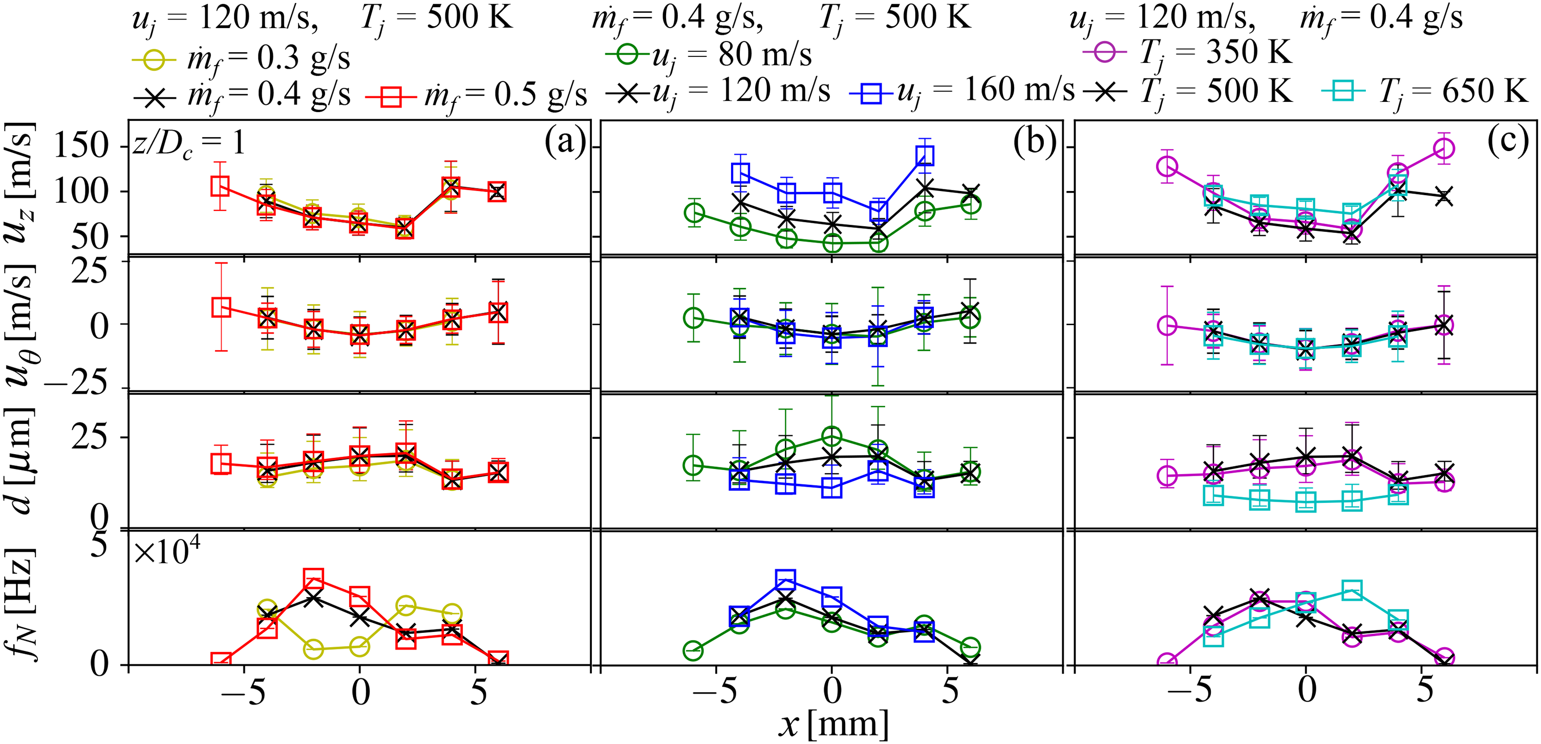
To quantify this further, Figure 5 shows the axial () and circumferential () velocity components, droplet size (), and signal rate () for various operating ranges: Jet A1 fuel loading (a), jet velocity (b), and air preheating temperature (c). For (a), and are set to 120 m/s and 500 K as reference conditions. Under baseline conditions with 0.4 g/s, the profile exhibits a concave shape, with a minimum average of 65 m/s at 2 mm and a maximum of 97.5 m/s at 4 mm along the radial direction. The remains close to zero at the nozzle centre but exhibits a small positive bias across the radial direction, with mean values up to 5 m/s at the nozzle edge. This is likely caused by a slight tilt of the injector or a minor misalignment of the measurement plane, introducing a weak lateral velocity component. Meanwhile, shows a maximum value of 23 µm within 2 mm, with a weak convex profile. The average and its deviation across the radial direction are 18.5 µm and 8.5, respectively, indicating excellent fuel placement and a stable size distribution. Increasing liquid fuel loading induces minimal changes in velocity components and droplet size, as reported by Kang et al.,21 but the droplet signal rate () expands radially by 50 and exhibits an increase in maximum from 2.3 10 Hz to 3.3 10 Hz as increases from 0.3 to 0.5 g/s.
Droplet velocity components (, ) are displayed in the first and second rows, respectively, while droplet size () and signal rate () are shown in the third and fourth rows along the radial () direction at an axial position of ( 1). The symbols indicate mean values, while the bars represent the standard deviation for velocity components and the upper and lower ends for the droplet size distribution. The first column (a) shows the effect of liquid loading. Column (b) demonstrates the impact of aerodynamic forces with varying . Finally, column (c) depicts the influences of with variance from 350 to 650 K.
Conversely, increasing the atomisation air jet velocity from 80 to 160 m/s, while maintaining 500 K and 0.4 g/s, as shown in column (b), significantly elevates from 48 to 100 m/s at the nozzle centre. While increases with jet velocity across the entire radial profile, remains at a plateau near zero. Regarding droplet size distributions, increasing from 80 to 160 m/s reduces from 25 to 12 µm at 0 mm, with the upper limit of decreasing from 36.9 to 17.6 µm. However, vertically above the airblast edge ( 4 mm) remains consistent at an average of 14.5 µm regardless of . This indicates that high-shear force at airblast wall edge promotes atomisation, leading to small droplet size even at the lowest .7 Increasing confines the radial distribution of to 4 mm, with an elevated of up to 3.2 10 Hz. Thus, an increase in confines fuel placement stronger into the jet core, enhancing initial mixture stratification. This indicates aerodynamic forces for atomisation and radial fuel placement can be optimised. To investigate the effects of air preheating, which alters liquid properties such as surface tension and viscosity through heat transfer, column (c) of Figure 5 is examined. Increasing from 350 K to 500 K results in a marginal rise in , while at 650 K, increases moderately from 58 to 80 m/s at 2 mm. The effect of on is negligible. At 500 K, remains constant with 350 K at an average of 14.7 µm across the radial direction. However, at 650 K, the mean droplet diameter decreases markedly to 7.9 µm, which can be attributed to the pre-vapourisation of liquid Jet A1 caused by heat transfer from the injector wall to the liquid fuel. Moreover, within the present range of , where atomisation is governed by surface tension, the reduction in with increasing consequently enhances atomisation and facilitates the formation of finer droplets. The radial distribution of narrows by 50 as increases to 650 K, while the average remains constant at 2.6 10 Hz within 2 mm. The excellent atomisation and homogeneous fuel placement can be directly transferred to advantageous combustion performance as analysed next.
Combustion characterisation
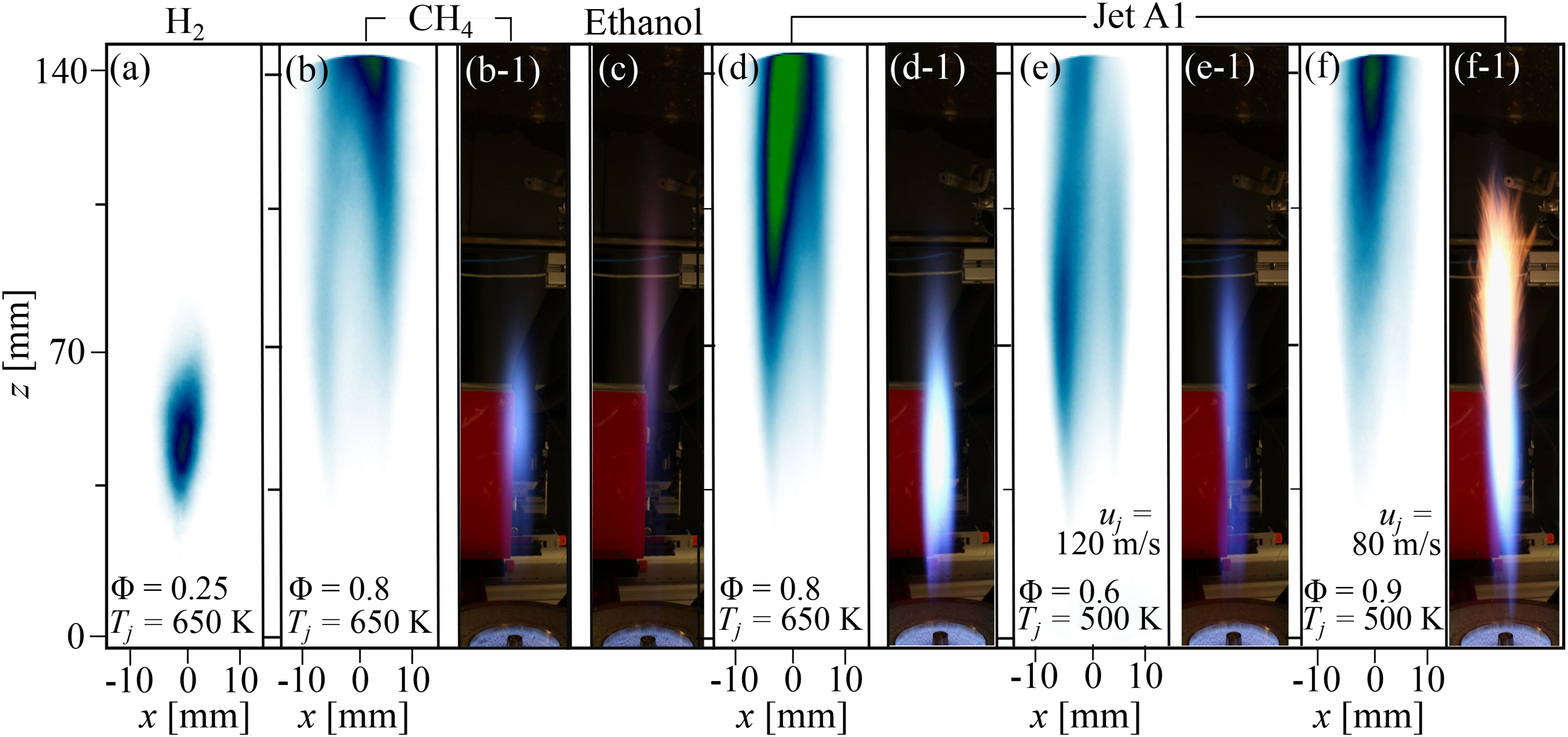
Figure 6 presents normalised and time averaged OH-chemiluminescence (CL) and direct images under representative operating conditions. Now, the entire spectrum of fuels, from H to Jet A1 is discussed. From the left-hand side, the H flame (a) displays a compact and axisymmetric OH distribution with maximum intensity at 47 mm, forming a bullet-shaped distribution for 120 m/s and 650 K at 0.25. For CH, as depicted in (b and b-1) with 120 m/s, the OH-CL signal is significantly elongated in the axial direction, flame anchoring in the wing due to hot gas entrainment and the flame root stretching up to 140 mm. The flame tip is excluded. For higher-carbon fuels, the ethanol flame is shown in (c) through a direct image captured at a lower 500 K with 0.4 g/s and 120 m/s. Even at a low 0.43, the flame is substantially elongated and exhibits weak reddish luminosity at the flame top. In contrast, the flame transitions back to a blue-dominant state for Jet A1 with 0.4 g/s under varying conditions of 650 K (d and d-1) and 500 K (e and e-1). Similar to the CH case, the bimodal radial OH-CL signal for Jet A1 originates near the nozzle’s radial wall side, indicating the flame stabilisation in the shear layer under various and conditions. This behaviour results from enhanced fuel/air mixing at the airblast edge due to the high shear forces as well as enhanced exhaust gas entrainment rates leading to flame stabilisation in the shear layer, as previously observed in conventional dual AB injectors.7,14,35 At lower jet velocities (f), the asymmetric radial OH-CL distribution becomes more pronounced and soot is formed at the flame tip, which can be attributed to larger droplet size distributions.
Normalised OH-CL and direct images for typical operating conditions with various fuel types. From left to right: (a) pure hydrogen flame under ultra-lean conditions ( 0.25) at 120 m/s and 650 K; (b, b-1) CH flame at 0.8, 120 m/s, and 650 K; (c) ethanol flame at 500 K with 0.4 g/s ( 0.38) and 120 m/s; (d–f) Jet A1 flames for different and conditions, with fixed at 0.4 g/s: 650 K for (d, d-1), 500 K for (e, f), 120 m/s for (e, e-1), and 80 m/s for (f, f-1).
The flame stabilisation and combustion process is further evaluated using the flame lift-off height (), the location of maximum OH-CL intensity () and the penetration length (), as shown in Figure 7. Panel (a) presents and trends with at low jet momentum ( 30 m/s and 300 K) for H and CH, while the Jet A1 flame is excluded due to direct ligament burning. Panel (b) shows the effect of under high jet momentum at 120 m/s for gaseous fuel flame with = 650 K and a Jet A1 direct injection jet flame at = 500 K. Panel (c) examines air preheating effects at 120 m/s and 0.2 for H and 0.8 for CH, with fixed at 0.4 g/s for Jet A1 while varying from 0.42 to 0.80. This difference arises because, for gaseous fuels, can be held constant while independently varying and , whereas for liquid fuels with fixed , changes in or inevitably alter as described in the ‘Operating conditions’ section. Lastly, panel (d) explores aerodynamic effects with constant for gaseous fuels and for Jet A1 ( = 0.28–0.56). Note that and for CH and Jet A1 flames are excluded due to elongated flame shapes, and ethanol is omitted because of weak CL signals and unstable pressure fluctuations. The corresponding averaged OH-CL images are presented in Figure S2 for H, CH, and Jet A1. The values for 350 K and 160 m/s could not be obtained due to extremely weak signal intensity. The elongated flame and its anchoring stability can be improved by introducing a low-swirl element to the coaxial airflow.21
Flame lift-off height, maximum intensity location, and penetration length against various (a and b), (c) and (d) for different fuel types; H, CH, and Jet A1. The symbols indicate mean values, while the bars represent the standard deviation. The colour x-axis notations in for (a and b), the blue-coloured axis indicates , , and for H, while red-coloured axis shows for of CH and Jet A1. The and values for CH and Jet A1 are excluded due to the elongated flame shape. Ethanol cases are also omitted because of the extremely weak CL signal and unstable pressure fluctuations.
For H at low jet momentum (panel (a)), increasing from 0.2 to 0.4 reduces from 108 to 85 mm while stabilising flame tip fluctuations () from 20 to 2.2 mm. A further increase in elongates the flame tail, as shown in Supplemental Figure S2 and also observed by Petry et al.44 decreases significantly with increasing . remains constant at an average 22 mm, while initially increases by 56 before being mitigated by 68. For CH, first increase up to = 1.0 followed by the modest reduction. Overall, in low jet momentum cases with marginal influence of hot entrainment from the pilot flame and a subsonic range for both fuels, the CH flame anchors at a slightly higher (averaging 27 mm) compared with H. This behaviour can be attributed to the substantially lower density ratio between the fuel and air streams ( for CH compared with for H), which exhibits weaker shear-layer growth and reduced turbulent-mixing rates.45 This occurs despite for CH being higher than for H at their respective under lean conditions, as shown in SMM Supplemental Figure S3(a). Under high jet momentum (panel (b)), and for H decrease slightly with increasing , while fluctuations are dampened and remains stable at 29 mm. For CH and Jet A1 flames, increases notably with , peaking at 36 mm for CH and 30 mm for Jet A1, while fluctuations () decrease by 85% between = 0.6 and 0.8. At low (300 K, panel (c)), the lean H flame at = 0.2 exhibits elongated structures and significant fluctuations, which diminish as increases, resulting in compact, stable flame shapes at 650 K. The CH flames maintain a relatively constant , with their fluctuations decreasing from 10.2 to 1.7 mm, a trend that is associated with an increase in the from 0.2 to 1.4 (see SMM Supplemental Figure S3(b)), whereas the Jet A1 flames exhibit an increase at 650 K. The latter can be attributed to pre-vapourisation at elevated temperatures, as discussed below, and the absence of locally fuel rich regions that favour advanced reaction onset. It is noteworthy that the robust trends, observed for onset at the nozzle edge in CH flames across various and conditions, indicate that the jet-stabilisation mechanism is strongly governed by exhaust gas entrainment. For aerodynamic effects (panel (d)), increasing slightly elongates and raises both and . H fluctuations decrease with , while CH and Jet A1 flames stabilise closer to the nozzle exit at higher velocities with larger fluctuations. This behaviour persists despite the for H remaining low ( 0.07) and the corresponding values for CH decreasing from 1.6 to 1.2, as shown in SMM Supplemental Figure S3(c). The difference between H and CH (and Jet A1) arises from the flame stabilisation location, either near the nozzle centreline or within the shear layer. The latter mechanism requires exhaust gas entrainment, the rate of which increases with . This contrast can be further interpreted in terms of the flow regime of each fuel jet. As discussed earlier, the H jets exhibit a high density ratio ( 10.5–14.4), which corresponds to a higher shear-layer growth rate ( 0.19–0.24) and a low Mach number (0.8). Here, is defined as 0.0825 , where is the velocity ratio between the jet velocity () and the estimated fuel exit velocity ().45 These conditions favour enhanced shear-layer development and promote turbulent fuel/air mixing. In contrast, CH jets possess substantially lower density ratios (1.32–1.81) and correspondingly reduced growth rates ( 0.15–0.16), while operating at Mach numbers exceeding unity. Under such supersonic conditions, compressibility effects are known to suppress turbulent transport and weaken mixing.45 Consequently, the H flame tends to anchor near the nozzle centreline with limited lift-off sensitivity, whereas the CH flame stabilises in the outer shear layer and depends more strongly on exhaust gas entrainment for ignition sustainment. Meanwhile, the pronounced variations in for Jet A1 with and are closely associated with the atomisation behaviour shown in Figure 5(c) and (d).
Pressure drop characteristics under fuel property and phase changes
The alternation of fuel properties and phase transition from liquid to gaseous, triggered by operating conditions such as fuel mass flow rate, air preheated temperature, and jet flow velocity, is directly coupled with injector performance, represented as pressure drop (P). Figure 8 illustrates the P across the µ-slit injector for various operating ranges and fuel types, as detailed in Table 1. Panel (a) presents the raw P as a function of gaseous mass flow rate for H, CH, and air at different preheated combustion air temperatures ranging from 350 K to 650 K. Based on separable specimen measurements,31 the µ-channel contributes about 67% of the total pressure loss for air flow test. For H flow, P exhibits a linear and steep slope with respect to mass flow rate across the operating conditions, whereas CH shows a lower P slope. The restricted operating range caused by heat transfer and compressibility effects can be mitigated by adjusting the fuel jet outlet diameters and their slit height, thereby enhancing fuel flexibility and scalability.31 The influence of is evident in air flow, where increasing from 350 K to 650 K enhances kinematic viscosity and flow velocity due to reduced density, leading to higher P values from 5.5 to 8.6 bar at 0.3 g/s. These changes in fluid properties are correlated with the ratios of temperature (), density (), and dynamic viscosity (), as depicted in Figure 8(b). Here, is the ratio of fuel inlet temperature () to air jet temperature (), accounting for fuel preheating effects across the injector system, while and represent the property ratios of inlet fluid to air at standard conditions, in order to normalise the effects of fuel properties. The correlation for the pressure ratio () with an exponential term of 0.57, defined as P relative to atmospheric pressure, is expressed as , where accounts for heat transfer from the heated Inconel wall to the fluid within the µ-slit channel. These exponents follow directly from rearranging the Darcy–Weisbach relation in combination with the Blasius friction factor, which yields the theoretical scaling of pressure drop with density and viscosity, consistent with turbulent pipe-flow behaviour.46 However, the slightly improved correlation at R = 0.98 obtained with non-linear scaling fit indicates the need to further consider the effects of relative roughness, form drag, and compressibility on gaseous fuel. This analysis is extended through an engineering correlation between the pressure drop relation, incorporating the discharge coefficient () with Mach number, against the thermal power as shown in Figure 8(c). The is defined as . The interpretation of is limited at the slit exit , although the local within the slit remains well below unity. The correlation shows excellent agreement ( = 0.99) for both H and CH, indicating that introducing a -based correction to capture compressibility effects, together with normalising the pressure loss with by the corresponding thermal power, provides a consistent scaling applicable to different gaseous fuels within the current µ-slit injector design.
Pressure drop (P) versus fuel mass flow rate () for gaseous (a–c) and liquid (d) fuel cases. Panel (a) presents the measured P against for H, CH, and air at various jet temperatures () and velocities (). Panel (b) shows the engineering correlation of the pressure ratio () as a function of the dimensionless parameters: temperature ratio (), density ratio (), and dynamic viscosity ratio (). Panel (c) illustrates the correlation between the discharge coefficient () and Mach number () with respect to thermal power (). Panel (d) on the right displays P for liquid fuels (Jet A1 and ethanol) under varying conditions.
Coming to the liquid fuels, ethanol shows a higher P of 9.3 bar at 0.3 g/s compared to 0.3 bar for Jet A1, with P increasing to 11.7 bar at 0.4 g/s. Raising to 350 K reduces P for ethanol to 5.5 bar at 0.3 g/s due to lower viscosity and surface tension, yet further a increase of to 500 K raises P significantly to 13.4 bar, indicating liquid evaporation within the slit, given that the boiling point of ethanol is 351 K. For Jet A1, P remains below 0.5 bar across all fuel mass flow rates at 500 K. However, elevating to 650 K induces higher P due to liquid pre-vapourisation, peaking at 2.8 bar at 0.3 g/s before decreasing with further increase in , indicating ongoing vapourisation as shown in Figure 5(c). The low P trends observed for Jet A1 underscore the exceptional atomisation performance of the µ-slit injector, which achieves fine droplet and uniform radial distribution via its extremely narrow slit, yet large effective exit area. This excellent operational flexibility and dynamic response position it as a promising injection concept for integration across a wide range of industrial applications, including gas and oil burners, heating systems, MGTs, and future hybrid aero-engine systems. Nevertheless, heat transfer induced changes in fuel properties and potential phase alteration, together with surface roughness effects, require further assessment and remain under investigation.
Conclusions
The novel AM µ-slit fuel injector is experimentally evaluated over a wide operating condition, including variations in jet velocity, fuel loading, pre-heated air temperature, and fuel type. The micro-scale injection gap produces excellent atomisation and homogeneous fuel placement for liquids, while the large overall exit area yields a low pressure drop, enabling direct gaseous-fuel injection through the same hardware without geometric modification. Combustion behaviour for H, CH, ethanol, and Jet A1 shows stable operation across both low- and high-momentum jet regimes. H flames exhibit excellent stability in the compact jet flame, whereas CH and Jet A1 display similar lift-off trends, primarily governed by fuel/air mixing in the shear layer and exhaust gas entrainment, indicating that flame stabilisation is dominated by turbulence–chemistry interactions and influenced by auto-ignition. Pressure drop correlations align with engineering expectations for gases, while liquid-fuel operation shows non-monotonic behaviour linked to pre-vapourisation effects. Overall, the AM µ-slit injector demonstrates exceptional operational and fuel flexibility, offering unprecedented scalability and adaptability. These attributes make it highly attractive for industrial burners, stationary and MGTs, and future hybrid aero-engine systems. Its geometric simplicity and prefilming-free design further position it as an ideal platform for model validation and continued development through numerical studies for both gaseous and liquid fuels. Future work will focus on integrating real combustor features and performing detailed scalar analyses using advanced two-dimensional laser diagnostics to evaluate emissions further and generate high-fidelity data sets for model development and numerical simulation.
Supplemental Material
sj-pdf-1-scd-10.1177_17568277251408296 - Supplemental material for Pushing fuel flexibility with AM μ-slit injector for jet-stabilised combustion
Supplemental material, sj-pdf-1-scd-10.1177_17568277251408296 for Pushing fuel flexibility with AM μ-slit injector for jet-stabilised combustion by Yeonse Kang, Basil Jose and Fabian Hampp in International Journal of Spray and Combustion Dynamics
Supplemental Material
sj-pdf-2-scd-10.1177_17568277251408296 - Supplemental material for Pushing fuel flexibility with AM μ-slit injector for jet-stabilised combustion
Supplemental material, sj-pdf-2-scd-10.1177_17568277251408296 for Pushing fuel flexibility with AM μ-slit injector for jet-stabilised combustion by Yeonse Kang, Basil Jose and Fabian Hampp in International Journal of Spray and Combustion Dynamics
Supplemental Material
sj-pdf-3-scd-10.1177_17568277251408296 - Supplemental material for Pushing fuel flexibility with AM μ-slit injector for jet-stabilised combustion
Supplemental material, sj-pdf-3-scd-10.1177_17568277251408296 for Pushing fuel flexibility with AM μ-slit injector for jet-stabilised combustion by Yeonse Kang, Basil Jose and Fabian Hampp in International Journal of Spray and Combustion Dynamics
Supplemental Material
sj-pdf-4-scd-10.1177_17568277251408296 - Supplemental material for Pushing fuel flexibility with AM μ-slit injector for jet-stabilised combustion
Supplemental material, sj-pdf-4-scd-10.1177_17568277251408296 for Pushing fuel flexibility with AM μ-slit injector for jet-stabilised combustion by Yeonse Kang, Basil Jose and Fabian Hampp in International Journal of Spray and Combustion Dynamics
Footnotes
Acknowledgements
The authors acknowledge the funding by the Deutsche Forschungsgemeinschaft (DFG, German Research Foundation) – project number: 456687251. Many thanks to the Institute for Machine Tools (IfW), University of Stuttgart, who manufactured the injection systems. Support from the German Aerospace Center (DLR) Stuttgart, the Stuttgart Center for Simulation Science (SimTech) is also gratefully acknowledged.
ORCID iDs
Yeonse Kang
Basil Jose
Fabian Hampp
Funding
Funding was provided by the Deutsche Forschungsgemeinschaft (DFG, German Research Foundation) - project number: 456687251.
Declaration of conflicting interest
The author(s) declared no potential conflicts of interest with respect to the research, authorship, and/or publication of this article.
Supplemental material
Supplemental material for this article is available online.
References
1.
ShijieL. Research on data center load simulation and optimization of integrated energy system. AIP Adv2025; 15: 085003.
2.
WeerakoonASAssadiM. Generalized framework for micro gas turbine techno-economic assessment. Energy Conver Manag2024; 316: 118820.
3.
BoukhanoufR. Small combined heat and power (CHP) systems for commercial buildings and institutions. In: Beith R (ed.) Small and Micro Combined Heat and Power (CHP) Systems, 2011. pp.365–394. Woodhead Publishing Series in Energy, Woodhead Publishing.
4.
MoliéreM. The fuel flexibility of gas turbines: a review and retrospective outlook. Ener2023; 16: 3962.
5.
HuthMHeilosA. Fuel flexibility in gas turbine systems: impact on burner design and performance. In: Sakai Y and Vassilicos C (eds.) Modern Gas Turbine Systems, 2013. Woodhead Publishing.
6.
LammelOSeverinMAxHet al.High momentum jet flames at elevated pressure, A: experimental and numerical investigation for different fuels. Proc ASME Turbo Expo2017; GT2017.
7.
HamppFSchäferDLammelO. Spray flame characterization of a duel injector for compact combustion systems. Comb Sci Tech2023; 197: 463–496.
8.
RaveeshMXuLDominguezAet al.Characteristics of mild combustion of CH4-CO2 jets in a piloted burner – laser-diagnostic and LES studies. Combust Flame2025; 273: 113955.
9.
YangNXiongYLiuZet al.Reaction zone structure and stability of lifted hydrogen flames in a MILD model combustor equipped with dual-coaxial-jet nozzles. Int J Hydrogen Energy2025; 145: 1071–1083.
10.
LingstädtTGrimmFDrudeAet al.Numerical investigation of a jet-stabilized combustion system operated with low-calorific SOFC off-gas. AIAA2019; 2019–1675.
11.
LammelOStöhrMKutnePet al.Experimental analysis of confined jet flames by laser measurement techniques. J Eng Gas Turbines Power2012; 134: 041506.
12.
LammelORödigerTStöhrMet al.Investigation of flame stabilization in a high-pressure multi-jet combustor by laser measurement techniques. Proc ASME Turbo Expo2014; GT2014.
13.
HamppFGounderJDAxHet al.High momentum jet flames at elevated pressure, E: quantification of droplet size distribution and transport. Proc ASME Turbo Expo2020; GT2020.
14.
SchäferDGounderJDLammelOet al.High momentum jet flames at elevated pressure, D: simultaneous measurements of OH/PAH PLIF and mie scattering on liquid fuels. Proc ASME Turbo Expo2019; GT2019.
15.
LückerathRMeierWAignerM. FLOX® combustion at high pressure with different fuel compositions. J Eng Gas Turbines Power2008; 130: 011505.
16.
WeberRSmartJPKampWvd. On the mild combustion of gaseous, liquid, and solid fuels in high temperature preheated air. Proc Combust Inst2005; 30: 2623–2629.
17.
YeJMedwellPRVareaEet al.An experimental study on mild combustion of prevaporised liquid fuels. Appl Energy2015; 151: 93–101.
18.
LuhmannHMaldonadoFCSpörlRet al.Flameless oxidation of liquid fuel oil in a reverse-flow cooled combustion chamber. Energy Procedia2017; 120: 222–229.
19.
ArghodeVKKhalilAEEGuptaAK. Fuel dilution and liquid fuel operational effects on ultra-high thermal intensity distributed combustor. Appl Energy2012; 95: 132–138.
20.
KimHParejaJLammelO. Effects of a 3D-printed atomizer component on fuel-spray and flame characteristics of a jet-stabilized compact gas turbine combustor fed with liquid fuels. J Eng Gas Turbines Power2024; 146: 121020.
21.
KangYAhnJHamppF. Low swirl effect on compact spray and combustion systems using additive manufactured dual airblast injectors. J Eng Gas Turbines Power2024; 146: 121001.
22.
HoffmannSKochRBauerH. Reacting flow prediction of the low swirl lifted flame in an aeronautical combustor with angular air supply. Proc ASME Turbo Expo2023; GT2023.
23.
IzadiSZangerJBaggioMet al.Experimental investigation of the effect of superheated liquid fuel injection on the combustion characteristics of premixed lean flames. J Eng Gas Turbines Power2024; 146: 051012.
24.
GiulianiFPaulitschNCozziDet al.An assessment on the benefits of additive manufacturing regarding new swirler geometries for gas turbine burners. Proc ASME Turbo Expo2018; GT2018.
25.
RajasegarRMitsingasCMMayhewEKet al.Development and characterization of additive-manufactured mesoscale combustor array. J Energy Eng2018; 144: 04018013.
26.
KimSKimJByunHet al.Development of a novel hydrogen burner using additive manufacturing. Proc ASME Turbo Expo2024; GT2024.
27.
DurocherAFanLFrancoliniBet al.Characterization of a novel additive manufacturing micromix nozzle burning methane to hydrogen. J Eng Gas Turbines Power2024; 146: 051009.
28.
GuddatiSKiranASKLeavyMet al.Recent advancements in additive manufacturing technologies for porous material applications. Int J Adv Manuf Technol2019; 105: 193–215.
29.
CrayfordALacanFRunyonJet al.Manufacture, characterization and stability limits of an AM prefilming air-blast atomizer. Proc ASME Turbo Expo2019; GT2019.
30.
AdamouAKennedyIFarmerBet al.Experimental and computational analysis of an additively manufactured vaporization injector for a micro-gas turbine. Proc ASME Turbo Expo2019; GT2019.
31.
KangYSeidlerJAhnJet al.AM micro-structures with bespoke permeability. Int J Heat Mass Transf2024; 241: 126674.
32.
GebisaAWLemuHG. Additive manufacturing for the manufacture of gas turbine engine components: literature review and future perspectives. Proc ASME Turbo Expo2018; GT2018.
33.
PereiraTKennedyJPotgieterJ. A comparison of traditional manufacturing vs additive manufacturing, the best method for the job. Procedia Manuf2019; 30: 11–18.
34.
CroceGD’AgaroPFilippoA. Compressibility and rarefaction effects on pressure drop in rough microchannels. Heat Transf Eng2007; 28: 688–695.
StrakyPATalleyDGSankarSVet al.Phase-Doppler interferometry with probe-to-droplet size ratios less than unity. II. Application of the technique. Appl Opt2000; 39: 3887–3893.
42.
LefebvreAHMcDonellVG. Atomization and sprays. 2 ed. Boca Raton: CRC press, 2017, ISBN 978-1-4987-3625-1.
43.
KangYHamppF. Additive manufactured µ-slit injector for high momentum jet-stabilised combustion system. Proc Med Combust Symp2025; 13: 14.
44.
PetryNMannazhiMYinZet al.Investigation of fuel and load flexibility of an atmospheric single nozzle jet-stabilized flox combustor with hydrogen/methane-
air mixtures. J Eng Gas Turbines Power2024; 146:
061004.
45.
McGuirkJJFengT. The near-field aerodynamic characteristics of hot high-speed jets. J Fluid Mech2021; 915: A120.
46.
WhiteFM. Fluid Mechanics. 7 ed. New York: McGraw-Hill Education, 2011, ISBN 9780077422417.
Supplementary Material
Please find the following supplemental material available below.
For Open Access articles published under a Creative Commons License, all supplemental material carries the same license as the article it is associated with.
For non-Open Access articles published, all supplemental material carries a non-exclusive license, and permission requests for re-use of supplemental material or any part of supplemental material shall be sent directly to the copyright owner as specified in the copyright notice associated with the article.