
Abstract
The planar laser induced hydroxyl fluorescence (OH-PLIF) technique was used to study three kinds of swirling flame, namely flames I, II, and III, by changing swirl conditions. According to the PLIF results, double structure exists in flames I and II. The inner flame burns in the inner shear layer and is anchored by vortex breakdown, which is similar to the M- or V-shaped flame. The unique outer flame is attached to the inner wall of the air annular nozzle and burns in the outer shear layer. The lean blowout (LBO) equivalent ratio of swirling flame with outer flame is lower than that without outer flame. It is interesting to compare the LBO mechanisms among the three types and the traditional swirling flame, and investigate their unsteady characteristics. Firstly, the flameout process of flames I and II starts from the local extinguishing at the root of the outer flame. However, the LBO process of flame III is consistent with that of traditional swirling flame, that is, it starts with repeated extinguishing and reigniting at the root of the inner recirculation zone (IRZ). Secondly, the unsteady characteristics of the three flames are analyzed by spectral proper orthogonal decomposition. It is found that flame oscillations, asymmetric disturbances, and longitudinal disturbances of different frequencies exist in different combinations under near-LBO conditions. In particular, asymmetric and P-wave disturbances mainly exist in the inner shear layer and jet breaking down, which further indicates the stability and anti-LBO potential of the outer flame.
Introduction
With increasingly stringent emission requirements, gas turbines need to run under lean fuel conditions stably. 1 Modern gas turbine engines mainly induce vortex breakdown through swirling flow to achieve aerodynamic stability of turbulent flame. 2 When the strength of the swirl is sufficient, the axial velocity profile of the swirl jet changes from a Gaussian distribution to a wake profile, that is, a backflow zone is generated in the central region. 3 However, fluctuation of fuel-air mixing induced by swirling flow will lead to flameout under lean conditions. 4 With the development of experimental methods with high spatial and temporal resolution, studies on flameout characteristics and dynamics are increasingly abundant.5–9
The flameout characteristic of swirling flame is subject to many factors. Rock et al. performed an experimental study on the near lean blow-off dynamics of spray flame in Georgia Tech spray combustor. 10 The results show that the blow-out event of the combustion system with recirculation is the culmination of several intermediate processes. Lean blowout (LBO) precursor events are firstly identified, that is, spray flame experiences local extinction, reignition, and recovery frequently. As a precursor to LBO, local extinction of non-premixed flame has been studied extensively. High scalar dissipation rate is considered as the governing factor. 11 Particularly, a high strain rate will lead to flameout under the conditions far beyond LBO in swirling non-premixed flame. 12 Li et al. studied strain-induced extinction, fuel-lean extinction, and fuel-rich extinction, respectively, by using theory and large eddy simulation. 13 Davide et al. investigated the flameout characteristics of premixed, non-premixed, and spray combustion based on Cambridge bluff-body swirl burner 7 which has an outer flame attached to the bluff body edges. When gradually approaching to blowout, the frequency of holes along the outer flame sheet is increasing for gaseous non-premixed flame. The non-premixed shows a random occurrence of lift-off, which is further evidence of local extinction. Yuan et al. conducted spray combustion experiments on a Cambridge bluff-body swirl burner and analyzed the LBO characteristics of four liquid fuels with different validities. 14 The flame has double structures, namely the inner flame along the spray cone and the outer flame attached to the corner of the blunt body. Occasionally, when it was close to LBO, the inner flame almost completely disappeared and the outer flame was severely broken. In addition, low-volatile fuels have deeper spray penetration and higher lift-off height.
The interaction between flame and coherent structure in swirling flow field plays an important role in the stability and dynamics behavior of swirling flame. Precessing vortex core (PVC) is a common large-scale coherent structure15,16 in a swirling flow field, which usually appears as an asymmetric mode with circumferential wave number m = 1, and sometimes a double helix feature of m = 2. According to the velocity distribution characteristics around PVC, it is divided into the vortex core region and the external region. 17 The circumferential velocity is proportional to the radius in the vortex core region, while not in the external region. The strain rate in the external region is thus high that can lead to convective mixing of flame, 18 but sometimes causes local extinguishing.19,20 The ability of PVC to promote mixing not only acts on fuel and air, but on high-temperature gas and unburned low-temperature gas. 21 At lean conditions, the rapid mixing of high-temperature gas and low-temperature gas may cause the flameout of the non-premixed flame. 22 In addition, many researchers have found that PVC are suppressed in some reactive flow fields.23–27 Studies 28 show that PVC can generally exist in the flow field with a detached M-shaped flame, and disappear in the flow field with attached V-shaped flame. The reason is that the V-shaped flame attached to the nozzle of the swirler results in high radial density gradient in the flame root, and the PVC is then inhibited by the baroclinic torque.
When it is close to lean flameout, the dynamic characteristics of flame oscillations are closely related to PVC. As shown in reference, 28 M-shaped flames with PVC always form at lower equivalence ratios and are inhibited at higher equivalence ratios, which shows that the flame is susceptible to PVC when the flame is near flameout. By studying the V–M transformation mechanism of swirling flame, Stöhr et al. 29 found that the M-shaped flame indicates the presence of PVC, which is frequently accompanied by thermoacoustic instability. Meier et al. 30 carried out an experimental study on the thermoacoustic instability of swirling flame. He found that the flame root located in inner recirculation zone (IRZ) reveals obvious oscillating behavior through phase averaging analysis. German Aerospace Center (DLR) has conducted research on a dual-swirl burner 4 and found that the combustion reaction mainly occurred in two regions, namely the spiral region along PVC and the flame root near the lower stagnation point in IRZ. The combustion products in the spiral region supply energy through IRZ to the flame root, while the flame root is the source of heat and free radicals of helix region. Flame root is fragile due to the presence of high strain rates. Even in a stable state, flame root continually experiences extinction and reignition. When near LBO, the frequently extinction and re-ignition process is more prominent. This is essentially caused by PVC. Therefore, it is possible to reduce the LBO limit to a lower level by changing the flow field or mixture fraction distribution in the flame root area. It is illustrated by an earlier study about active control. 31 The study realized the active control of LBO by redistributing the distribution of fuel entering the combustor between the main flow and small pilot combined with the detecting of flameout precursor. In this paper, by inducing flow separation in the inner wall of the outer (or secondary) swirler nozzle, a stable combustion flame is formed, which also has the potential to reduce the LBO limit. This is different from the outer flame developed from bluff-body in the reference, 14 and has little influence on flame root flow field in IRZ. Therefore, this paper provides a new idea for the control of LBO in swirl combustor.
This study extends the previous work 32 by comparing the flame dynamics from equivalent ratio 0.8 to flameout under different swirler parameters. High-speed planar laser induced hydroxyl fluorescence (OH-PLIF) technology was applied to experimental research on the dynamic characteristics of non-premixed swirling flame. The flame morphology with double structure, inner flame and outer flame, is introduced. The first purpose of this work is to demonstrate that the outer flame attached to the inner wall of the air annular nozzle has the potential to improve the performance of LBO limit. The lean flameout characteristics and mechanisms are analyzed. As the lean flameout condition approaches, self-excited oscillation of the swirl flame occurred. Thus, the dynamic characteristics of flame oscillations are then studied by spectral proper orthogonal decomposition (SPOD). Based on the results of modal decomposition, three unsteady characteristics and their frequencies were researched.
Experimental setup
Combustor
The burners shown in Figure 1(a) were constructed with reference to the DLR's dual-swirl gas turbine model combustor geometry by Meier et al.6,33 Dry air at ambient temperature enters the plenum (diameter 72 mm, height 57.5 mm) and then separately passes the primary and secondary (Figure 1(b)) radial swirl generator. The two counter-swirling flows enter the combustion chamber through a central circular nozzle (diameter 14.4 mm) and a surrounding annular nozzle (inner diameter 17.6 mm, outer diameter 27 mm contoured to an outer diameter of 30 mm). CH4 is supplied through an annular slit between the air nozzles. The combustion chamber has a square cross-section of 85 × 85 mm2, a height of 117 mm, and is enclosed by four quartz windows held by four square pillars (11 × 11 mm2) in the corners allowing optical access. A conical top plate with a central exhaust tube (diameter 36 mm, length 40 mm) forms the exit.
(a) Schematic of dual-swirl combustor and (b) the structure and parameters of swirlers.
Compared with the burners of DLR, the following structural characteristics researched in this study are noteworthy. First, the exit planes of the fuel and central air nozzles are at the same height with the secondary air nozzle. Second, the gas enters the combustion chamber through annular crack, rather than 72 channels with square sections. Changes in the gas passage make a significant difference in the flame structure, which will be discussed in detail below. In addition, the spins of the two-stage swirlers are opposite. Two groups of primary and secondary swirlers are designed, namely A1, A2 and B1, B2, respectively, including three combinations, as shown in Table 1. The three combinations studied in this paper are shown in Table 1.
Parameters of swirlers for three burners.
The swirl number, 
As shown in Table 2, the experiment was carried out at three sets of airflow rates, which were 110, 174, and 232 g/min, respectively. The swirling flames from stable to near flameout were obtained by adjusting the methane flow rate while the airflow rate was kept constant. The maximum global equivalent ratio of each group experiment was set at about 0.8, and the methane flow was gradually reduced with a step size of about 0.1. While for near LBO, the step size is reduced to about 0.02 until the global extinction.
Flow conditions used for experiments.
The high-speed OH-PLIF was used to visualize the flame structure. Nd:YAG laser is independently developed by the National Key Laboratory of Science and Technology on Tunable Laser of Harbin Institute of Technology. It produced a laser with a single pulse energy of 30 mJ and wavelength of 532 nm. The repetition frequency was 1 kHz. The dye laser (Sirah Credo) was pumped to obtain a UV pulse with a wavelength of 283.553 nm and a single pulse energy of 1.6 mJ. The laser beam was converted into a light sheet of nearly 7 cm through the sheet forming optics to cover the main upstream area of the swirl flame. The light sheet was shot vertically into the quartz glass window of the burner and excited the OH A-X band. The fluorescence signal is collected by an intensified CMOS camera (1856 × 970 pixel) at a sampling frequency of 1 kHz. The acquisition area was shown in the red dotted box in Figure 1(a), with a height of about 67 mm. The experimental system thus achieved a spatial resolution of approximately 72 µm per pixel. More details about the high-speed OH-PLIF system can be found in Cao et al. 32
Results
Morphology of swirling flame
The swirling flames can be grouped into three types according to the structure, namely flames I, II, and III. Figure 2 shows the OH-PLIF time-averaged and instantaneous images of the three swirling flames. A unique double structure exists in flames I and II. The inner flame burns in inner shear layer and is anchored by vortex breakdown region, which is similar to the M- or V-shaped flame.5,6,35 The unique outer flame is attached to the inner wall of the secondary swirler nozzle and burns in outer shear layer. The inner flame of flame I is M-shaped, basically connected or occasionally disconnected from the outer flame, which is reflected in the signal strength at 10 mm above the nozzle in the averaged figure compared with other heights. While the inner one is V-shaped and is basically disconnected from the outer in flame II. Yuan et al. 14 also described the existence of outer flame in the Cambridge bluff-body swirl burner. However, the outer flame described in this study can be identified as a result of flow separation, while the one in reference is attached to bluff body. As for flame III, the outer flame disappears and the flame even propagates to the upstream wall along the outer recirculation zone (ORZ).
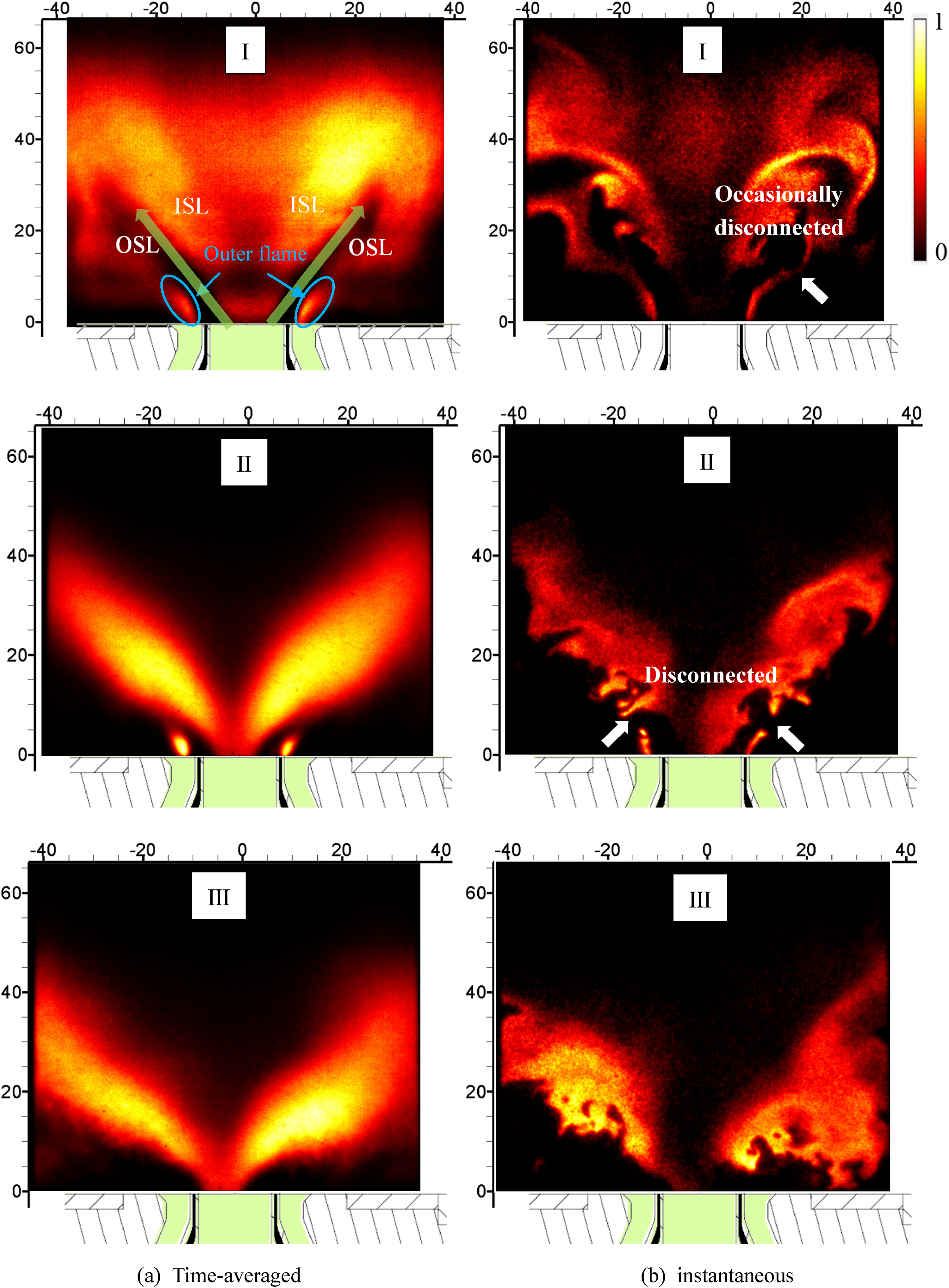
Time-averaged and instantaneous OH-PLIF swirling flame. I
It can be found that the conditions of II and III are similar. In fact, this is because the flame morphology changes after the methane flow rate are slightly reduced. During the experiment, the flame of A2-B1 always shows the characteristics of I. While the flame of A1-B2 is most likely to change from II to III, and it occurs at high airflow. In other words, the outer flame is more stable when the primary swirler is weakened, but it is more likely to disappear when the secondary swirler is weakened.
When the air is 174 g/min, the conversion between flame II and flame III is captured at near-LBO in burner A1-B2. In the PLIF results of a given 1 s, flame II was observed during 1 ms—38 ms and 245 ms—1000 ms, and flame III was observed during 45 ms—217 ms. The conversion process from II to III between 38 and 45 ms is shown in Figure 3. It can be found that the inner flame of flame II is V-shaped and propagates downstream along the shear layer at a specific cone Angle. However, when the outer flame stabilized by separation region disappeared, the flame changed from II to III, and then its spread path changed to be radially outward, even into the ORZ and propagated upstream (116 ms).
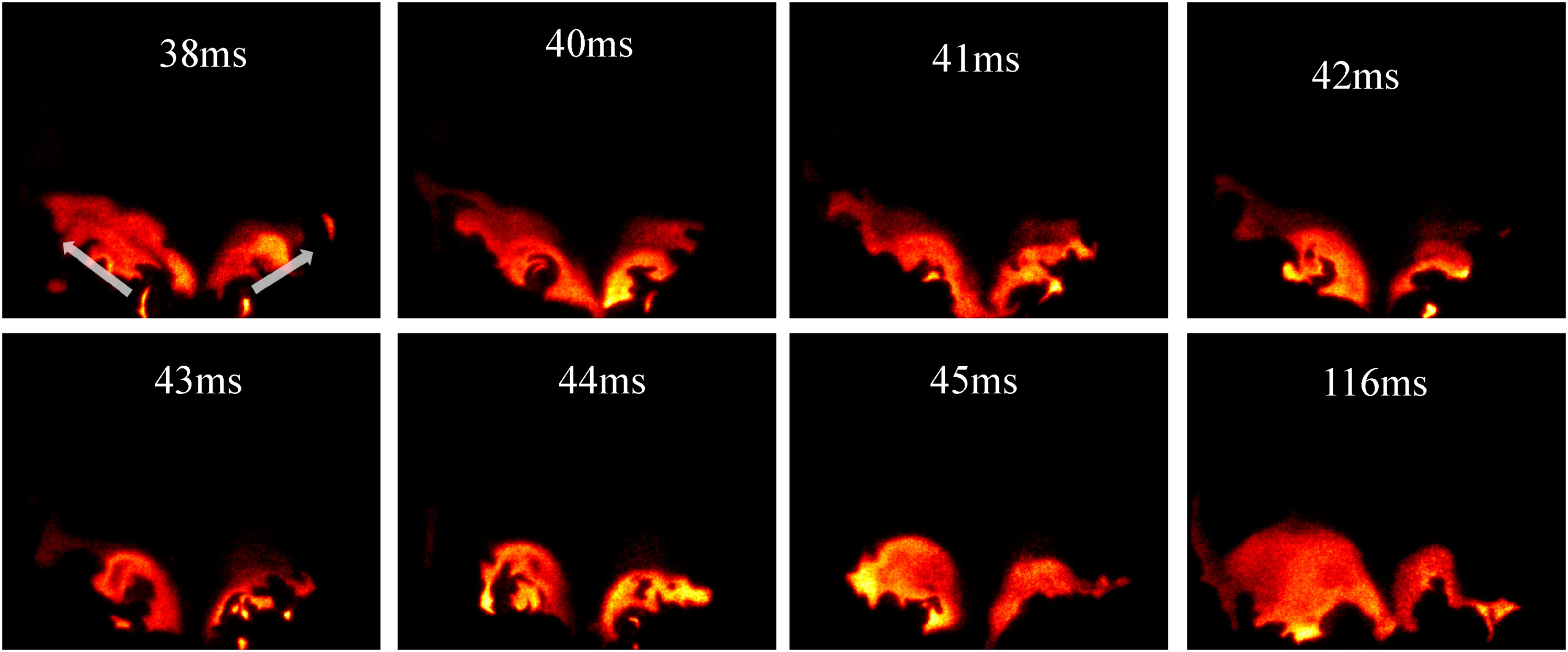
The transition process from flame II to Flame III,
For the DLR burner designed by reference in this paper, Weigand et al. 5 also investigated three kinds of flame, namely flames A, B, and C, which were found to be related to the flame in this paper. In particular, the structure of flame III in this paper is similar to that of flame B. In addition, because of the existence of the outer flame, the flame I in this paper is similar to flame A, but there are also differences. The outer flame in this paper develops from the inner wall of the annular nozzle of the airflow, while the one of flame A extends to the outer wall. Chen et al.19,20 showed that the outer flame of flame A was due to the fuel being captured by ORZ. However, it is more likely that a stable flow separation occurs at the inner wall of annular nozzle, and the fuel is trapped in the separation zone and ignited to form an outer flame.
Figure 4 shows averaged and instantaneous images near-LBO in burner A1-B1, corresponding to airflow rate of 110, 174, and 232 g/min, respectively. The time-average results show that the lower the airflow rate is, the weaker the flame in the vortex breakdown area becomes and the more prominent the flame branch in the separation area is when approaching LBO, which is similar to reference. 14 Interestingly, the outer flame lift-off was not observed, which is quite different from the reference. 14 As can be seen from the transient results, the flame at vortex breakdown area is difficult to maintain at near-LBO. It can be concluded from the transient results that when close to LBO, the inner flame stabilized by vortex breakdown is constantly changing at a large spatial scale, while the outer flame is relatively stable. In addition, the local extinguishing is obviously in inner flame, while is rarely in the outer flame. The above analysis shows that the outer flame can provide a steady heat source for the swirling combustion.
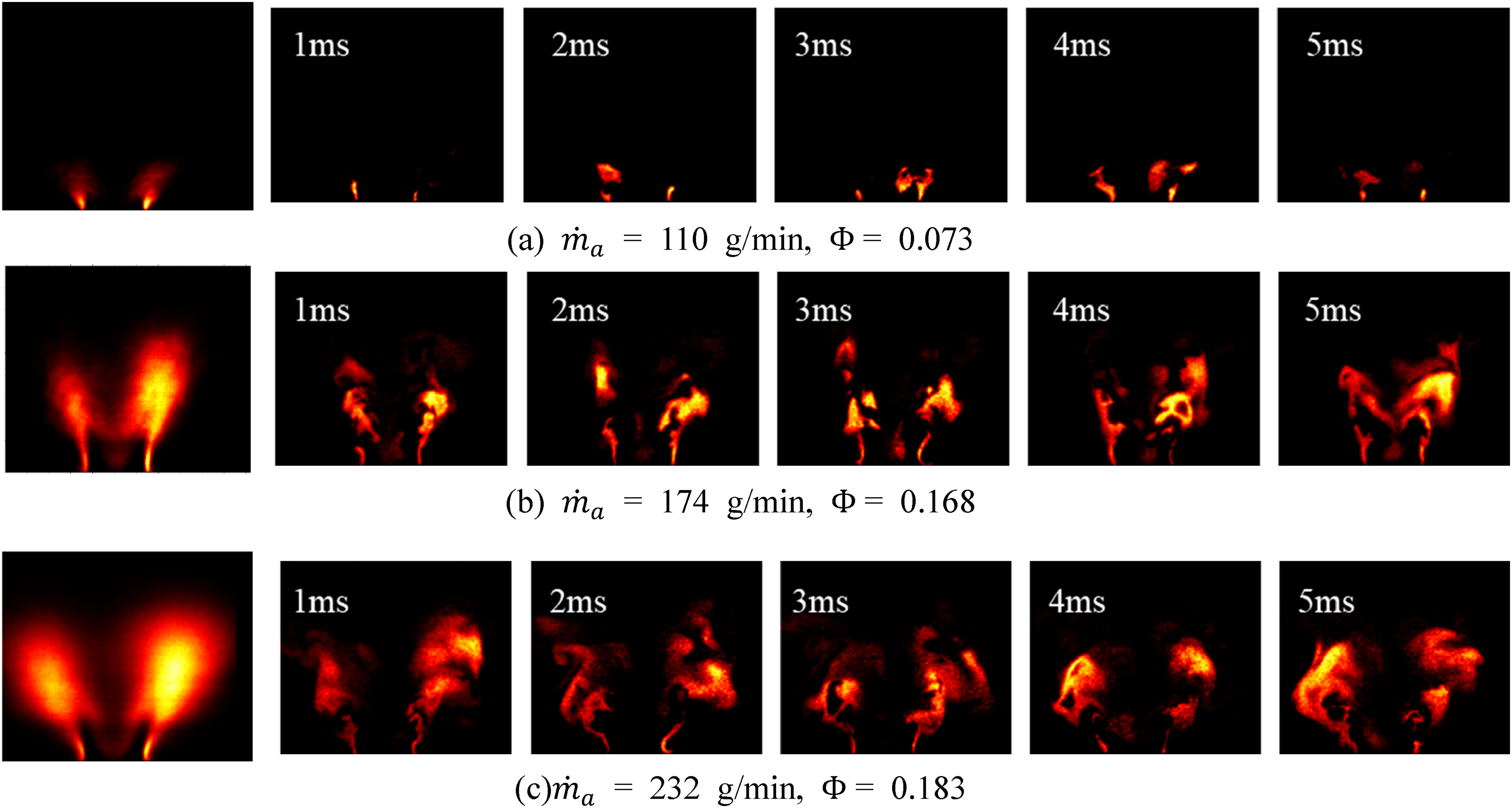
Averaged and corresponding instantaneous OH-PLIF results near-LBO at three different
Figure 5 shows averaged OH-PLIF images near-LBO and the equivalent ratio curve of three burners. It can be identified from Figure 5 (right) that the near-LBO equivalent ratio of the three burners is similar when
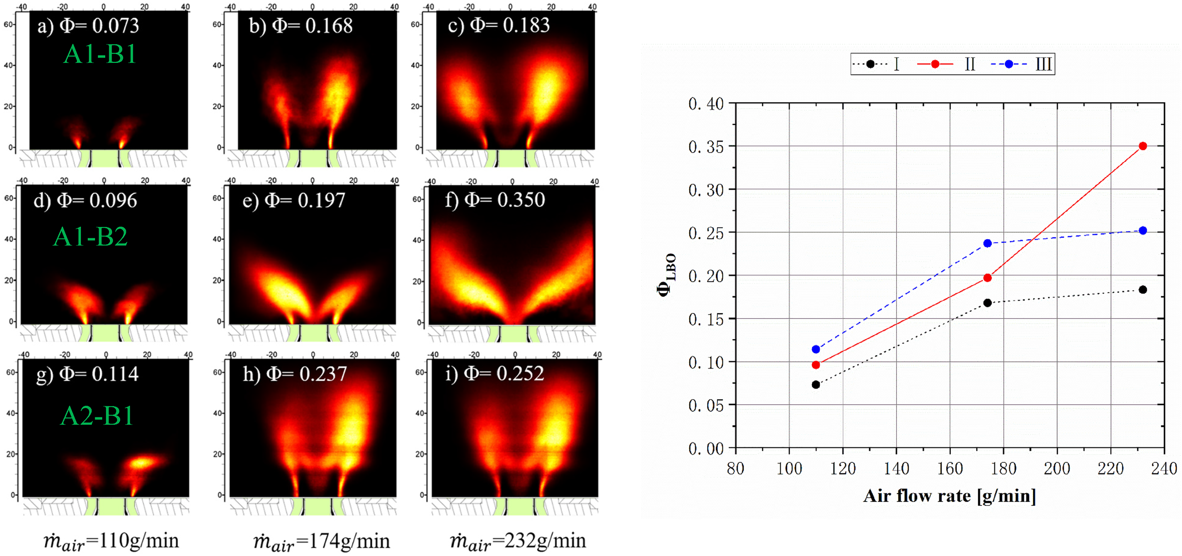
Averaged OH-PLIF images near-LBO of three burners under different
Figure 6(a) shows the flameout process of flame III in burner A1-B2 while Figure 6(b) shows the process of flame I which outer flame. The inner flame root (marked with square white boxes) of flame III experienced the process of extinction and reignition in 0 ∼ 39 ms, and even led to the disappearance of the flame on the right side of the measurement plane (21 ms). At 49 ms, the flame root extinguished again. The subsequent reigniting failed, however, which resulted in a global flameout. Figure 6(b) shows the flameout process of flame I in the presence of the outer flame, which is also caused by the disappearance of the outer flame root (marked with white arrows). In 0 ∼ 10 ms, the flame root on the left side is extinguished and reignited, and in 10 ∼ 17 ms, the flame root on the right side is disappeared and reignited. When the flame root is extinguished, the downstream flame gradually disappears. At 158 ms, extinguishing occurred again on the right side of the flame root and failed to be reignited, resulting in global flameout. The flameout process is very different for the presence and absence of outer flame. When absent, flameout arises from instability at the root of the inner flame, which is consistent with Stöhr et al. 4 When outer flame present, it is difficult for the IRZ to keep the swirling flame burning steadily under the condition of near LBO. The factor that promotes the formation of outer flame (perhaps flow separation) becomes the main way to stabilize flame. Flameout originates from the instability of the root of outer flame, and the extinguishing and reignition of the outer flame root can be regarded as the precursor event of the global flameout.
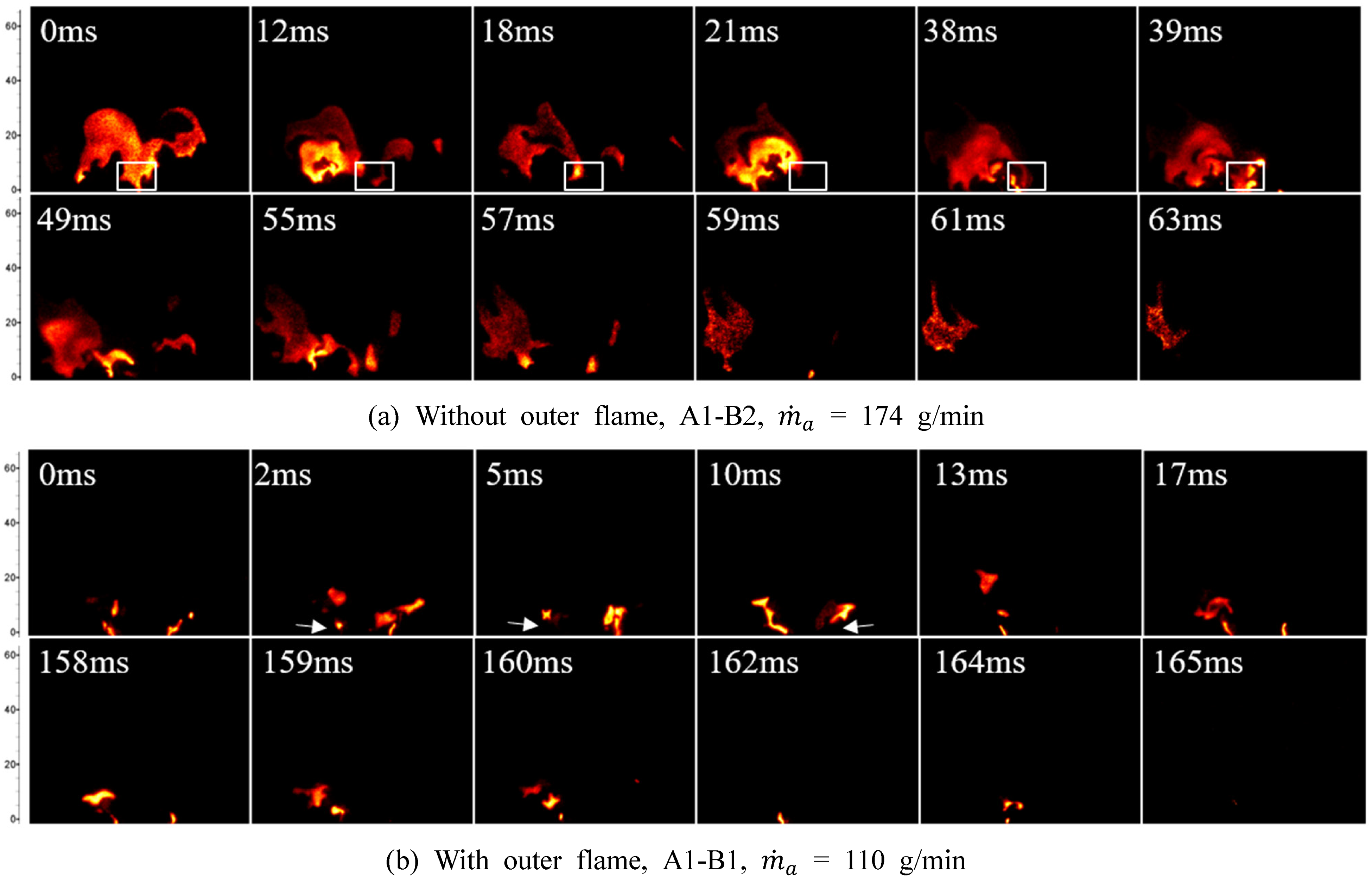
Time series of flame extinguishing in the absence (a) and presence (b) of the outer flame.
1) Fourier analysis
In order to investigate the oscillation characteristics of swirling flame, the frequency domain information of the luminescent intensity pulsation of flame light-in-sight is obtained by Fourier transform. The gray matrix of each image was summed to obtain the area integrated values
7
to characterize the heat release intensity of flame in the measured plane. Then the fast Fourier transform (FFT) is applied to the time series of integral values to obtain the spectrum. For OH-PLIF results of each working condition, 1000 images were selected. The results indicate that the swirling flame oscillates at about 200 Hz and only occurs under near-LBO conditions with an airflow rate of 110 g/min. Figure 7 shows the spectrum results of three burners from stable to near-LBO at airflow rate of 110 g/min. It should be noted that the frequency of all three burners is about 200 Hz, indicating that the occurrence of self-excited oscillation is not dominated by swirling conditions. In addition, the self-excited oscillation of the flame appears in conditions near-LBO. The local equivalent ratio in reaction region is thus more sensitive to the disturbance and excitation, but the identification of disturbance source or excitation source needs to be further explored through the investigation of flow field and other information in the future. In addition, limited by the PLIF technology and the sampling frequency of 1 kHz, it is necessary to adopt a measurement technology with a higher sampling frequency to comprehensively and carefully study the combustion instability in future work.
Spectra of the area integrated of OH concentration in the measured plane. 2) Modal analysis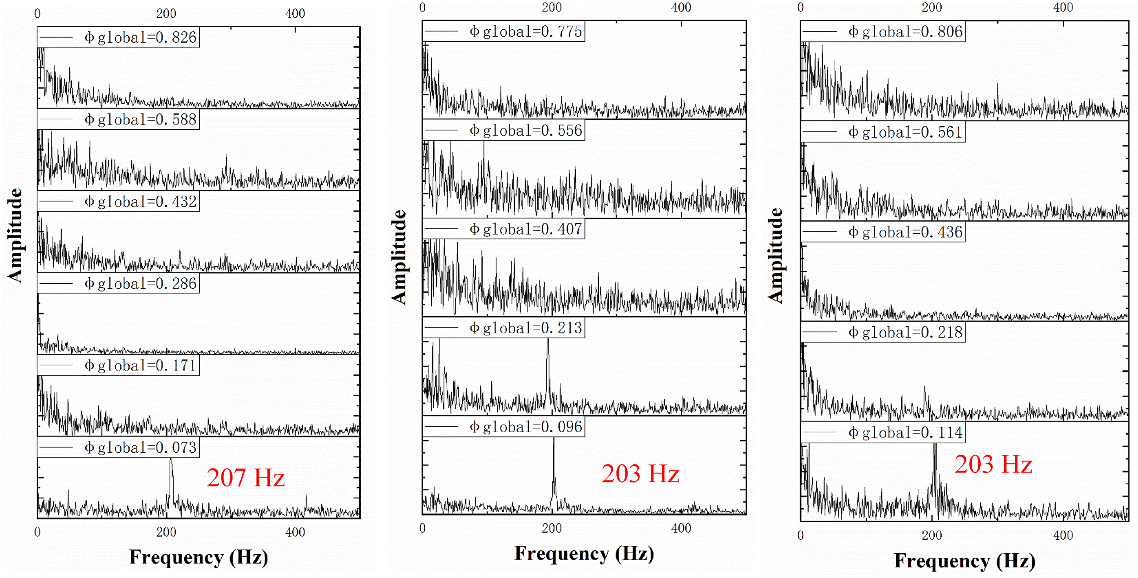
Based on the Fourier analysis results, in order to further understand the oscillation or pulsation characteristics of swirling flame, modal decomposition was performed to obtain the main temporal and spatial mode characteristics. Proper orthogonal decomposition (POD) and dynamic mode decomposition (DMD) have many successful applications in the analysis of fluid flow and combustion problems.2,36 The POD method sorts the modes according to the energy level, extracts the main spatial modes and the corresponding time coefficient through the reduced order reconstruction of the flow field. Sometimes, however, POD modes are the result of coupling of coherent structures with multiple frequencies. Although DMD method can obtain single-frequency spatial modes, it is sensitive to data noise. Moreover, DMD lacks a generally accepted method to sort eigenvalues, making it difficult to determine the primary modes. SPOD 37 has part of advantages of both POD and DMD. It can not only resolve the single-frequency coherent structure, but also is not difficult to determine primary mode. SPOD were used to decompose the experimental data, and comparative analysis was conducted.
The SPOD calculation method adapted here is developed by Aaron et al. 38 Hamming Windows with a length of 200 are used to block the data of each condition, and the last 100 sets of data for the Nth block are the same as the first 100 sets of data for the next block. SPOD analysis of OH-PLIF images in all working conditions shows that there are similarities with Fourier analysis results, but there are also differences. The similarity is that the disturbance of about 200 Hz is resolved in near-LBO with an airflow of 110 g/min, and all the conditions are close to flameout. The difference is that SPOD results has resolved the characteristic frequencies in all near-LBO conditions with airflows of 110 and 174 g/min. By comparing the energy spectra and the spatial modes, it is found that the results can be classified, and are consistent with the discussion of flame morphology classification in Section 3.1. “Morphology of swirling flame.” Among them, flames II and III only exist in near lean flameout of burner A1-B2 at an airflow rate of 174 g/min.
The first is about flame I. Figure 8 shows the SPOD results near-LBO when the airflow rate is 110 g/min. All the first two modes from 200 to 220 Hz in spectra have higher energy. The spatial modes consist of the symmetric disturbance and the asymmetric disturbance. The symmetric mode presents as global oscillation, while the asymmetric mode can be regarded as rotational perturbation in inner shear layer. Among them, the two modes of the burner A2-B1 appear to be asymmetric modes, but in fact the first mode represents the global oscillation, which can be inferred from the color scale of the spatial mode. That is, the negative depth of the color scale of this mode is much greater than the positive depth. In addition, all the spectra also have characteristics of low rank 39 at range of 410–425 Hz. The corresponding spatial modes are characterized by axial traveling waves, which mainly exist in the downstream where jet breaks down. 20
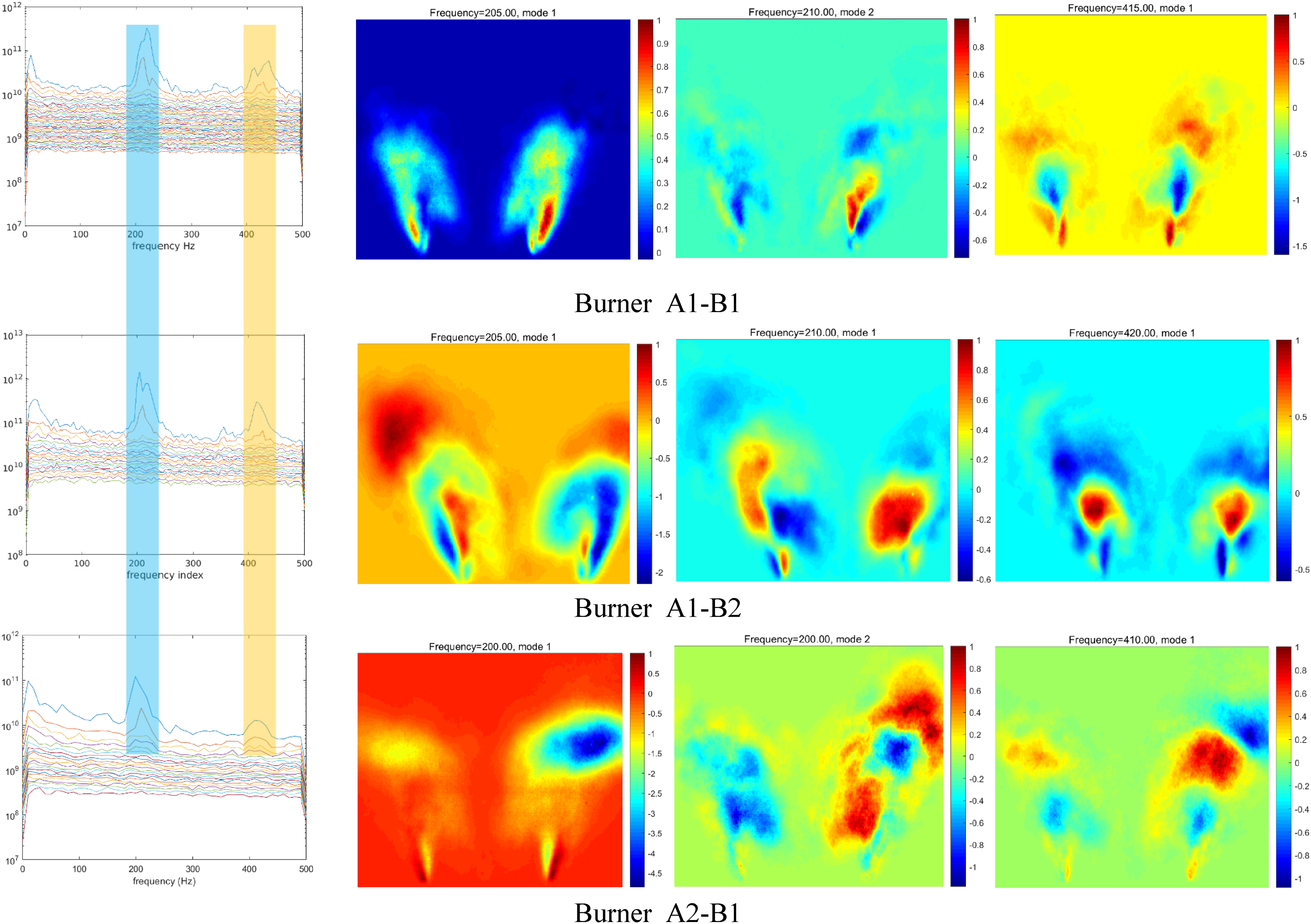
SPOD eigenvalue spectra and spatial mode of swirling flames near LBO, air 110 g/min, flame I.
Figure 9 also shows a low-rank behavior with a frequency of about 400 Hz at near-LBO when the airflow is 174 g/min for burner A1-B1 and A2-B1. Similar to the high frequency disturbance in Figure 8, the outer flame appears as a radial disturbance, while the downstream appears as a symmetrical longitudinal wave disturbance.
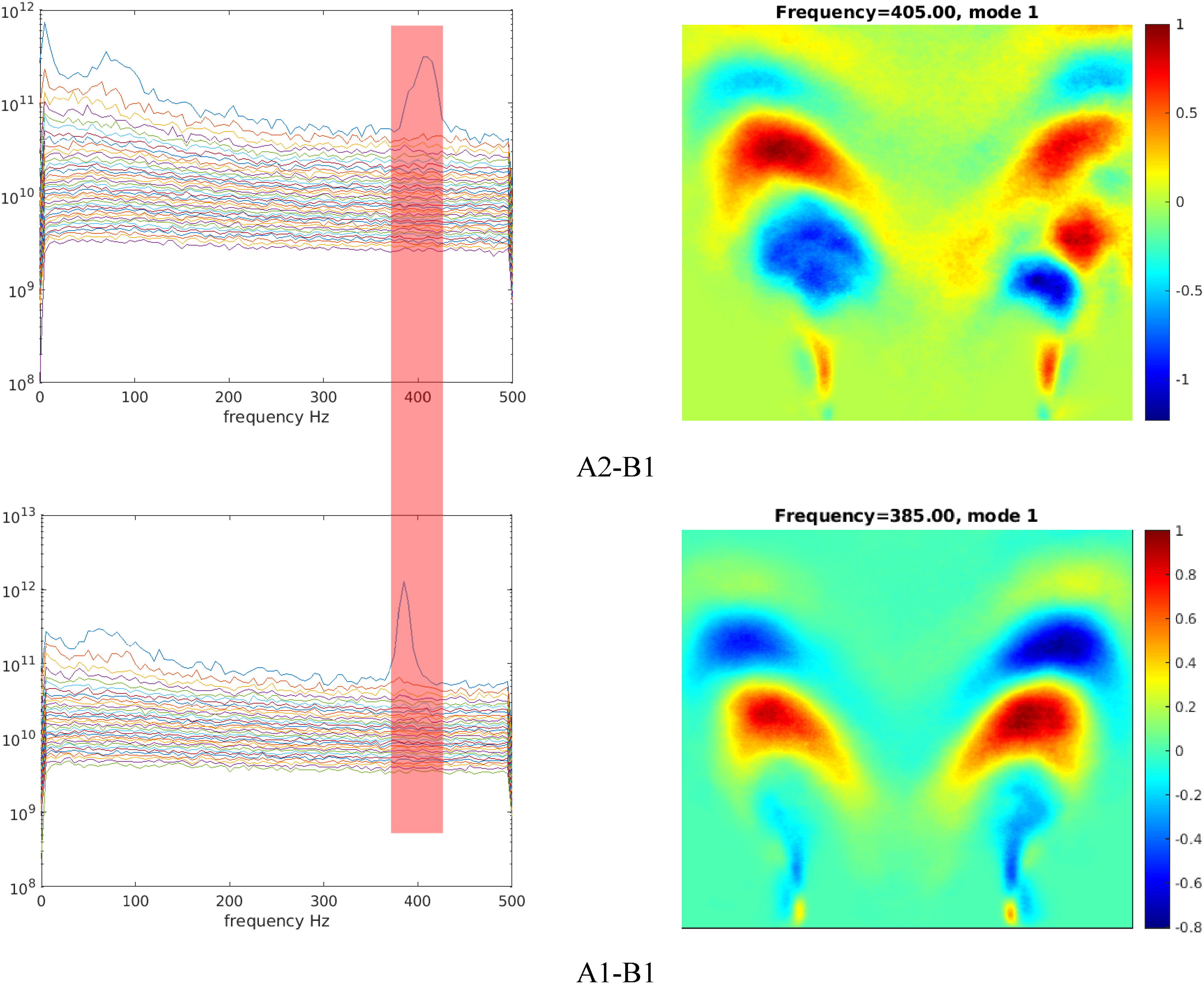
SPOD eigenvalue spectra and spatial mode of swirling flames near LBO, air 174 g/min, flame I.
These are the SPOD results of flame I. The high amplitude-frequency characteristic of about 200 Hz exists at 110 g/min airflow, independent of swirl conditions. The high-amplitude frequency characteristic of about 400 Hz exists in 110 and 174 g/min at the same time, and the spatial modes of each working condition are also presented as longitudinal waves.
The second is about flame II. When the burner A1-B2 is near flameout at 174 g/min, flame II and flame III appear alternately, as described in Section 3.1. “Morphology of swirling flame” and Figure 3. All PLIF results within 245–1000 ms were selected to analyze the modal characteristics of flame II. As shown in Figure 10, the eigenvalue spectrum shows two frequency ranges, namely 220 and 330–370 Hz, which is similar to the SPOD results of flame I at 110 g/min air. The difference is that the 220 Hz energy amplitude is much lower than the amplitude in the wide band of tens of Hertz. The 220 Hz spatial mode shows an oscillation characteristic. However, due to its low energy amplitude, this oscillation is not obvious in the Fourier analysis results. For the second frequency range 330–370 Hz, the spatial modes show the coupling of asymmetric modes and longitudinal modes, where the asymmetric modes correspond to the pulsation behavior of the flame in the inner shear layer.
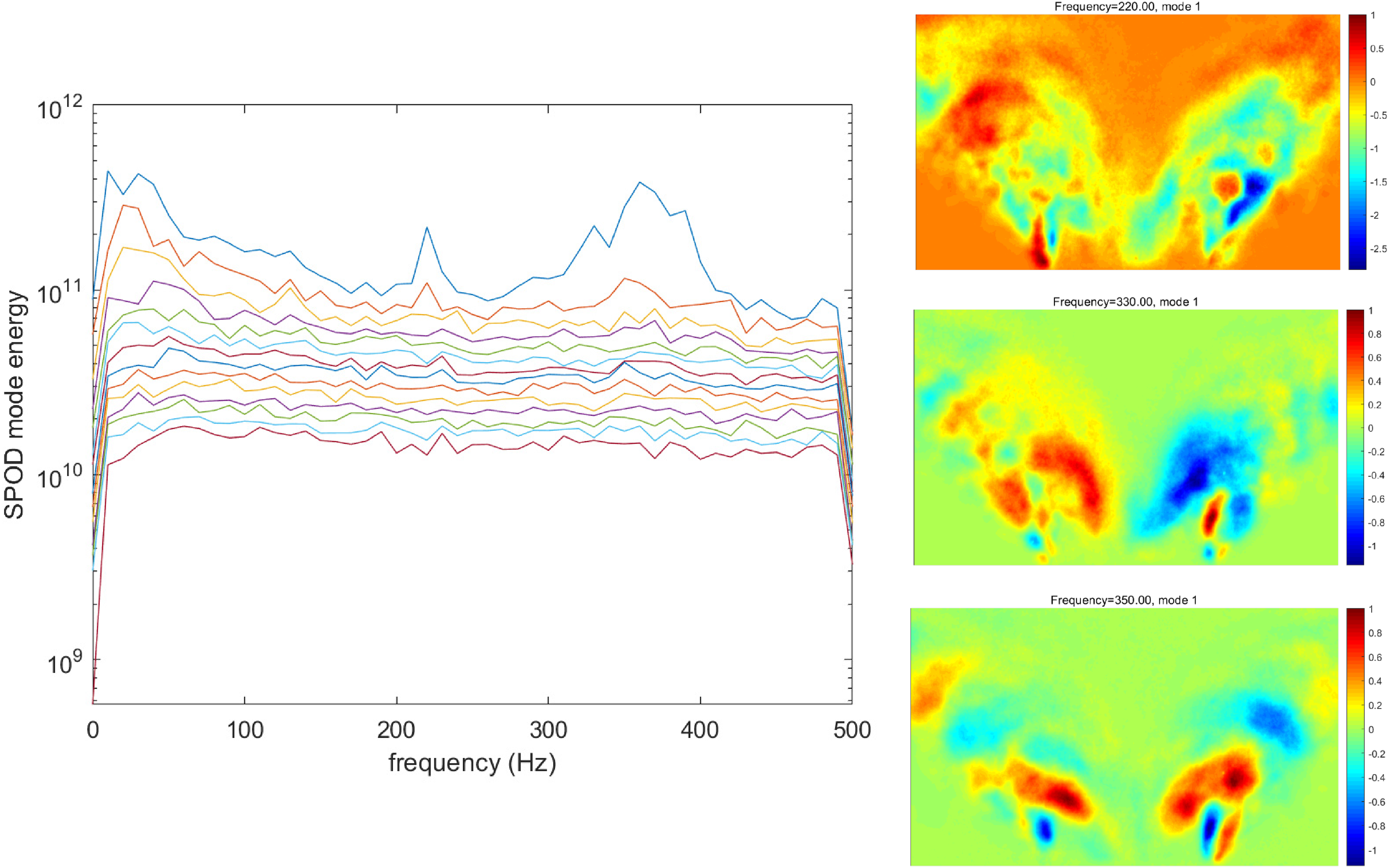
SPOD eigenvalue spectra and spatial modes of swirling flames near LBO, air 174 g/min, flame II, burner A1-B2.
Finally, flame III. For the near-LBO condition corresponding to Figure 3, continued reduction of methane flow results in a complete transformation of flame form to III and flameout. 440 PLIF images were taken within 440 ms. The corresponding SPOD results are shown in Figure 11. The eigenvalue spectrum has a significantly high energy only at about 320 Hz. Its spatial mode is asymmetrical disturbances which can be regarded as rotational modes and exist at the exit of the primary swirler nozzle.
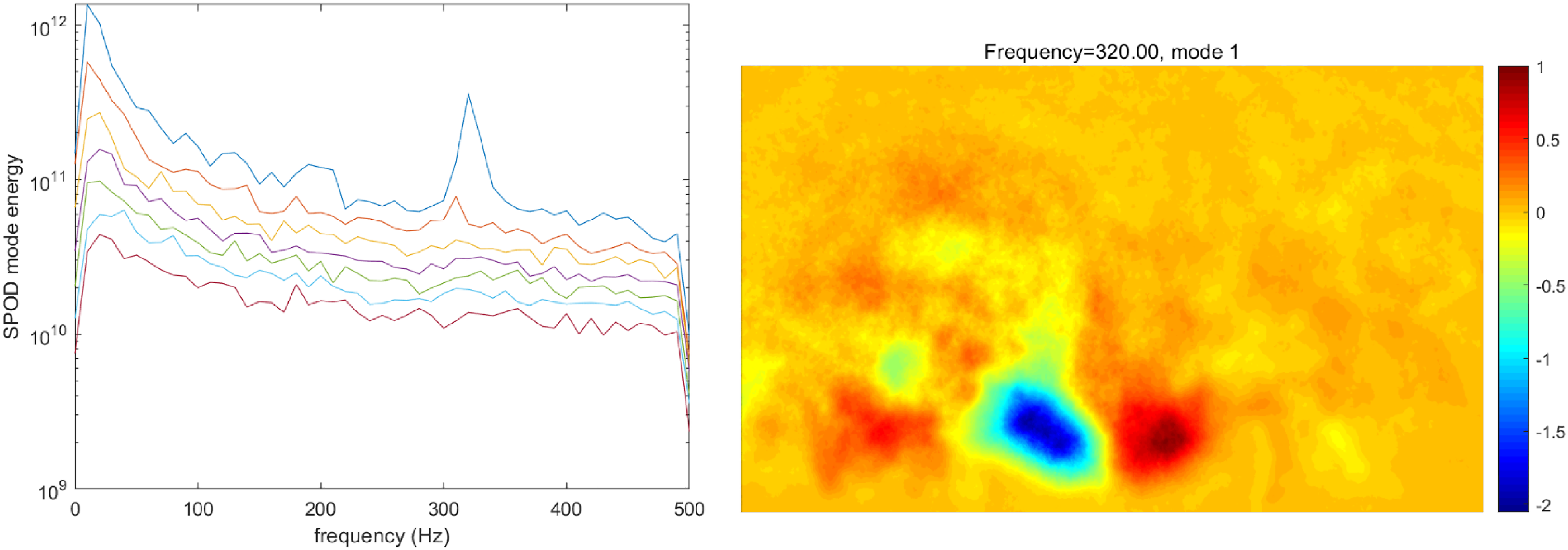
SPOD eigenvalue spectrum and spatial mode of swirling flame near LBO, air 174 g/min, flame III, burner A1-B2.
In this paper, the high-speed OH-PLIF technique was used to observe the characteristics of non-premixed swirling flame from stable to near-LBO. Burners can be divided into three types according to the combination of primary and secondary swirlers, namely A1-B1, A1-B2, and A2-B1. The abundant experimental results can be used to verify combustion model. Flame structures are also classified into three types and compared with results in some literature. A unique swirling flame structure with outer flame introduces a lean flameout mechanism that is greatly different from that of conventional swirling flame which may provide a novel idea for the LBO limit broaden. The dynamic characteristics are resolved by SPOD. Main conclusions are as follows:
Flames can be divided into three classes: flames I, II, and III. Both flames I and II have dual structure, which are inner flame and outer flame, respectively. The outer flame exists in the outer shear layer and is attached to the inner wall of the air annular nozzle and only moves or deforms within a small space. Different from the central bluff body swirl flame,7,14 the outer flame in this study is more likely to be caused by flow separation in the inner wall of the annular nozzle. What is more, the outer flame is more stable when the primary swirler is weakened, but it is more likely to disappear when the secondary swirler is weakened. The inner flame of flame I is M-shaped and remains connected or occasionally disconnected from the outer flame. While the inner flame of flame II is V-shaped and remains disconnected from the outer flame. As for flame III, there is no outer flame in its flame structure, and the corresponding inner flame is also different from the previous two, which is manifested as radially propagating outward into ORZ and even propagating to the top wall. In the presence of outer flame, the lean flameout mechanism of swirling flame is quite different from that of the conventional. Flameout of flames I and II always begins with the appearance of local extinguishing at the root of the outer flame, while the inner flame has already been unable to be stationary at this time. The flameout mechanism of flame III is consistent with the conclusions in 4, which starts from the unstable behavior of the flame root upstream of the IRZ, that is, the repeated extinguishing and reignition process. Under the same airflow condition, the flame III without outer flame has a higher flameout equivalent ratio than the other. In the future, on the premise of ensuring the consistency of the inner flame, the effect of the outer flame against lean flameout can be quantitatively analyzed by comparing the LBO characteristics when the external flame exists/disappears. The experiment captured that the three kinds of flame all have complex unstable behavior under near-LBO conditions with airflow of 110 and 174 g/min, which mainly includes global flame oscillation, asymmetric disturbance and longitudinal disturbance propagating along the axis. Different flame forms have different dynamic characteristics. The common point is that the asymmetric disturbance of each flame mainly exists in the inner shear layer, and the longitudinal disturbance mainly exists in the jet breaking down region downstream of the shear layer. Flame oscillation mainly exists in near-LBO condition with an airflow rate of 110 g/min. The flame is in the form of I, and the oscillation frequency in each burner is about 200 Hz. Flame I has characteristic modes in two frequency range, among which the spatial mode of about 200 Hz at 110 g/min airflow includes not only flame oscillation, but also asymmetric flame disturbance in the inner shear layer. In addition, a characteristic disturbance of about 400 Hz exists in both airflow conditions. The spatial mode indicates that the 400 Hz disturbance propagates in the form of a longitudinal wave. Under the near-LBO condition of 174 g/min airflow, although flame II also has two characteristic modes in the frequency range, it mainly presents asymmetric disturbance and longitudinal wave disturbance in the range of 330–370 Hz. As for flame III, it is observed in the flameout process of 174 g/min airflow that the SPOD characteristic value spectrum has a characteristic frequency of 320 Hz, which is manifested as an asymmetric disturbance at the outlet of the central air nozzle.