
Abstract
Achieving full premixing and complete evaporation in lean prevaporized premixed combustors is challenging as it depends on the spray injector characteristics, prevaporisation strategy, and flow conditions. This article experimentally explores the stability and structure of a turbulent swirling n-heptane spray flame under various degrees of prevaporization. The results show that preheating the air to 343 K and 393 K has little effect on the lean blow-off velocity, while recessing the fuel injection significantly decreases the lean stability limit. To correlate these limits, various attempts to define a Damköhler number were made, but unlike previous studies with no prevaporisation, the difficulty in defining laminar flame speed in the present case does not allow a single correlation to work for all degrees of prevaporization. Four stable cases that differ in equivalence ratio, air preheat temperature, and fuel injection recess are investigated using one-dimensional PDA, OH* chemiluminescence and CH
Introduction
The combustion of liquid fuels is often more complex than that of gaseous fuels because of the presence of droplets in the mixture of air and fuel vapour. When a single liquid droplet burns in air, the flame is a non-premixed flame that burns at stoichiometry in the gaseous phase surrounding the droplet.
1
Non-premixed flames, however, are often undesirable because of their high NO
While many lab-scale LPP experiments can achieve full prevaporization and premixing, these phenomena are often not achieved in practice even in gas turbines that claim to use LPP.
4
One reason behind this difficulty is that full prevaporization and full premixing have opposite requirement in gas turbine combustion – the former requires the droplets to be near a heat source (i.e. the flame) while the latter needs the initial spray to be sufficiently far from the flame.
5
As a result, many LPP combustors may actually be burning with a spray flame at various degrees of prevaporization. In these flames, some fuel will have enough time to evaporate and mix with air, which may result in a local equivalence ratio within the nominal flammability limits. Meanwhile, the remaining fuel droplets will produce a non-premixed flame. In addition to these two combustion modes, the presence of droplets has been shown to affect many flame characteristics, such as the flame speed and its propagation mechanism6,7, ignitability
8
, NO
Given the effect of droplets on the critical characteristics of the flame and the two different combustion modes, it is not surprising that the presence of droplets can affect flame stability. In premixed flames, LBO is determined by the competition between chemical kinetics and fluid mechanics time scales, which can be described by the Damköhler number. 11 For a spray flame, these factors contribute to LBO as well, but it is further complicated by the effect of droplets. In one of the earlier studies, Mizutani and Nakajima 12 found that adding kerosene droplets to a propane–air mixture while keeping the overall equivalence ratio fixed extended the lean stability limit and increased the burning velocity. Others have tried to understand the parameters governing the LBO limit using different properties of the fuel, such as volatility, but the results are less conclusive. Grohmann et al. 13 tested the LBO limit of a dual-swirl burner for four different liquid fuels and found that larger fuel droplet and slow-vaporizing fuels are associated with wider lean stability limit. In contrast, at similar air inlet temperatures, both Burger and Yates 14 and Rock et al. 15 found that fuels which vaporize easily were the most resistant to lean blow-off.
Studies have also examined LBO of spray flames with various the degree of prevaporization. Both Grohmann et al. 13 and Rock et al. 15 found that preheating the air improved lean stability limit. The Sydney Piloted Needle Spray Burner can increase prevaporization by recessing the fuel injection upstream of the burner exit, which also was found to increase blow-off velocity.16,17 This finding differs from when gaseous fuel was injected through the central pipe, which had an optimal recess distance that significantly extended the stability limit by increasing the inhomogeneity in the mixing of fuel and air. 18 Another study on the Sydney burner found that as the jet velocity increased and the acetone flame approached blow-off, the flame appeared to transition from a more non-premixed flame to a more premixed flame. 19 These studies suggest that air preheat, atomization recess, and air velocity are important parameters for prevaporization and the LBO limit.
The objective of this article is to examine the stability and structure of turbulent swirl-stabilized n-heptane spray flames with different amount of prevaporization, achieved by controlling the air preheat temperature and the recessing the fuel injection upstream of the burner exit. The lean stability limits at various air inlet temperature and fuel recess will be assessed. Then, four stable cases that differ in global equivalence ratio, air preheat temperature, and fuel recess distance respectively will be selected for further studies using direct photographs, 1D-PDA, OH* chemiluminescence, and CH
Methods
Experimental conditions
Diagrams of the burner used for the experiments are shown in Figure 1. The fuel was supplied from a pressurised tank kept at 5 bar using nitrogen gas. The fuel flow rate was controlled by a needle valve and was calibrated by weighing the mass of the fuel sprayed for 5 min using a stop watch with accuracy of 0.01 s and a scale with accuracy of 0.001 g. The fuel passed through a 7-micron in-line particulate filter and was then injected into the centre of the burner using an hollow-cone atomizer from the Lee Company (IAZA1200147K, cone angle of 50
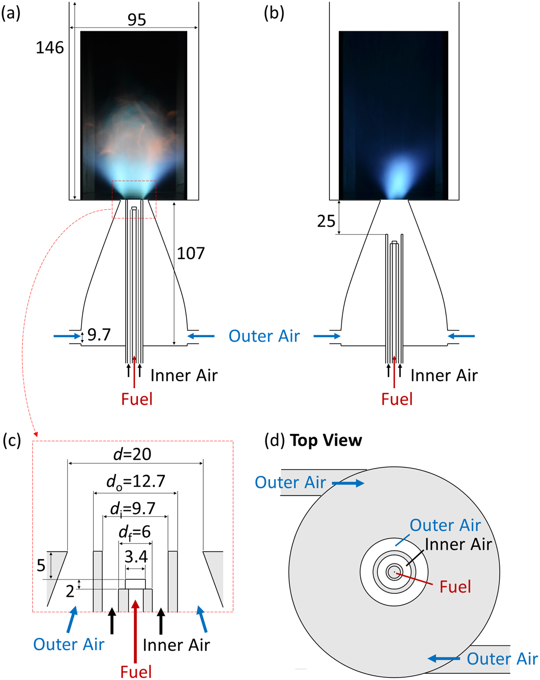
Diagrams of the burner with dimensions in millimetre (mm). The recess of the fuel and inner air (i.e. length of the premixer) can be adjusted by changing the height of the tubes in the centre. Two locations of fuel and inner air injections are used in this work: no recess (a) and 25 mm recess (b). A close-up of the cross section of the burner exit is shown in (c), and a top view of the premixer and burner exit is shown in (d).
The burner provides two separate streams for air injection. The two streams originated from a central compressed-air system with particulate and coalescent filters. The central air was then split into two streams at a T-junction. Each stream of air had its own mass flow controller, in-line heaters, and PID temperature controllers to set the flow rate and temperature. The temperatures of the two air streams were the same for all cases in this study. The inner air was injected in the axial direction without swirl. In contrast, the outer air was injected tangentially at the base of a cone-shaped premixer, which provided the swirl needed to stabilize the flame.
The relative positions of the fuel injector, inner air nozzle, and outer air annulus can be easily adjusted, which allows the degree of prevaporization to be varied. In this article, two configurations were used. Figure 1(a) shows the first configuration where the inner nozzle is flush with the exit plane, and the tip of the atomizer is 5 mm upstream of the burner exit. In the second configuration, the fuel nozzle and inner air nozzle were moved upstream of the burner exit by 25 mm, as shown in Figure 1(b). The atomizer is still 5 mm upstream of the inner air nozzle exit. This method of recessing the fuel will have some effects on the airflow since the inner and outer air can now begin to mix more upstream. This problem could have been avoided if only the atomizer was recessed while the inner air pipe exit stayed flush with the burner exit, but doing so resulted in large amounts of fuel hitting and accumulating on the inner wall of the inner air pipe during test runs, which was not desirable. Therefore in this work, recessing the spray involved moving both the fuel and inner air nozzles upstream. In all cases, the burner was enclosed by four quartz plates with the dimension of 150 mm
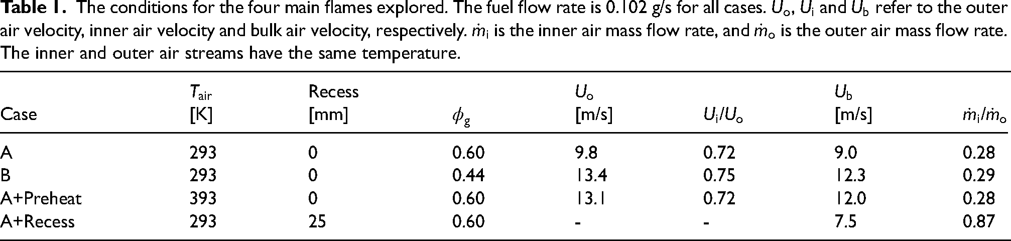
Four stable flames were selected for detailed measurements, and their conditions are listed in Table 1. The fuel flow rate was 0.102 g/s for all cases. Case A is the base case that has no preheating and no recess (the burner geometry shown in Figure 1(a)). Case B also has no preheating or recess, but it has higher air velocity and lower global equivalence ratio,
The conditions for the four main flames explored. The fuel flow rate is 0.102 g/s for all cases.
Experimental procedure and diagnostics
Droplet size and axial velocity were measured using a 1D LDA and PDA system from DANTEC. The transmitting probe consisted of two 514 nm laser beams. One of the two beams has been phase shifted by 40.00 MHz in a Bragg cell to allow measurement of negative velocity. The beams intersect in the vertical direction (axial) to create a measurement volume in the burner. The collection probe was placed at 70
High-speed OH* chemiluminescence images were taken at 5 kHz by a Photron SA1.1 monochrome high speed CMOS camera with 1024
The low-speed CH
Simulation of droplet evaporation
The evaporation of a heptane droplet is simulated to compare with the experimental data and to better understand prevaporisation. Details about the numerical method can be found in previous work.23,20 The code simulates a stationary heptane droplet in stationary air at 1 bar without considering any chemical reactions. The initial temperature of the fuel droplet is 293 K for all cases, and the initial temperature of the air is either 293 K or 393 K. Since the simulations are not the main focus of this paper, the results are presented in Supplemental Materials and are only briefly discussed in the main body of this article.
Results and discussion
Lean stability limit
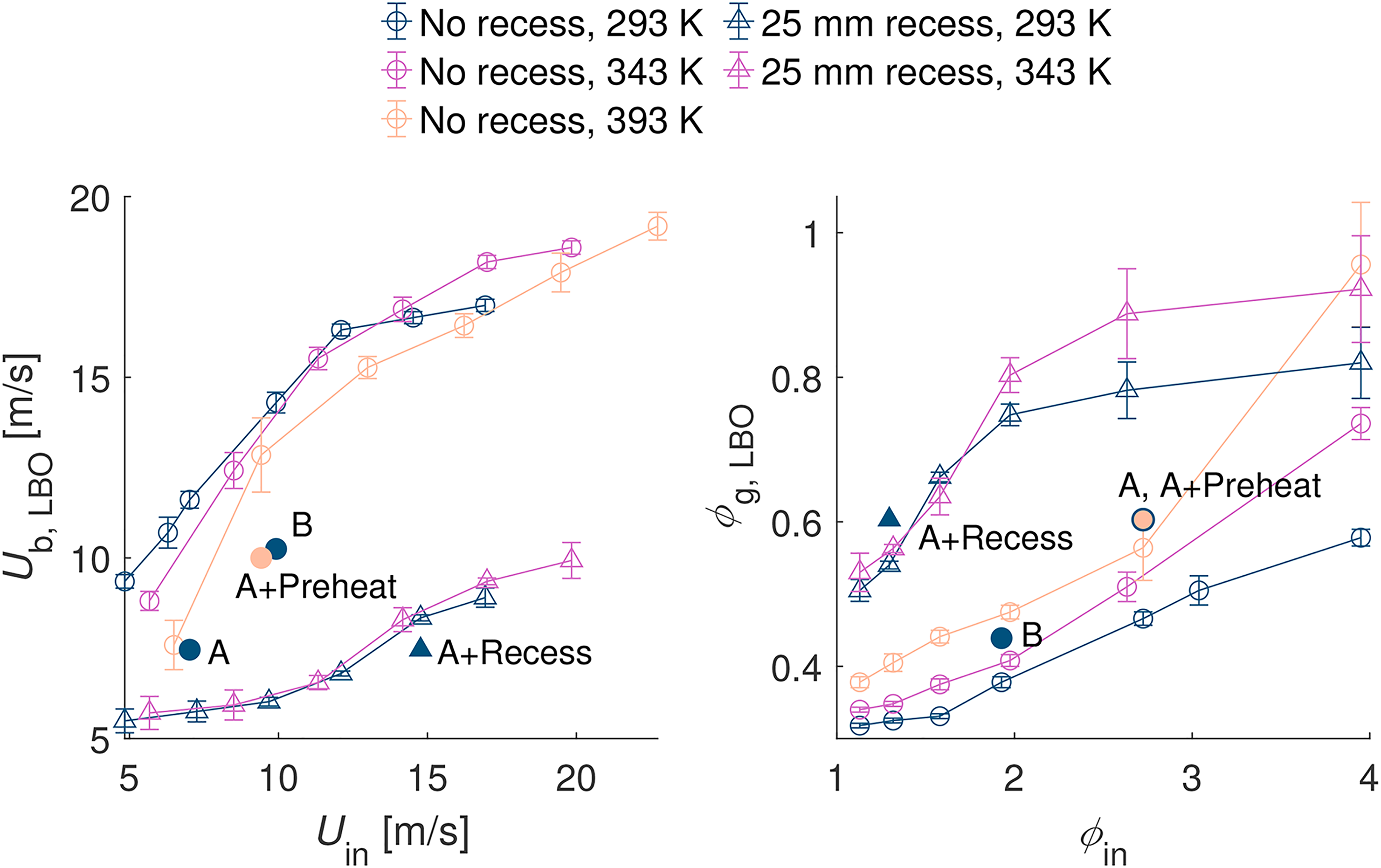
The stability limits of the burner with and without fuel injection recess and at air preheat temperatures of 293 K, 343 K and 393 K are presented in Figure 2 for a range of inner air flow rates. For each combination of recess and air preheat temperature, the blow-off condition was found by first igniting the flame at flow rates far from blow-off. Then, with the fuel flow rate fixed at 0.102 g/s and inner air flow rate fixed at a specific value, the outer air velocity was increased in increments of approximately 0.3 m/s every 20–30 s until the flame extinguished. The procedure was repeated for at least three times for each condition. The maximum standard deviation of the blow-off velocity is 8%, though it is below 3% on average.
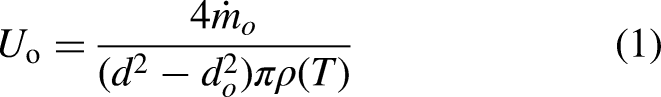
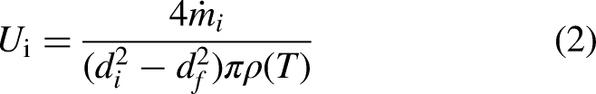
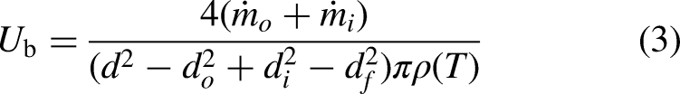
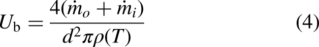
The blow-off bulk velocity,
The effects of the flow and mixture conditions on the LBO of the flame are shown in Figure 2. The left subplot shows the bulk velocity at LBO,
Increasing the air preheat temperature led to higher
To further understand the blow-off limit and compare it with existing studies in the literature, we can try to correlate these limits with global correlations. It is also vital to explore these correlations for LBO because this is what engineers would attempt to do when trying to design a new burner based on LPP ideas. Therefore, it is useful to see not only how it works, but also how one might estimate the parameters going into it. One such correlation is the one first proposed by Radhakrishnan et al.
25
and originally used for turbulent bluff body premixed flames, but also applied for in studies with heptane spray flames.26,27 By definition, blow-off is expected to occur when the inverse of the Damköhler number (Da) of the flow exceeds a critical value, 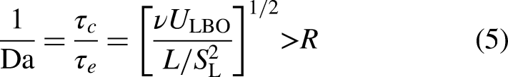
In first method of calculating the flame speed, the mixture is evaluated at stoichiometry; this approach was taken in previous studies with spray flames.26,27 The critical value of 1/Da as a function of
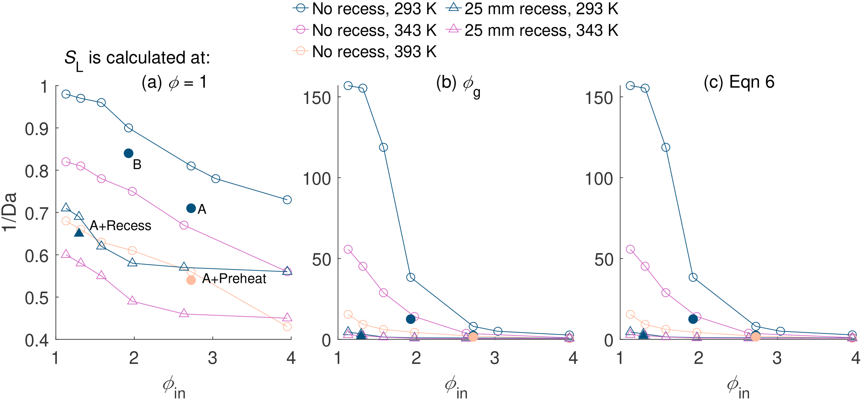
The critical 1/Da for the blow-off correlation first proposed by Radhakrishnan et al.
25
The flame speed used to calculate 1/Da is evaluated at stoichiometry (a), at the global equivalence ratio
At the limit of full prevaporization and premixing, it would be incorrect to take the stoichiometric condition to evaluate the flame speed. Instead,
Finally, a third method of calculating 
The attempts in this section show that the LBO limit of spray flames with prevaporization could not be easily predicted with global correlations. The complexity of prevaporization and presence of a polydisperse spray makes it especially difficult to evaluate flame speed. Furthermore, these results indicate that local droplet-induced effects – thus far not accounted for in LBO-prediction correlations – must also contribute significantly to flame extinction and must be accounted for in future works.
Direct flame photos
To better understand the effect of prevaporization, four stable flames that differ in global equivalence ratio, air preheat temperature, and fuel injection recess distance respectively are investigated in more detail in the remaining of this paper. The four flame conditions are summarized in Table 1, while their photographs in the visible spectrum are shown in Figure 4. Imaged in the visible spectrum or to the naked eye, lean premixed hydrocarbon flames are characterised by a typical blue hue while soot has a distinct orange colour. As a first indication of the characteristics of each of the flames investigated in detail here, one can infer their degree of prevaporization and premixing based on direct photographs. Case A, being the base case of this study, has no air preheat or fuel injection recess. Even though it has a lean global equivalence ratio of 0.6, it is still marked by significant amount of soot, which is formed at around 1
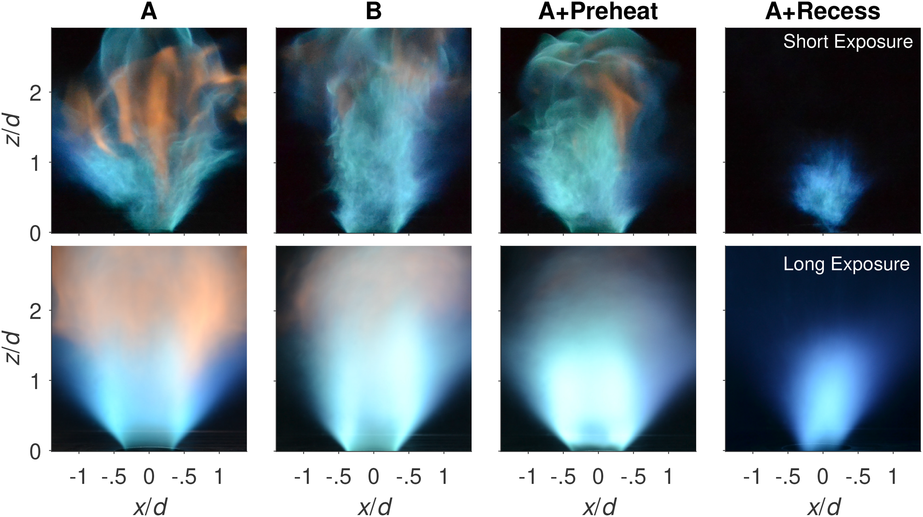
Direct photos of four stable cases. The top photos are taken at short exposure (shutter speed of 4 ms, f/5.6). The bottom photos are taken at long exposure (shutter speed of 769 ms, f/5.6).
These photos can be compared against that of other confined, turbulent, swirling, spray flames. DLR has a confined, swirl-stabilized burner with a pre-filming airblast atomizer. 13 Their reference flames look less sooty, wider, and shorter than the more non-premixed cases presented in this paper. The flames also seem to be unattached, like Case A+Recess. Their flames do not have droplets near the central axis, whereas the burner in this article does, which will be shown in the next section on droplet velocity and size. This difference in fuel distribution may have contributed to the different flame appearance. The Cambridge swirl flame burner is another confined spray burner.26,27 In addition to using swirl to stabilize, these flames are also stabilized by a bluffbody in the centre of the burner exit. The atomizer is placed in the centre of the bluffbody, while the air flows around the outside of the bluffbody. As a result, these flames have an inner cone that aligns with the spray cone, and an outer cone along the shear layer and is attached to the corner of the bluff-body. This double cone structure is not observed in the flames in the current work. Their bluffbody likely also acts as a physical barrier between the fuel and air stream, limiting the mixing between the two streams. This might have caused the flames to appear sooty like the less-premixed cases in this article.
Droplet velocity and size
Results and analysis from the PDA measurements are presented in this subsection to understand droplet size and velocity in the four stable cases. Figure 5 presents the normalized average velocity, RMS of the normalized fluctuating velocity and the SMD (
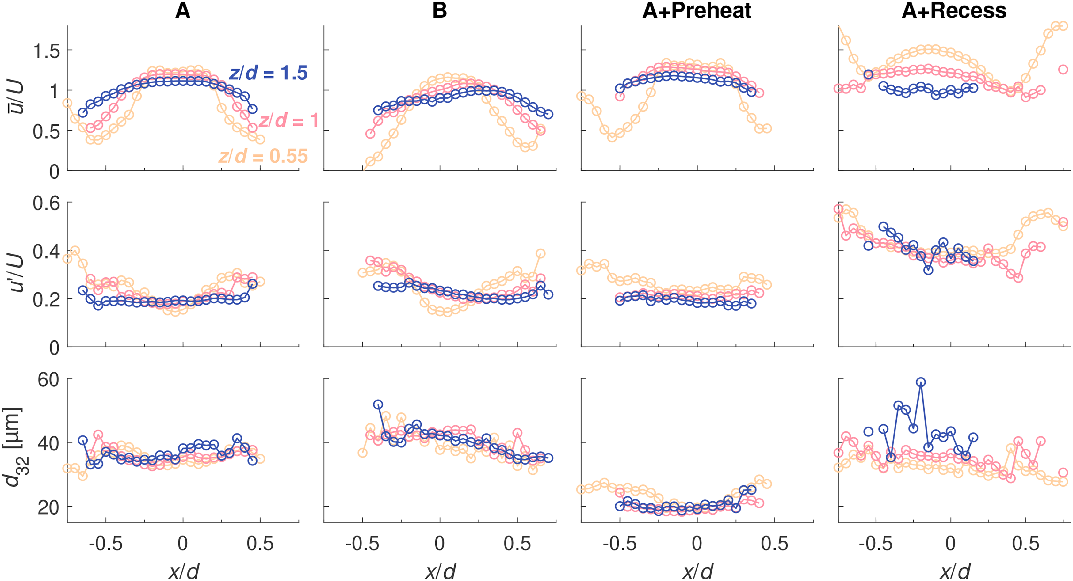
The distribution of normalized average velocity, normalized RMS of the fluctuating velocity and SMD of droplets at
Case A has the highest average velocity near the central axis at all three heights, which is likely because the droplets here are being carried by the inner air jet. As one moves away from the central axis, the velocity decreases and reaches a minimum at around
Case B has higher air velocities than Case A does, which decrease the residence of the droplets and should result in less prevaporization. Given that the normalized droplet velocity and size profiles are similar to those observed for Case A, however, this effect on prevaporization should be small.
The air preheat temperature is increased by 100 K in Case A+Preheat. Preheating the air increases the bulk air velocity that in turn increases the droplet velocity, as evident from the comparison of droplet velocity PDFs in the left column of Figure 6. The higher air velocity reduces the residence time for the droplet, which alone should decrease prevaporization, but the higher air temperature also speeds up droplet evaporation. The net result is an increase in prevaporisation. This is apparent from its significantly smaller SMD at all locations. The PDFs of droplet diameter also peaks at a smaller diameter than the case without preheat, which indicates that preheating the air results in a higher fraction of small droplets.
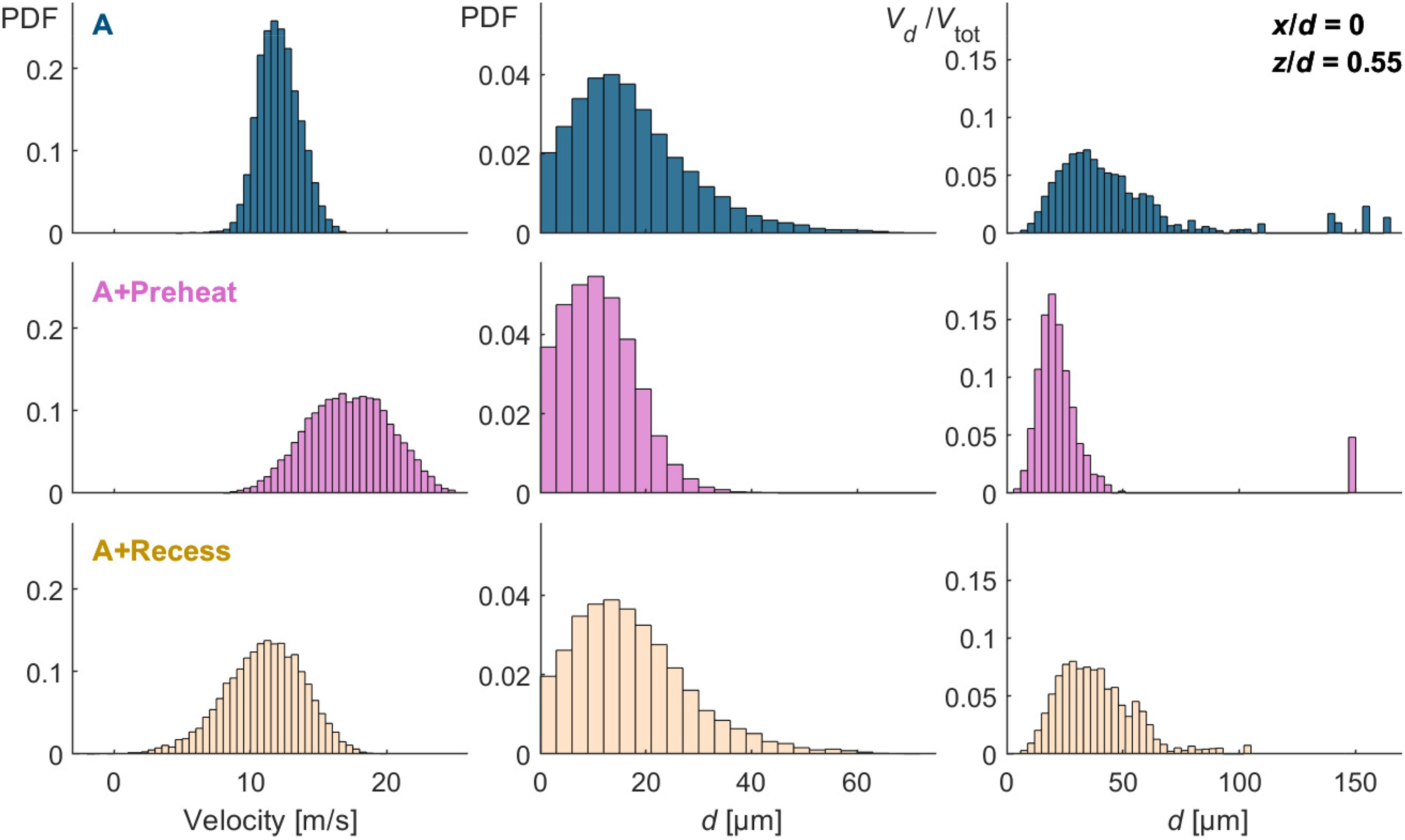
The probability density function (PDF) of droplet velocity (left) and diameter (centre) as well as the liquid volume contained in droplets of a particular diameter,
Recessing the atomization in Case A+Recess increases the droplet residence time and allows more fuel to evaporate before reaching the flame. Droplets formed from pressure atomizers usually have high initial velocity. When the atomizer is recessed, the droplets will have slowed down more by the time they reach the burner exit. This lower droplet velocity also contributes to a higher residence time and more prevapoization. Although its SMD values in Figure 5 at most locations are similar to those in Case A, the enhanced prevaporization is still evident: at
The effect of fuel recess is also evident from the right column of Figure 6, which shows the liquid volume contained in droplets of different diameter (
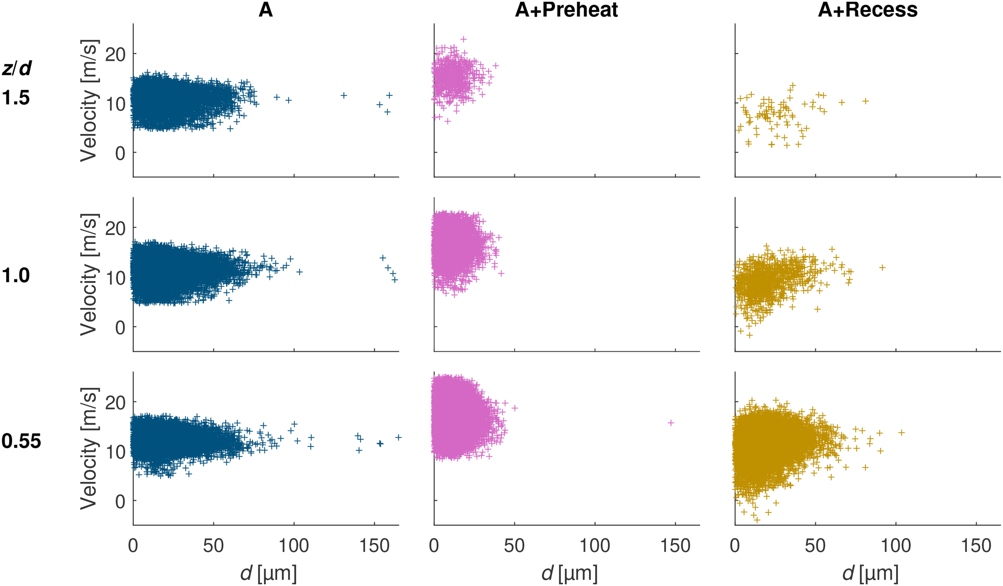
The velocity and diameter of every droplet in the sample at
The droplet size measurements agree with the results from the simulation of droplet evaporation at conditions of Cases A, A+Preheat and A+Recess, which are presented in Supplementary Materials. The droplets simulated at Case A conditions have the largest diameters and supports the hypothesis that Case A is the closest to a non-premixed flame. The droplets at the conditions of Case A+Preheat have significantly lower SMD values than Cases A and A+Recess, which is also found in the PDA measurements. Recessing the fuel injection decreases droplet size in a different way: by giving the evaporation a head start and increasing the droplet residence time. These factors slightly decreases the droplet diameter, but they are not as effective preheating the air. This finding is consistent with the experimental observation that Cases A and A+Recess have similar SMD values.
HR location
OH* chemiluminescence is used qualitatively to identify the HR locations and flame shapes. The average OH* chemiluminescence after applying inverse Abel transform are presented in Figure 8. The HR zone for Case A is a hollow cone that corresponds to the shear layers and sits in the outer air annulus. Its shape resembles that of other swirling spray flames on burners of similar geometry. 34
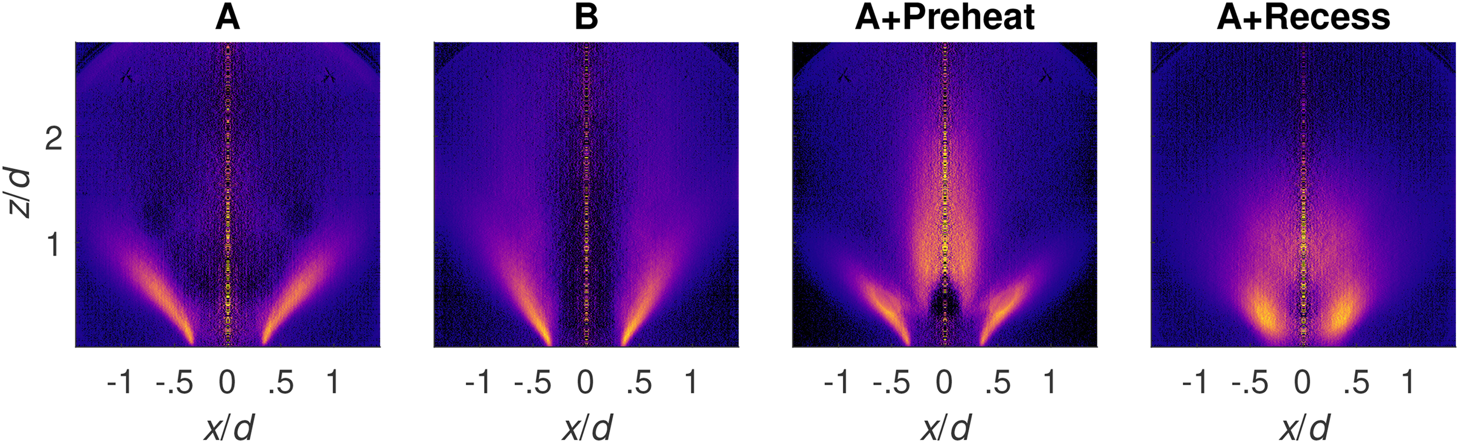
Mean images of OH* chemiluminescence after inverse Abel transform for the four stable cases.
When the air velocity is increased in Case B, the HR zone remained cone-shaped but the cone is narrower than in Case A. The narrow cone corresponds to the narrower flame photographed in Figure 4 and is presumably caused by the higher air velocities. Case B also has less OH* signal around the central axis than Case A has because the higher flow inner air flow rates leads to lower residence time and less chemical reactions occurring around the central axis.
Increasing prevaporization altered the HR zones significantly. Case A+Preheat still has a conical HR zone near the shear layers but it has a second HR region that resembles the shape of an elongated Bunsen flame on the central axis. The OH* signals from the two HR zones are similar in strength. Given that this case has smaller droplets, one possible explanation for the inner HR zone is that this case has enough prevaporization and premixing between the fuel vapour and the inner air stream to achieve significant HR downstream of the inner air exit. On the other hand, the remaining droplets still burn near the shear layer as they do in Cases A and B, and thus the outer conical HR zone is still observed. It’s worth noting that dual reaction zones have been observed before using OH-PLIF for ethanol spray flames on two versions of the Sydney piloted spray burner.19,17 They saw an inner reaction zone due to the premixing between fuel vapour and carrier air, and an outer reaction zone due to the pilot heat, which has some similarity with the dual HR zones of Case A+Preheat.
The HR zone for Case A+Recess is different from the other three cases. The conical HR zone near the shear layer is not observed; instead, the flame has a circular-shaped HR zone significantly thicker than other cases just downstream of the burner exit. The large difference observed between this case and the cases without recess could be due to spray momentum. The droplets in Case A+Recess have the lowest velocities and thus get trapped by the swirl more easily, which results in a thicker HR zone downstream of the burner exit. Additionally, recessing the fuel injection promotes premixing and prevaporisation by increasing the droplet residence time. As a result, OH* signal is observed near the central axis downstream of the inner air exit, like in Case A+Preheat.
CH
O-PLIF
CH
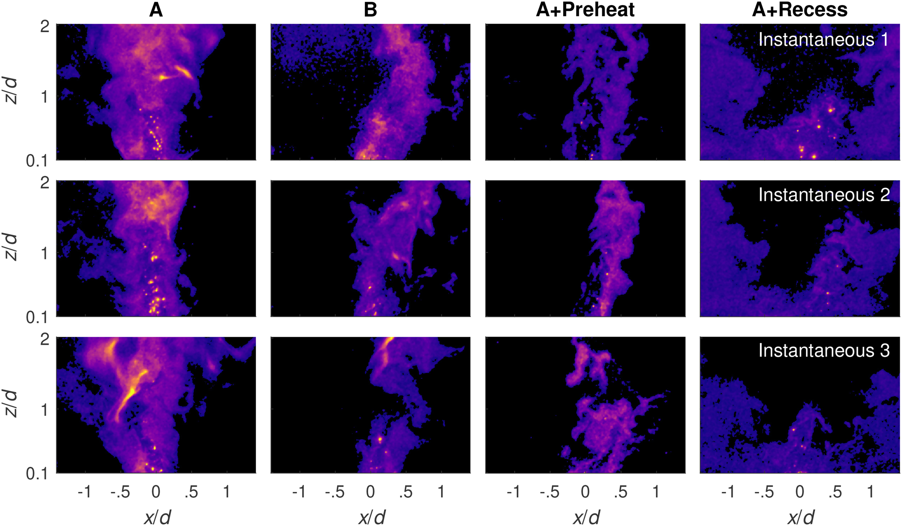
Instantaneous images of CH
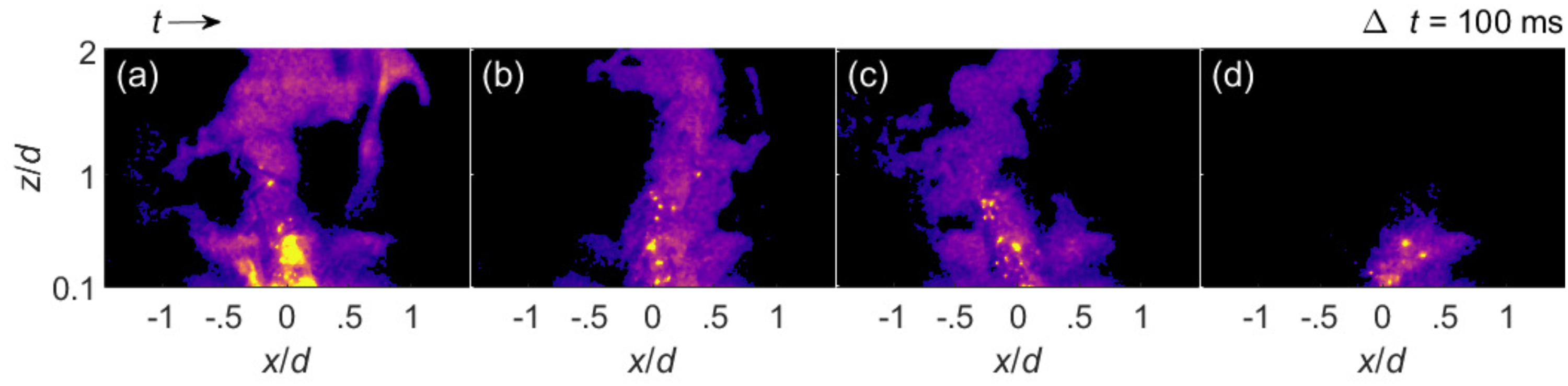
Sequence of CH
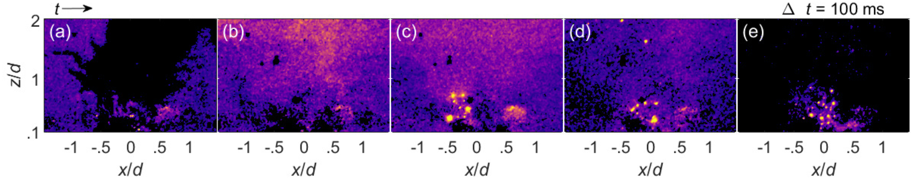
Sequence of CH
CH
Case B also has the strongest CH
Case A+Recess has a different CH
Given that recessing the fuel had large effect on the LBO limit, we can compare the CH
Even though the images contain interference, it is clear that the change in CH
Conclusions
This study investigated the stability and structure of turbulent swirling n-heptane flames with different degrees of prevaporization, which was varied by changing the air preheat temperature and the recess distance of the fuel injection. Recessing atomization by 25 mm and decreasing the inner air velocity both reduced the blow-off velocity. In contrast, preheating the air to 343 K or 393 K had little to no effect on the LBO limit. A correlation based on the Da number was applied to the data, but it was not able to accurately predict the blow-off limit. The results also did not agree with the trends from previous studies that used the same correlation. These findings suggest that the lean stability limit of spray flames subjected to prevaporization cannot be predicted using such simple correlations.
To understand how different variables affect the behaviour of the flame, four stable flames that differed in global equivalence ratio, air preheat temperature and fuel injection recess distance were studied in more detail using diagnostics. The PDA results showed that preheating the air decreased the SMD by shifting the droplet diameter PDF to the smaller side. Although the SMD values remained similar when fuel injection was recessed, fewer droplets with extremely large diameters were still found in the sample. Despite their reduced number, those are expected to heavily impact the flame front locally due to their size and significant amount of fuel released, which may partly explain the results concerning the Da-based correlation for LBO prediction.
All cases without recessed atomization had conical HR zones near the shear layers as revealed by OH* chemiluminescence. When the air was preheated to 393 K, an additional HR zone downstream of the fuel injection was enabled by the increased prevaporization and premixing between the fuel vapour and the inner air stream. Also, due to increased prevaporization, an HR zone further downstream of fuel injection was observed with recessed fuel injector. Additionally, the droplets in the recessed case had less momentum by the time they reached the burner exit, thus getting trapped by the swirl more easily and, in turn, resulting in another thick HR zone close to the burner exit. Regardless of the air preheat temperature, strong CH
These experiments show that different methods of prevaporisation, which differ by small differences in droplet profiles, significantly affect the flame structures and their blow-off mechanisms. Ultimately these parameters affect the stability limit of the burner and contribute to the difficulty in predicting the blow-off conditions of prevaporised flames. The data are useful for validating turbulent combustion theories as they focus on challenging-to-model phenomena and will be available in the Cambridge Swirl Flame Database. 43
Supplemental Material
sj-zip-1-scd-10.1177_17568277231159173 - Supplemental material for Stability and structure of lean swirling spray flames with various degrees of prevaporization
Supplemental material, sj-zip-1-scd-10.1177_17568277231159173 for Stability and structure of lean swirling spray flames with various degrees of prevaporization by Jiayi Wang, Pedro M. de Oliveira, Rohit Singh Pathania, Ingrid El Helou and Epaminondas Mastorakos in International Journal of Spray and Combustion Dynamics
Supplemental Material
sj-sj-pdf-2-scd-10.1177_17568277231159173 - Supplemental material for Stability and structure of lean swirling spray flames with various degrees of prevaporization
Supplemental material, sj-sj-pdf-2-scd-10.1177_17568277231159173 for Stability and structure of lean swirling spray flames with various degrees of prevaporization by Jiayi Wang, Pedro M. de Oliveira, Rohit Singh Pathania, Ingrid El Helou and Epaminondas Mastorakos in International Journal of Spray and Combustion Dynamics
Footnotes
Acknowledgements
The authors kindly acknowledge Dr. Jili Wei, Frederick Bertani, and Manar Almazrouei for their assistance during the PDA measurement campaign.
Declaration of Conflicting Interests
The author(s) declared no potential conflicts of interest with respect to the research, authorship, and/or publication of this article.
Funding
The author(s) disclosed receipt of the following financial support for the research, authorship, and/or publication of this article.
Supplemental material
Supplemental material for this article is available online.
References
Supplementary Material
Please find the following supplemental material available below.
For Open Access articles published under a Creative Commons License, all supplemental material carries the same license as the article it is associated with.
For non-Open Access articles published, all supplemental material carries a non-exclusive license, and permission requests for re-use of supplemental material or any part of supplemental material shall be sent directly to the copyright owner as specified in the copyright notice associated with the article.