
Abstract
In this paper, the design, construction and results of experiments performed on a generic combustion system are presented. The setup is supplemented by various weakly frequency-dependent variable reflection coefficient (RC) devices as upstream and downstream acoustic terminations. The main objective of building such terminations is to provide a method to study burner/flame stability when it is placed between various acoustic configurations (RC: 0.1-0.9) and to determine the figure of merit of a burner based on the evaluation of its map of (in-)stability. Furthermore, burner design parameters such as the burner perforation pattern (holes diameter, pitch, perforation area, etc.) which will provide combustion stability for the widest range of burner's acoustic embedding conditions are identified. The experimental setup comprises of an upstream acoustic termination, a telescopic tube with adjustable length is placed after the upstream termination followed by the burner and the quartz tube. On the top of the quartz tube, the replaceable downstream terminations are installed. Nine downstream terminations are constructed by stacking plates of 0.25 mm thickness separated by spacers ranging from 0.1 to 1 mm thickness. Particularly, for the burners tested in this setup, the smallest hole diameter burner (with the largest perforation area) results in the largest stable region on the stability map in the parameter space. An increase in the flow velocity leads to an increase in the frequency of instability and makes a stable system tend to become unstable, while an increase in the equivalence ratio contributes to stabilizing system instability
Keywords
Introduction
The operational range of combustion appliances is frequently limited by the phenomena of thermo-acoustic instabilities arising in the system. The appearance of instability is sensitive to the appliance operating conditions, the thermo-acoustic response of the burner, the acoustics of the gas path of the system and the installation parameters. 1 The physical nature of the instability lies in the mutual interaction of perturbations in acoustic pressure and velocity, which can cause perturbations of the heat released by the flame during combustion. In its turn, the unsteady heat release rate may excite the acoustic flow perturbations resulting in a closed-loop interaction with feedback. 2 The reflection of acoustic waves at the upstream and downstream of the burner with flame determines the feedback, which can either be positive (unstable) or negative (stable). Within this analysis framework, the flame is operating as an active subsystem and the acoustics of an appliance is performing as a passive subsystem (terminations). Active and passive subsystems are coupled in such a manner that the oscillations in one cause the oscillations in the other and vice versa. The result may lead to high pressure and velocity oscillations which can be problematic for the functioning of a combustion appliance, 3 or plainly unacceptable from an end-user perception. Therefore, the practical and technological relevance of this problem garners the attention of the scientific community to combat and avoid/eliminate thermo-acoustic instability [e.g.4–6].
Within the outlined conception, to approach the problem of thermo-acoustic instability, the behaviour of acoustic waves at the system boundaries (upstream and downstream subsystems to the burner) is characterized by their respective reflection coefficients. The acoustic wave transmission, reflection and amplification via the burner with flame as a “dependent source” subsystem can be defined by its transfer/scattering matrix as described by Polifke et al. 7 and Manohar 8 . Subsequently, the entire system can be formulated in terms of forward (f) and backward (g) travelling acoustic waves. A closed feedback loop is formed when the acoustic wave reflection at the terminations perturb the flame on the burner which provides the energy for acoustics as schematically shown in Figure 1.
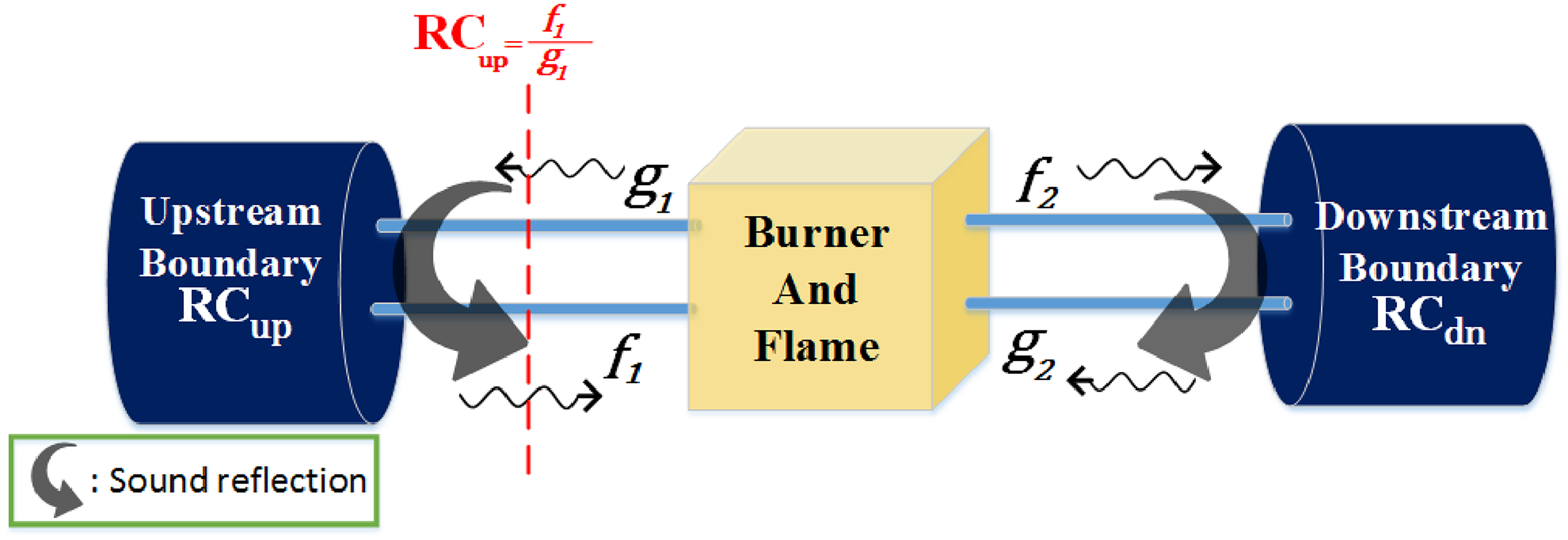
Acoustic wave propagation and reflection at the boundaries of a system.
In this context, an analogy between the methods of analysis of thermo-acoustic phenomena and a deeply developed theory used for the analysis and synthesis of radio-frequency electronic circuits has been recognized. Consequently, the methods and notions of general system theory of two-port network, can be applied to the problem of combustion instability. Among multiple fruitful approaches and concepts developed within the system theory, the present contribution is inspired by a useful concept which is widely used in the micro-wave circuit theory, namely the notion of an amplifier figure of merit.
The present contribution describes one of the constituting parts of a broader research program, performed within the framework of system theory and aiming to establish a way to introduce the notion of the thermo-acoustic quality factor of a given burner with flame. The ultimate goal of this program is to elaborate the concept of the thermo-acoustic figure of merit (quality indicator) to enable a comparative characterization of burners with flames in respect to their thermo-acoustic properties. The availability of such a notion may allow comparing and ranking different burners with flames with respect to each other. Furthermore, the maximization of this indicator may serve as the target function for development that is dedicated to the optimization of a burner design for improving its acoustic stability of operation.
The principal idea of defining the burner’s figure of merit was proposed by Kornilov and De Goey 9 and can be explained in the following manner: burner with flame “A” has higher thermo-acoustic quality in comparison to another burner with flame “B” if the probability of unstable operation of burner “A” is lower than the probability of instability of burner “B”. The probability of instability must be determined by comparing burner/flame stability based on tests performed with different acoustic embeddings (as if they are installed in different combustion appliances).
According to this definition, the figure of merit may be defined with respect to a certain class of (usually passive) acoustic embeddings which may reflect the typical properties (design features) of the appliances where the considered burners are used. In the broadest case, a field of arbitrary (but passive) acoustic embeddings can be considered to test the burners and determine their probability of instability.
An ideal burner with the maximum figure of merit would minimize the role of appliance/system boundaries. Therefore, such a burner would be the least problematic when incorporated in different appliances meaning at minimal risk to encounter an instability.
In literature the concrete implementations of the calculations of candidate parameters which promise to serve as the burner’s figure of merit are based either on theoretical derivations of indicators of the amplification factor, 10 or on passivity indicators, 11 or on (un)-conditional stability factors, 12 or on methods which use direct numerical tests performed in the spirit of Monte-Carlo simulation methodology with the corresponding statistical (pre-)post-processing of the simulation data.9,13
The proposition made by Polifke 10 adheres to the evaluation of the maximum possible amplification factor for the acoustic energy leaving the burner/flame with respect to any combination of incoming acoustic waves. Accordingly, the burner which has the capability to generate the smallest amount of acoustic energy must be treated as the best. This approach is inherently related to the transfer matrix (TM) singularity values. Its drawbacks and limitations were discussed by Hoeijmakers. 14
In another approach taken by Hoeijmakers et al., 15 a theory was developed which allows evaluation of the requirements (upper bound) for the adjoint acoustics when the flame TM is known. Particularly, the bound for the absolute values of upstream and downstream reflections was calculated, such that a given burner would be stable, irrespective of the phase of the reflection coefficients. In this way one may characterize the flame stability quality by comparing the requirements of unconditional stability imposed by the flame.
The third method to characterize the thermo-acoustic quality of a burner/flame represented by its transfer matrix was proposed by Kornilov and De Goey. 9 The core idea was to rank different burners represented by their flame transfer functions with respect to each other by evaluating the value of probability of (in)stability when the reflection at the system boundaries was randomly varied using the Monte-Carlo methodology. This idea was carried forward by Saxena et al. 13 where the reflection coefficient was formulated in terms of randomly selected strictly positive real functions (frequency dependent) instead of random constant values as in the former.
To the best of our knowledge no attempts have yet been made in literature to propose an experimental methodology where one can deduce some kind of estimate (indicator) of the burner’s thermo-acoustic figure of merit. The obvious difficulty of such an experimental method would be the need to arrange multiple tests of a given burner with flame in a broad field of variable acoustic embeddings of the system. This problem appears to be too tedious for practical implementation. However, the approach executed in the present research makes this task feasible. The developed experimental setup provides a viable solution for testing burners when they are integrated in a system with multiple, different, but well-defined acoustic environments.
The experimental setup can be seen in Figure 2 and the schematic of the setup can be seen in Figure 3(a). It is unique and its design uses a recently developed innovative technique to achieve a desirable reflection coefficient for an acoustic termination by Drolia 16 and Kojourimanesh et al 17 .
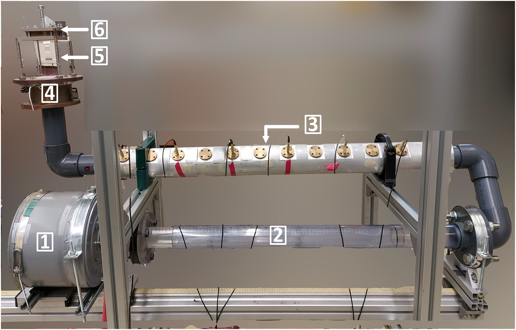
Experimental setup comprising of: 1. Cylindrical vessel with the upstream muffler placed inside it; 2. Telescopic tube with variable length; 3. Impedance tube incorporated with microphones; 4. Burner deck holder with water cooling channel; 5. Quartz tube placed on top of the burner deck holder and the burner under study and 6. Downstream termination placed on top of the quartz tube.
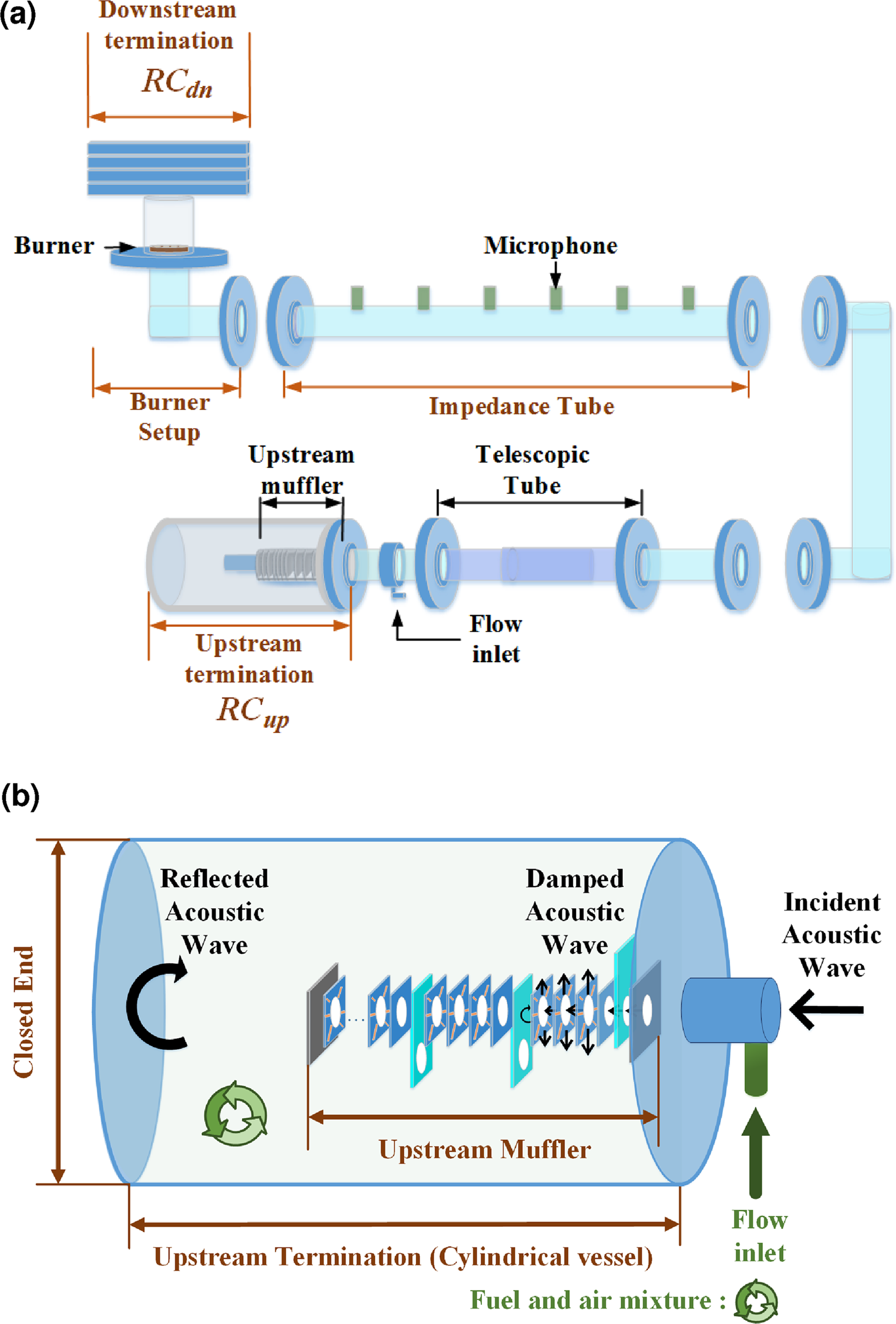
Schematic of the experimental setup and a close up of the upstream termination including the location and working of the upstream muffler. (a) Schematic diagram of the experimental setup. (b) Schematic diagram of the upstream termination.
Therefore, the aim of the present contribution is to introduce the conceptual idea of the experimental setup, describe its components including a detailed overview of the technical specifications and construction features to the extent which makes it possible to reproduce the working principle of this new experimental technique in different laboratories. The main output of the testing procedure is the mapping of the (in-)stability of operation of a given burner with flame in the field of variable absolute value of almost frequency independent reflection coefficients of upstream and downstream terminations and include a variable phase delay by the upstream termination. Accordingly, the burner’s figure of merit can be defined as the ratio of tests with stable operation to the total number of test cases.
For the downstream (hot) termination the desired magnitudes of RC ranging from 0.1 to 0.9 were successfully obtained by making a set of separate devices/terminations for each value. This set includes nine downstream terminations and each termination represents a particular magnitude and phase of RC. Each termination was tuned via iterative optimization experiments.
The upstream termination is a combined device which provides a way to switch the magnitude of RC with the help of some shutters which are conveniently placed and can be opened or closed providing control over the reflection coefficient magnitude. The telescopic tube (Figure 2) with variable length helps in achieving variable phase delay for the upstream part.
The performance of the setup will be demonstrated using, as an example, a particular type of perforated burner. The test case here consists of a burner with multiple Bunsen-type conical flames which are anchored on the perforated surface of the burner. Accordingly, the figure of merit will be defined for 4 burners with different perforation pattern (hole diameter and pitch) and different combustion power (flow rate and mixture equivalence ratios). Furthermore, several ideas of possible methods for the data post processing and interpretation will be introduced.
This paper is organised in the following manner: The following section consists of an itemized description of the experimental setup, followed by the details regarding the measurement techniques used in this study. To explain the working principle of the setup, a test-case study is presented in the subsequent section, where the stability maps of 4 burners are explored in an in-depth manner. Instead of representing the results of mapping of the system operation regimes with just binary indicators: stable or unstable, the observed behaviour is qualitatively characterised by introducing two more indicators: pockets of stability and beats. The difference between the four indicators will be elaborated in the results and is used in the presentation of the experimental results.
Experimental Setup
This section describes the experimental setup in terms of its construction and the objective of each part of the setup is explained. As can be seen in Figure 3(a), the experimental setup consists of the following parts: upstream and downstream terminations (Reflection Coefficient represented by RC
Upstream variable reflection coefficient termination
The prominent desired feature of the upstream termination was that it should provide an easy way to vary the magnitude of RC
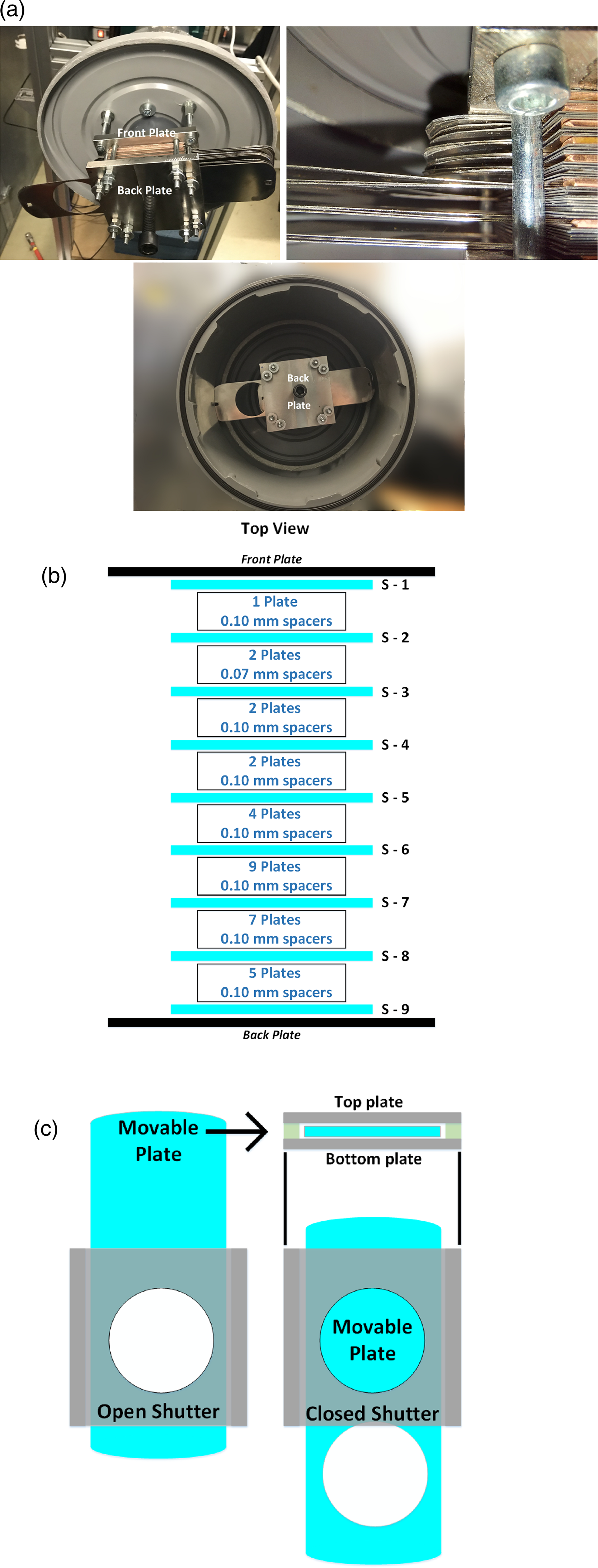
Parts of Upstream termination. (a) Upstream termination: Muffler outside the cylindrical vessel; close up of the muffler;muffler inside the cylindrical vessel. (b) Schematic of the upstream muffler along with the information about the plates, the shutters (S-Number) location and spacers used. (c) Working of the shutter assembly: Open and closed configurations.
Furthermore, the thinner plates and spacers are interlaced with shutters. Each shutter is made up of 2 plates (top and bottom plate, not to be confused with front and back plate of the upstream muffler) which are attached to each other at two opposite edges. The gap/separation resulting from the attachment between the top and the bottom plate allows the motion of a longer third plate in between them.
Experiments were performed to determine the optimal thickness of the movable plate as well as the shutter assembly such that when a shutter is inserted in between the stack of plates, it performs as an acoustically closed wall. There are two possible configurations allowed for the third movable plate as shown in Figure 4(c), one is open and another is closed. In the open shutter configuration, the acoustic wave may propagate further in the stack. In the closed configuration the part of the stack delimited by the shutter performs as an acoustical wave termination.
Nine such shutters are placed at different locations within the stack of 31 plates as shown in Figure 4(b). When all the shutters are closed, the shortest portion (volume) of the muffler device with the smallest number of plates in the stack is working and the magnitude of RC
Working of upstream muffler with respect to shutters (S-Number). (a) Open Shutter 1 (S-1) and Shutter 2 (S-2) result in volume up to Closed Shutter 3 (S-3) working to reduce the absolute value of Reflection coefficient (0.7). (b) Closed Shutter 2 (S-2) results in volume up to S-2 working to achieve the absolute value of Reflection coefficient (0.8).
To prevent leakage of the combustible mixture, the upstream muffler is installed inside a sealed cylindrical vessel, in other words the cylinder seen in the bottom of Figure 4(a) is closed and it acts similar to a plenum chamber while the experiments are performed. The dimensions of the vessel were chosen in a manner so that the RC
Downstream variable reflection coefficient terminations
While the upstream termination is one combined and compact setup/device, the possibility of constructing the same for the downstream termination was discarded for the simple reason that the hot exhaust gases and high temperature downstream would make it impossible to design a robust construction as well as forbid any motion of the third movable plates in the shutters, which is the main method to vary the value of RC
Each termination was made up of a different stack of plates and adjacent plates within a stack were separated by spacers of different thickness. Each stack represents a unique downstream termination and thus has a unique RC
Parts of Downstream terminations. (a) Downstream termination; Arrangement of spacers in between 2 adjacent plates. (b) All of the 9 downstream terminations.
After various trial and error experiments, frequency-independent, reflection devices with almost constant magnitude of RC
Downstream terminations.
Change in telescopic tube (TT) length
Since this experimental setup is a modification of the test rig from Saxena et al.,
18
the placement of the telescopic tube remained the same. The purpose of this tube was to allow variation in the phase of RC
Burners under study and quartz tube
The TT is followed by an impedance tube equipped with microphones. However, in the present study the results of the pressure measurement have not been incorporated and therefore it can simply be considered as a long tube of constant length before the burner deck holder.
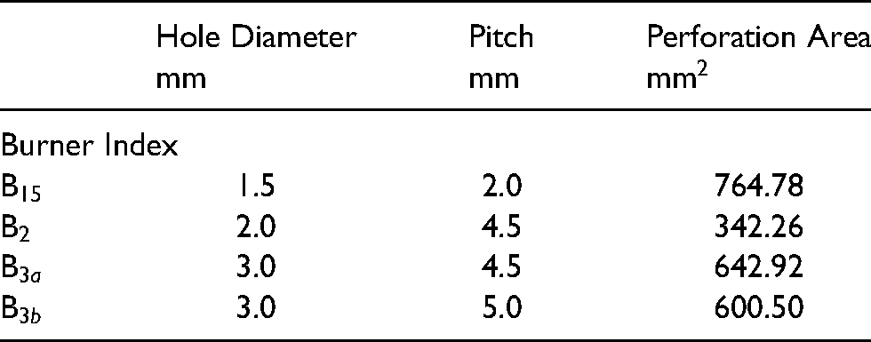
The water-cooled burner deck holder aides in maintaining the same temperature of the burner throughout an experiment. The burners are made of circular brass plates of 1 mm thickness with multiple holes (perforations) arranged in a hexagonal pattern as can be seen in Figure 7. These brass plates are referred to as burners in this paper. The burners were placed on top of the burner deck holder shown in Figure 2. Burners with hole diameters of 1.5 mm, 2 mm and 3 mm have been used in the present study. The details of the burners are shown in Table 2.
Burners under study (Burners B
Burner configuration.
A quartz tube with length of 110 mm and inner diameter of 50 mm is placed on the top of the burner to observe the flame. The inner part of the front plate of a downstream termination perfectly fits and rests on the top of this tube. The total length of the upstream part of the setup (i.e. excluding the quartz tube and downstream termination) is 305 cm when the length of the TT is fixed at 82.5 cm.
Applied measurement techniques and operating conditions under study
Reflection Coefficient measurement
The classic multi-microphone method, developed by Jang and Ih, 19 has been used to determine the reflection coefficient of different terminations. For the application of this method, 6 calibrated microphones (BSWA MPA416) are placed at an equal-distance from each other and are installed on an impedance tube of 1 m length. On one end of the impedance tube, a loudspeaker is positioned and on the other end, the sample whose reflection coefficient is to be measured is placed.
Excitations in the form of pure tone sine waves of a particular frequency are provided by the loudspeaker, resulting in acoustic pressure distribution along the impedance tube. When a sample is placed on the other end, the reflection of the acoustic wave varies the pressure distribution in the impedance tube. This new distribution is captured by the microphones, the data is collected using DAQ and controlled/processed using a LabVIEW program. The measured range of excitation frequencies is from 40 Hz to 800 Hz with a step increment of 20 Hz.
Finally, the collected time series data from all the microphones is post-processed to identify the incident and reflected acoustic waves. The acoustic pressure field is reconstructed using a MatLAB code and the reflection coefficient of the sample is obtained. The frequency-dependent reflection coefficient is the ratio of reflected to incident waves.
Process of observation and frequency measurement at system instability
Before supplying a mixture of methane and air to the experimental setup, a particular RC
In case the system is unstable, an external microphone is used to collect the data regarding the frequency of instability. The sampling length (bin size), rate and inbuilt FFT algorithm used by the external microphone leads to a frequency resolution of 3 Hz. The TT length is slowly changed and the corresponding effect on the system stability is noted. In the next step, the RC
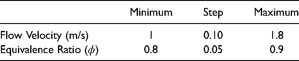
Operating Conditions.
Results and Discussion
RC
and RC
measurement results
The upstream termination (cylindrical vessel with the upstream muffler) was placed on the impedance tube setup, and the corresponding RC
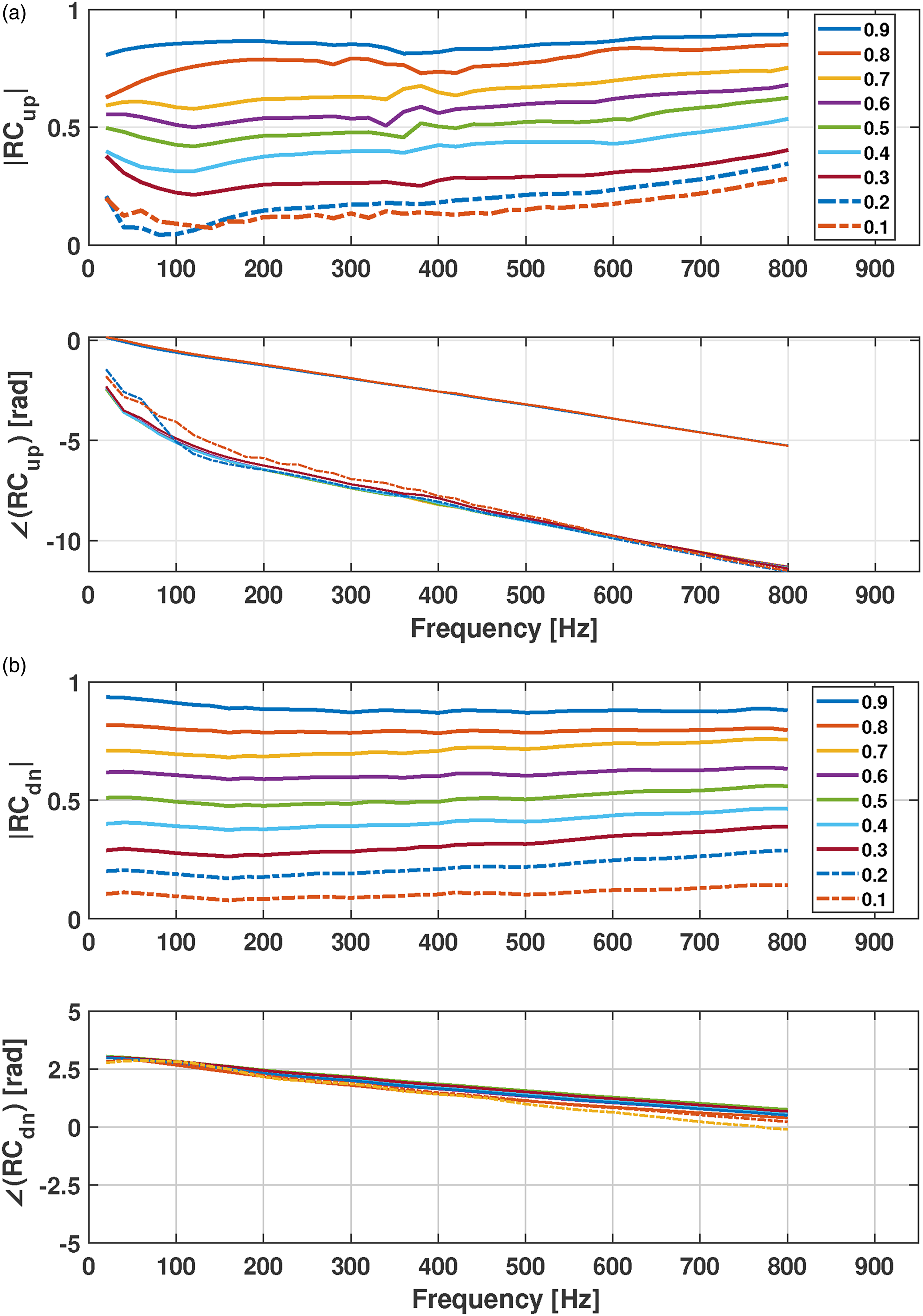
Upstream and downstream reflection coefficient. (a) Reflection Coefficient of Upstream termination: Magnitude and phase of the reflection coefficient for varying numbers of open shutters from all closed (0.9) to 8 shutters open (0.1). (b) Reflection Coefficient of Downstream terminations: Magnitude of the reflection coefficient (0.1-0.9) corresponds to individual termination (9 terminations in total).
Downstream terminations which were constructed separately are also almost frequency independent. The results of the measured magnitude and phase of RC
Demonstration of the experimental setup: Comparison of burners with respect to their stability maps
The methodology followed to measure the unstable frequency of a burner with flames for various combinations of upstream and downstream terminations has been explained in detail before. The remaining part of this contribution contains details regarding the demonstration of the experimental setup utilizing four different burners. The dimension of the explored space of varied parameters is 3 (RC
Case 1 (green filled circle) is when the flame was initially stable (when the TT length is 0 cm) and stayed stable as the TT length was varied from 0 to 70 cm.
Case 2 (black asterisk) is when the flame is stable for some range(s) of TT length and unstable for another range(s). This situation will be referred to as the presence of ‘pockets of stability’. The unstable frequency oscillations maybe tonal or having beats containing 2 or more frequencies. Noiray et al.
20
noticed this difference in widths of unstable combustion region for 2 different burner thicknesses (3 mm and 30 mm) as a function of upstream resonant duct depth. Since the Burners B
Case 3 (black square) is when the flame is unstable from 0 cm of the TT length to 70 cm, without any pocket of stability, and produces only a tonal sound of a certain frequency, generally referred to as steady-state limit cycle cases.
Case 4 (black triangle) is when the flame is unstable, similar to Case 3 but instead of producing only tonal sound, there is also a range(s) of the TT length where beats are observed. The reason for distinguishing the Case 3 and Case 4 is to retain information about the way the limit cycle of instability would behave when the upstream or downstream RC magnitude is varied in more detail and obtain a trend that maybe followed by the flames.
Figure 9 shows the stability maps of Burners B
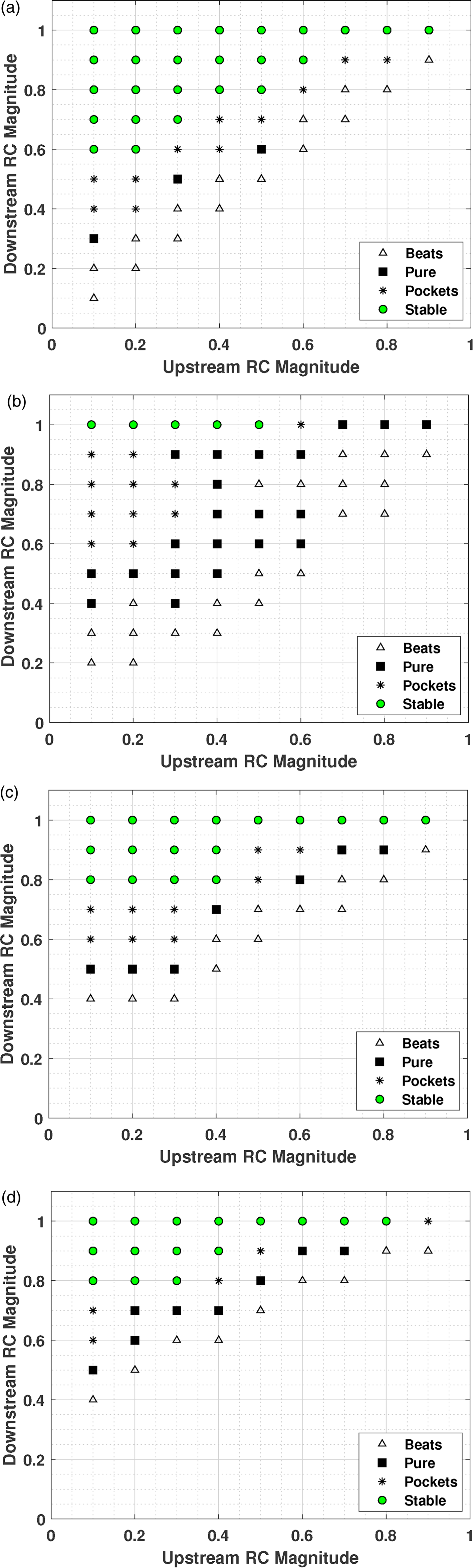
Symbols for the stability maps are as follows: Green filled circle: Case 1 (stable for all values of TT length); black asterisk: Case 2 (having pockets of stability); black square: Case 3 (tonal frequency) and black triangle: Case 4 (beats phenomenon). Measurements were made at main approaching flow velocity of 1.2 m/s and at equivalence ratio of 0.8. (a) Stability map of Burner B15. (b) Stability map of Burner B2. (c) Stability map of Burner B3a. (d) Stability map of Burner B3b.
Analysing the maps one may notice that, at the given flow setting (inlet flow velocity of 1.2 m/s and at equivalence ratio of 0.8), the burner B
The development of an experimental technique which would allow measurement of a burner’s stability in the space of parameters (characterized by the acoustic embedding) and consequently help in evaluating a burner’s figure of merit was the main objective of the present contribution and it is successfully achieved. When this experimental technique is compared to theoretically proposed indicators, the advantages of the setup standout. The novel experimental methodology and results presented in this paper provide a quantitative value for the figure of merit for the tested burners which was yet to be determined experimentally. The results from this paper can further be used to validate the models proposed before which depend on statistically evaluating the figure of merit using Monte-Carlo simulation.9,13 By constructing a setup, where the reflection coefficient is weakly dependent on frequency and testing all the data points in stability map (RC
Below a few examples of possible directions for further analysis are presented.
It is interesting to note the trend followed by the operation dynamics when the RC
Now if the same trend is followed for the Burner B
Using these stability maps, the effect of burner configurations on the system stability can also be traced. For example, the Burners B
As the magnitude of RC
The essence of the burner intrinsic thermo-acoustic instability mode is that even if the losses at the boundaries are high and external acoustic feedback (waves propagating to the burner from upstream and downstream directions) is absent, the internal feedback makes the flame on the burner perform as a source of waves. This mode can be stabilized by embedding the burner in-between certain terminations. In the above-mentioned case of Burner B
The available data can also be analysed to reveal trends when the third parameter of the parametric space is varied. Particularly, to analyse the effects of change in the TT length, one may consider the RC
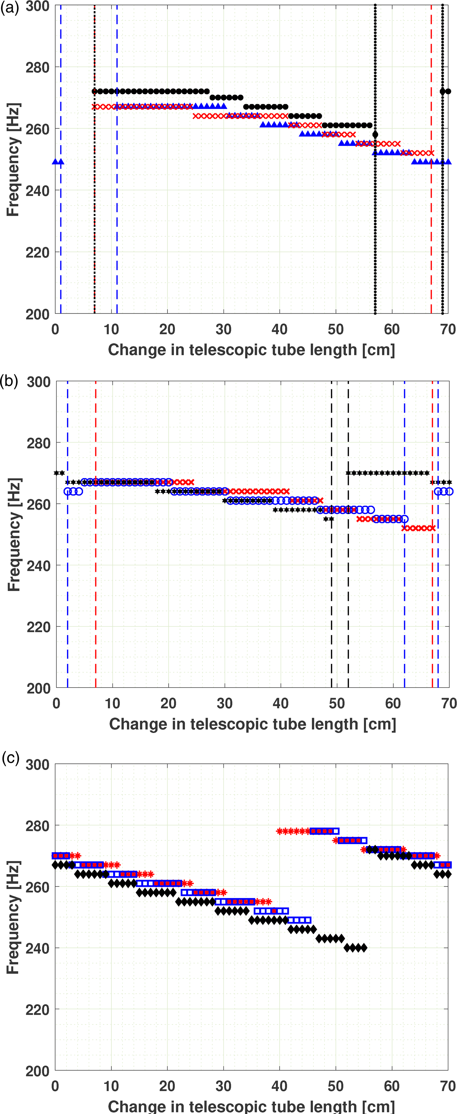
Variation of frequency of instability with respect to change in telescopic tube length for Burner B
For Burner B
A similar analysis on the effect of change in the TT length can be done for any/all points in the stability maps shown in Figure 9. After performing this kind of analysis for the burners considered above, it can be hypothesized that the pocket of stability is the precursor of upcoming switch of the dominant modes of unstable frequency as the tendency described above was observed for the stability maps of all the burners.
Effects of change in inlet velocity and equivalence ratio on flame stability
For consistency all the above mentioned studies were performed keeping the flow operating conditions constant. The inlet flow velocity of fuel and air mixture in the perforation holes was kept at 1.2 m/s and the equivalence ratio (
Results of the experiments show that an increase in the inlet velocity results in an increase in frequency of instability at a fixed value of the TT length as shown in Figure 11(a), for example, when the length of the telescopic tube is fixed at 20 cm, and the inlet velocity is increased from 1.2 m/s to 1.5 m/s, the unstable frequency increases from 267 Hz to 281 Hz. Further increase in inlet velocity to 1.8 m/s results in an increase in unstable frequency to 302 Hz. There were also cases when a stable flame became unstable due to increase in velocity. Inlet velocity change showed no hysteresis, and the results were repeatable. In the cases where the system experienced beats phenomenon (Case 4), the increase/decrease in velocity lead to the disappearance of beats and tonal sound was produced by the flame. The pockets of stability also tend to disappear with increase in the inlet flow velocity.
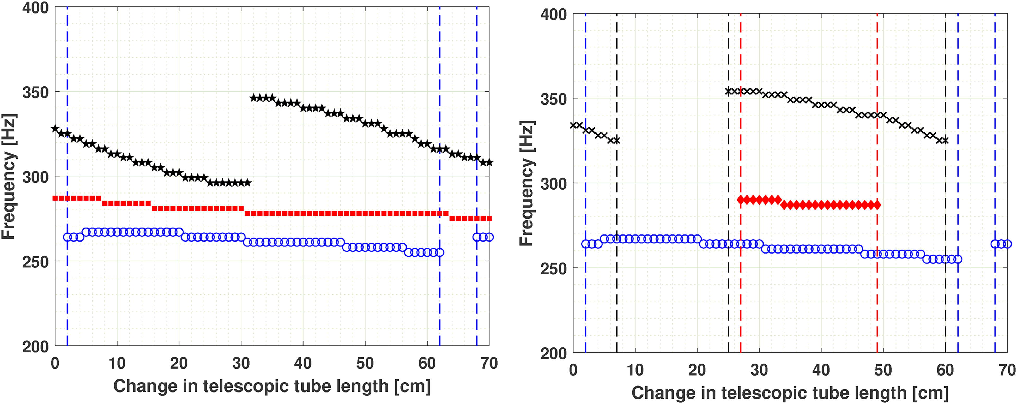
Variation of frequency of instability with respect to change in telescopic tube length for Burner B
The effect of increasing
Conclusions
In the present contribution, the design, construction and usage of a new setup which allows testing the phenomena of thermo-acoustic instabilities in a combustion device are introduced. The unique feature of the setup is the possibility to vary the reflection coefficients at the acoustic boundaries of a burner/flame. The magnitude of the reflection coefficients are almost frequency independent in a wide range of frequencies (including the low frequency limit). Furthermore, the setup allows independent variation of the phase of the upstream reflection.
The achieved variation range of magnitudes of reflection coefficients is from 0.1 to 0.9 for both upstream and downstream terminations in the frequency range 40–800 Hz. The additional option to vary the length of the TT (0–70 cm) provides further flexibility to control the phase of the burner upstream reflection. The paper contains a detailed overview of the setup, which makes it possible to assemble the setup at another laboratory and perform experiments of the similar kind.
The idea behind the setup is to allow an experimental mapping of stability-instability regions for given burners/flames in the space of reflection coefficients as the parameters of the burner acoustic embeddings. The mapping is then used to evaluate the thermo-acoustic behaviour of several burners with flames and different burners/flames are compared with each other in respect to their figure of merit. Therefore, the notion of the burner/flame figure of merit is evaluated experimentally.
The usage of the setup is demonstrated for four burners which have some similarity in terms of their burner geometry parameters.
The performed analysis of the (in-)stability maps of the flames under various operating conditions demonstrates a possibilities to elucidate correlations which may provide an extra understanding regarding the burner’s thermo-acoustic properties and its figure of merit particularly.
Since the results produced are promising, further study can be performed using multiple burners, incorporating the impedance tube placed on the setup to study the modes of the encountered unstable regimes of operation of different burners. Moreover, this setup will also provide ways to validate analytical models and thus result in achieving a wider range of applications.
Footnotes
Acknowledgements
This work is part of the Marie Skłodowska-Curie Initial Training Network
The authors gratefully acknowledge our teammate, Mohammad Kojourimanesh, for his help in preparing the test setup.
Declaration of Conflicting Interests
The author(s) declared no potential conflicts of interest with respect to the research, authorship, and/or publication of this article.