
Abstract
Additive manufacturing is an option for the fabrication of heat exchangers for thermoacoustic applications. In thermoacoustic devices, heat exchangers are placed in oscillatory flow. A careful consideration of heat exchanger geometries examines the application of methodologies to optimise heat transfer and the temperature gradient. Additive manufacturing is proposed as an alternative fabrication technique that can overcome the current limitations of conventional fabrication machining. Six identical crossflow heat exchangers were made and tested, three from stainless steel and three from aluminium. The oscillatory flow moves back and forth through circular cross-section channels, and water flows in channels perpendicular to them. Heat transfer and temperature gradients were investigated at different drive ratios and mean pressures.
Keywords
Introduction
Heat exchangers play an essential role in imposing a temperature gradient through the porous medium of a thermoacoustic application, which promotes the thermoacoustic phenomenon. The phenomena amplify the acoustic power through a porous medium induced by a temperature gradient or imposed on the medium by utilising the acoustic power. Depending on the application, thermoacoustic devices can be classified as engines (prime mover) or refrigerators (heat pumps). Engines use heat energy of low, medium or high quality to generate or amplify acoustic power.1,2 Whereas, refrigerators convert the acoustic power into cooling to a temperature that can be below the freezing point of water.3,4 The temperature gradient is maintained by heat exchangers adjacent to the porous medium. The heat exchanger’s ability to maintain the temperature gradient is a crucial limitation to the performance and development of thermoacoustic devices. Additionally, exchangers are the most expensive element to fabricate within the thermoacoustic setup.
Many heat exchanger configurations have been previously fabricated using traditional machining techniques. The majority of these heat exchangers were of the crossflow type, having an oscillatory flow on one side and a cooling or heating fluid on the other. Some have heaters instead of heating fluids. Drilling through a block of material can form flow passages for both oscillatory and cooling/heating fluids. Piccolo et al. 5 drilled 574 holes at a diameter of 2.5 mm in the oscillatory flow, which makes the porosity of the heat exchanger 67%. Zare and Tavakolpour-Saleh 6 machined 1.8, 4 and 6 mm holes in the hot and cold heat exchangers. Kruse et al. 7 used copper blocks with 3 and 4 mm holes, giving 39%–59% porosity. Saechan and Jaworski 8 used 3 and 5 mm drills to fabricate the ambient and cold heat exchangers, while 8 mm holes were used for a shell-and-tube hot heat exchanger.
Another fabrication method is to braze plates to the heat exchanger walls, which allows a higher gas-to-metal contact area. Piccolo et al. 5 brazed 0.35 mm-thick copper plates at a spacing of 1 mm, which offered 55% porosity. A thinner copper plate of 0.1 mm was researched by Smith et al. 9 Short fins of 1 mm height and 50 fins per inch were brazed in the hot heat exchanger by Tijani and Spoelstra. 10 Contact between the brazed fins and the heat exchanger walls is not sufficient to transfer enough heat between the gas and metal. Therefore, a parallel plate cut through a block of metal using EDM (electrical discharge machining) has been adopted. This offers high gas-to-metal contact and good heat transfer between the fins and heat exchanger block. Sharify and Hasegawa 4 cut 1 mm fins with a spacing of 2 mm, while Tan et al. 11 used a 1.5 mm spacing. In another application, Tan et al. 12 machined 0.8 mm fins and spacing. Yahya et al. 13 built a thermoacoustic refrigerator with heat exchangers having a fin thickness of 0.5 mm at a 1 mm gap.
Additive manufacturing and 3D printing offer an alternative approach to building heat exchangers or porous media for thermoacoustic devices. Ramadan et al. 3 used additive manufacturing to build a finned tube heat exchanger made of aluminium. Hathaway et al. 14 investigated the possibility of building a commercial-scale heat exchanger using additive manufacturing. AM helped to investigate new characteristics such as internal fins and externally angled fins. Kirsch and Thole 15 developed microchannels for heat sinks. The microchannel configuration was wavy. Four channel arrangements were studied, two of them separate, and two mixing channels. Collins et al. 16 applied the potential of AM to fabricate a heat exchanger with microchannels. The study compared the pressure drop and heat transfer of manifold microchannels and permeable membrane microchannels. Yilmaz and Ugla’s 17 review covered the applications of different techniques of additive manufacturing. The fins can be formed out of lattice, which offers more fluid-to-metal contact area and some control on pressure drop.18–20 The freedom of AM allows a wide range of lattice configurations, from a simple face-centred cube to very complicated patterns. Elkholy and Kempers 21 used AM to apply surface modifications to enhance the heat transfer rate. The modification increased the heat transfer coefficient by nearly 80%.
In thermoacoustic applications, the potential of manufacturing a stack (porous medium) using AM was investigated. Auriemma and Holovenko 22 examined many configurations of stacks built with stainless steel using AM technology. The tested configuration includes parallel plates and stacks with internal oblique pins, which are difficult to fabricate using conventional technologies. Others have employed additive manufacturing to print a stack in a diamond unit cell and longitudinal pin lattice structure. 23 Almusaied and Asiabanpour, 24 compared the performance of stacks built using fused deposition modelling (FDM) and stereolithography (SLA) printing technologies. The stacks were built using acrylonitrile butadiene styrene (ABS). Di Giulio et al. 25 used stainless steel AISI 316L powder particles whose sizes ranged from 10 to 45 μm to build lattice structures forming a stack.
This paper offers the first experimental testing of heat exchangers built using additive manufacturing in oscillatory flow. Two materials were tested in a pressurised resonator: aluminium and stainless steel, and a performance comparison was examined.
Heat exchangers in oscillatory flow applications
The design of heat exchangers is a dominant parameter with regard to the performance of thermoacoustic and pulse tube cooler applications. A properly designed heat exchanger would ideally meet the heat transfer requirement with minimum acoustic power loss and pressure drop. The design’s influential parameters are gas-to-solid contact area, material, porosity and spacing. The first three parameters are common for uni-directional and bi-directional flow; a preferred heat exchanger should deliver the highest possible gas-to-solid contact, be made from a high thermal conductivity material, and have the highest possible porosity. The spacing factor has special consideration in oscillatory flow, as will be discussed in the following paragraphs.
The two main heat exchanger fabrication challenges for oscillatory flow applications are pressure endurance, and the
Designing the heat exchanger to endure high pressure needs careful consideration. The majority of the fabricated heat exchangers are cross-flow heat exchangers or they are machined to accommodate electrical heaters. These heat exchangers have oscillatory flow through a set of channels, water or air flow through perpendicular channels, or alternatively, electrical heaters inserted through the prepared holes. These heat exchangers experience a pressure difference between the internal elevated mean pressure and the external ambient pressure through the separation walls. As such, this pressure difference risks catastrophic wall rupture. The ambient pressure channels or heater holes are normally circular or finned-rectangular channels. The conventional drilling or EDM technologies used make it difficult to build supports throughout the channels, which limits the allowable pressure difference and increases the separation wall thickness between the channels. A serious challenge is designing hot heat exchangers, as metals suffer reduced strength at high temperatures, which reduces their ability to endure pressure.
The ratio of the hydraulic radius (rh) to the thermal penetration depth
For conventional machining and EDM, it is hard and costly to cut channels at a diameter or spacing of less than 1 mm. For helium for example,
Each heat exchanger has porosity. The porosity of interest in the research is the porosity of the oscillatory flow side. Both cross-flow and embedded heat exchangers have quite low porosity, as almost half of the cross-sectional area on the oscillatory flow side is blocked to accommodate the channels of the other side’s flow or heater holes. Low porosity increases viscous losses as it increases the velocity and displacement amplitude inside the exchanger. 26 This increases the pressure drop and acoustic power loss throughout the heat exchanger. The low porosity limits the channel cross-section area, which limits the gas-to-metal contact area and, hence, the heat transfer capacity of the exchanger. Long peak oscillation and small gas-to-solid contact require increasing the exchanger length in the direction of the oscillatory flow, which increases the pressure drop and acoustic power loss. Ideally, the exchanger length is one to two peak-to-peak displacements.
Additive manufacturing potential in oscillatory flow applications
Metal additive manufacturing is a relatively new manufacturing process that, by its bottom-up, layer-by-layer nature, offers the possibility of overcoming many of the design constraints placed on possible heat exchanger geometries (Figure 1). The process uses either a CNC-controlled laser or an electron beam to fuse metal powder at discrete locations on a 2D plane as guided by a CAD design. After each 2D layer is completed, a fresh layer of powder is deposited, and the process repeats thousands of times until the component is ‘built’. The following section briefly reviews the AM in the context of producing complex geometries.
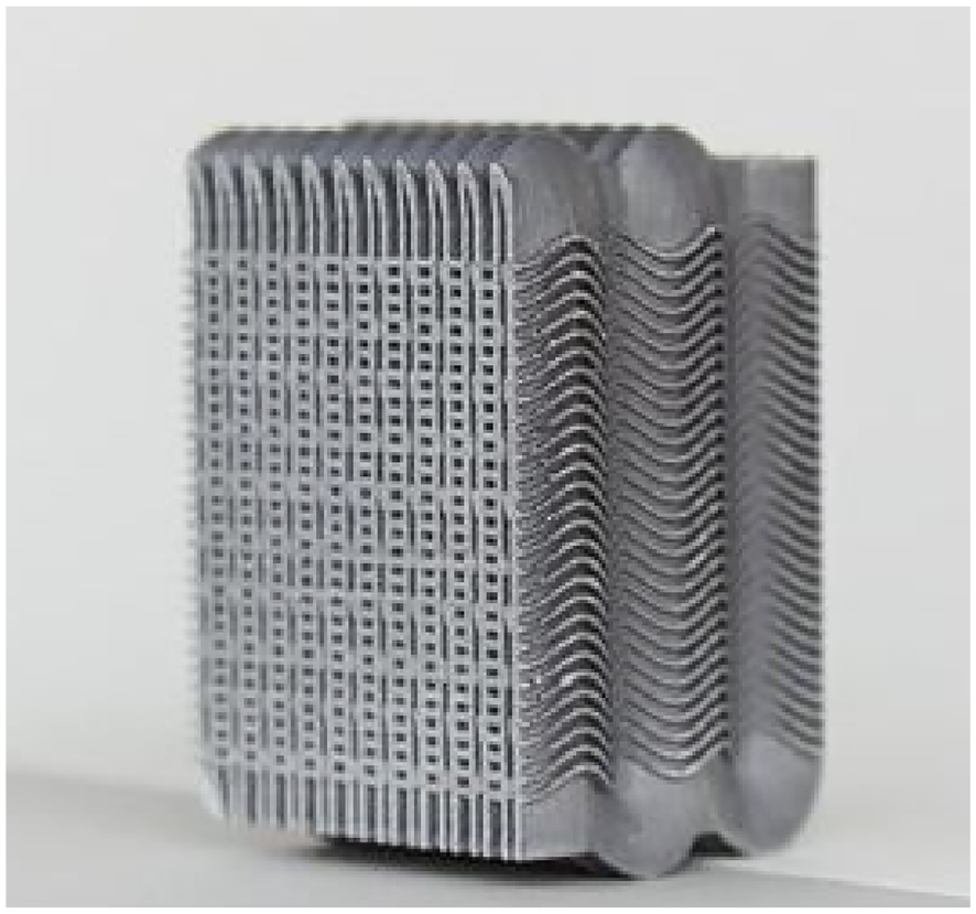
Generic 3D printed heat exchanger (https://www.eos.info).
The potential of applying additive manufacturing (AM) to building heat exchangers for oscillatory flow applications can be classified into two categories. The first is to improve the exchanger parameters that were designed based on the available machining techniques. The second is to develop configurations that were previously impossible to build using available traditional subtractive machining techniques.
The heat exchanger design challenges and the parameters of the currently available techniques reviewed in Section ‘Heat exchangers in oscillatory flow applications’, will be discussed from an additive manufacturing point of view. The first design challenge to be reviewed is pressure endurance. The explosive failure of an exchanger due to the pressure difference between the oscillatory flow and ambient (channels or heaters) is currently avoided by increasing the separation wall thickness and reducing the ambient side channel width. Increasing the wall thickness reduces the exchanger’s porosity. Machining narrow channels limits the fluid-to-metal contact and increases the machining cost. AM allows the building of channel supports along the ambient side channels. In addition, AM allows the manufacture of a series of narrow channels (less than 1 mm), each having round edges, leaving narrow supports between channels. Any of these two leads to minimising the wall thickness. This increases the exchanger porosity while allowing more fluid-to-meal contact by increasing the cross-section of both ambient and oscillatory flow channels.
The channels on the oscillatory flow side can benefit from AM by enhancing the heat exchanger’s porosity, gas-to-metal contact area and
AM can build configurations that were hard or impossible to make, using available subtractive machining techniques. There are unlimited configurations and arrangements to ensure heat exchangers have high gas-to-metal contact at low porosity and length, yet are designed for elevated pressure differences. One such configuration will be suggested in this paper.
It is possible to make the channels on both flow sides have pin fins. Pin-arrangement heat sinks are widely studied both theoretically and experimentally.24,25 However, it is not thoroughly studied at the millimetre scale in oscillatory flow. With currently available subtractive manufacturing techniques, it is hard to build inner channels formed of fin pins at a spacing of
Experimental set-up
To validate the use of additive manufacturing for building heat exchangers for oscillatroy flow applications, two sets of heat exchangers were made and tested. The heat exchangers are replicas of research published by Ilori et al.30,31 and were tested in the same setup. The heat exchangers were tested in oscillatory flow conditions to validate their suitability to replace those made by conventional machining.
It is worth highlighting the progress of the work presented in this paper compared to the research published by Ilori et al.30,31 First, the current work is to test heat exchangers made using Additive Manufacturing in oscillatory flow conditions. Second, the current study confirmed that heat exchangers made using the AM technique overcome assembly and gas leakage issues faced by Ilori et al.30,31 Third, AM enabled building supports (structural reinforcement) inside heat exhanger channels to enhance the pressure endurance – something that would not have been possible with conventional subtractive technologies. These will be explained in the next section.
Heat exchangers
Three materials were considered in this project: aluminium, stainless steel and inconel. Only aluminium and stainless steel were available at the time of printing. However, Inconel is regarded as suitable for the next project, due to the benefits highlighted by Wang et al. 32
Six identical heat exchangers were made using additive manufacturing. Three are made from 316 stainless steel and three from aluminium. The heat exchangers are cross-flow heat exchangers, having oscillatory flow through a circular section and water flowing in channels perpendicular to it. On the oscillatory flow side, the heat exchangers are identical to those previously built by conventional machining. However, some of the advantages of additive manufacturing were applied to other design elements.
The previous heat exchangers consisted of a heat exchanger block, face edge attachments, housing mounts and tube fittings. In this research, all these parts are printed as ‘monobloc’ one-piece components. This helps to avoid the complex assembly procedures and leak-fighting processes. Added to that, channel supports were introduced to the water channels and sides to avoid explosive failure, as the mean pressure in oscillatory flow channels is higher than the water channels. Figure 2(a) shows a sectioned CAD drawing of the heat exchanger.
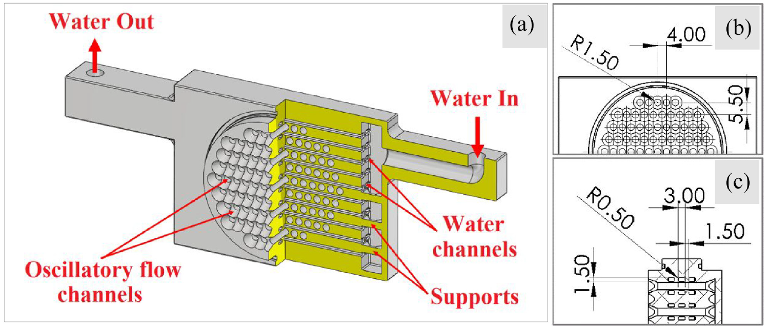
(a) A sectioned CAD drawing of the AM heat exchanger, (b) dimensions of oscillatory flow channels and (c) dimensions of water channels.
The heat exchanger diameter is 57.5 and 20.5 mm long on the oscillatory flow side. It has 89 holes, each hole is 3 mm in diameter, as shown in Figure 2(b). This is equivalent to 24.4% porosity on the oscillatory flow side. The holes are arranged in-line 4 mm apart, and the lines are 5.5 mm from each other, with both distances measured centre-to-centre. Each side has an ogive protruding edge of 4 mm. On the water flow side, there are 15 channels arranged in five lines passing between the oscillatory flow holes, as shown in Figure 2(c). Each water channel is 3 mm wide and 1.5 mm high. Surface roughness varied at the channels is within the standard SLM range of 25–30 µm.
A Renishaw AM 400 was used for the 3D printing and to allow the building of the structures, a 45° build angle was used (Figure 3(a)). For aluminium exchangers a AlSi10Mg alloy was used (per manufacturer recommendation) with a 400 W laser power and a 25 µm layer thickness. For the stainless steel exchangers a stainless steel 316L alloy was used, having a 50 µm layer thickness and using 200 W laser power (per manufacturer recommendation). A completed build is shown in Figure 3(b).
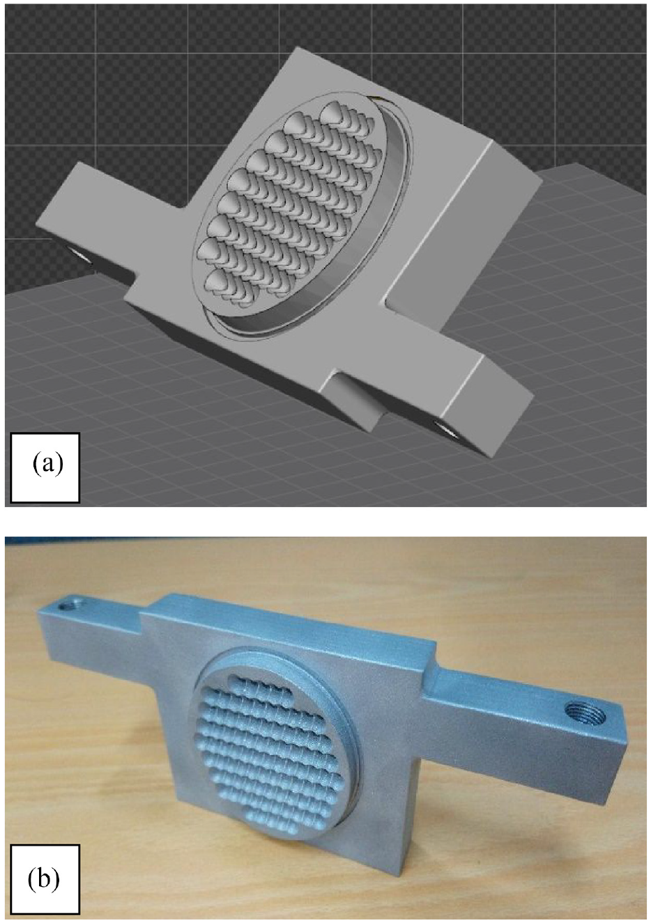
(a) Component shown in CAD at 45° build angle and (b) AM built heat exchanger.
Testing apparatus
The heat exchangers were tested in oscillatory flow. Each set of three was arranged in-line, as shown in Figure 4(a). The middle exchanger was heated using water at 80°C, and the other two were cooled down using water at 20°C (same arrangement as Ilori et al.30,31). The exchangers were connected 6 mm apart. The temperature of the hot water bath is maintained by a domestic water heater (model DM868, by buffalo), and the cold water temperature is maintained by an industrial chiller (CW-5000 by S&A).
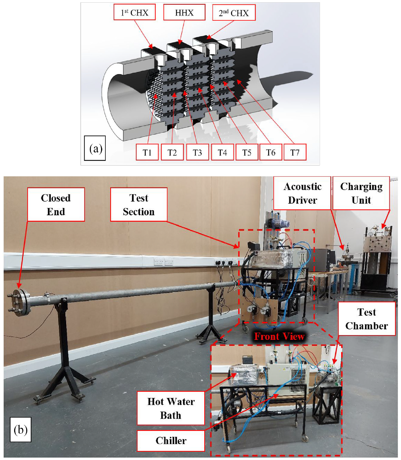
(a) A CAD cross-section of the set of three heat exchangers and (b) experimental rig.
The exchangers were placed inside a half-wavelength resonator filled with helium. The resonator is 50.8 mm (2 inch) in diameter and 9 m long. It has one end closed and an acoustic driver located at the other end. Figure 4(b) shows the experimental setup. The driver is a Q-drive (Model: 1S132DX). It is able to generate up to 225 W of acoustic power and has a peak piston displacement of 7.15 mm. The heat exchanger set was placed 4.28 m from the driver, which is around 0.24λ.
Twenty-one k-type thermocouples were used to measure the temperature of helium and water. Sets of three thermocouples were placed before the first heat exchanger, between each two, and after the last exchanger at a distance of 3 mm. Six thermocouples were placed in the water channels at the inlet and exit of each heat exchanger, and three inside the oscillatory flow channels of the heat exchangers. The pressure was measured using PCB PIEZOTRONICS pressure transducers model 112A22. The apparatus has five holding ports, one at each end and three in the middle. A signal conditioner, PCB PIEZOTRONICS model 480B21, was used to power the transducer and generate a useful pressure signal that could be monitored. All the thermocouples and pressure transducers were connected to a data acquisition card, OMEGA OMB-Daq, which logs the data for LabVIEW. The piston displacement was monitored using a LK G152 displacement sensor. It uses a laser beam that it points at the back of the driver’s mass through a high-pressure sight glass.
Results
The acoustic performance of the resonator was first investigated. In this test, mean pressure and the driver’s piston peak displacement were the independent variables. The rig was charged with helium. The charging procedure included evacuating and charging the rig (up to 3 barg) twice to eliminate any trace of air, then charging to the required pressure the third time.
The half-wavelength resonator is expected to have two pressure amplitudes at the ends. Figure 5 shows the pressure amplitude and drive ratio distribution along the resonator at different mean pressures. The drive ratio is the ratio of the pressure amplitude to the mean pressure. The pressure sensor at
Pressure distribution and drive ratio along the test rig as a function of mean pressure at 6 mm piston displacement.
The effect of excitation piston peak displacement is investigated and shown in Figure 6, all tests were at 5 barg. It shows that increasing excitation displacement leads to increasing the pressure amplitude and drive ratio. Unlike the mean pressure, the increase in pressure amplitude leads to an increase in drive ratio as the mean pressure remains constant in this test. The maximum recorded pressure amplitude of 6001 Pa at 5 barg mean pressure and 6 mm piston displacement and the maximum drive ratio of 10.85% at ambient pressure and 6 mm piston displacement, recorded at the closed end of the resonator.
Pressure distribution and drive ratio along the test rig as a function of peak piston displacement at 5 barg mean pressure.
The thermal performance of the built heat exchangers was tested by measuring the heat transfer and temperatures at different excitation peak piston displacements and mean pressures. As explained in Section ‘Testing apparatus’, the heat exchangers are heated up and cooled down by water and there are thermocouples placed in the water stream before and after the heat exchangers. The water flow of all heat exchangers was set at 0.7 L/min. The heat transferred to the heat exchanger was then calculated using the measured temperatures and water flow. The heat transfer value is a combination of the amount of heat transferred between heat exchangers, heat lost through conduction and heat lost to the surrounding area through oscillatory flow. Both stainless steel and aluminium heat exchangers were tested.
Figure 7 shows the heat transferred through heat exchangers (stainless steel and aluminium) at various mean pressures and drive ratios. The six tested drive ratios correspond to 1–6 mm piston displacement. The drive ratio is the drive ratio in the test section. The positive heat values are the heat transferred through the hot heat exchanger, and the negative is the algebraic sum of the heat transferred through the two cold heat exchangers. The heat transferred from the hot heat exchanger is always higher than the cold heat exchangers due to thermal losses.
Heat transfer versus drive ratio at different mean pressure: (a) steel heat exchangers and (b) aluminium heat exchangers.
Figure 7 shows that the heat transfer through aluminium heat exchangers is higher than the steel, due to the higher thermal conductivity of aluminium. The test shows that at a specific mean pressure, increasing the driving ratio 3–4 times is able to increase the heat transferred up to three times. The lost heat is the algebraic difference between the positive and negative marker values, at a given mean pressure and drive ratio. The thermal losses increase with increasing the drive ratio at a certain mean pressure. This is attributed to a higher displacement amplitude of the gas leaving the cold heat exchanger at a higher drive ratio, which transfers heat away from the cold heat exchangers.
Oscillating helium temperatures were measured at seven different locations, labelled 1–7 in Figure 4(a). The temperatures in locations 1, 3, 5 and 7 were measured using three thermocouples, and the presented temperature is the average of the three readings. T1 and T7 are located before the ambient heat exchangers, while T3 and T5 are located between the hot and ambient heat exchangers. T2 and T6 measure the helium temperature inside a channel in the cold heat exchanger, and T4 measures the temperature inside the hot heat exchanger.
Helium and water temperatures were logged for every test. The heating and cooling water were kept at 80°C and 20°C, respectively, during all the tests. The helium temperature in the core is dominated by the drive ratio and mean pressure. Figure 8 shows the temperature distribution for the range of the drive ratio and the mean pressure range of 1–5 barg, for both aluminium and stainless-steel heat exchangers. Figure 8 reveals that increasing the drive ratio affects the temperature values of the hot and cold ends due to enhanced heat transfer. For example, when the temperature difference between hot and cold aluminium heat exchanger is 44.5°C at 0.51% drive ratio and 5 barg, it drops to 28.7°C at 2.17% drive ratio and 5 barg, as shown in Figure 8(b). Increasing the mean pressure has the same effect of increasing the mean pressure. For example, when the temperature difference between the hot and cold stainless steel heat exchanger is 38.7°C at 2.64% drive ratio and 1 barg, it drops to 32.1°C at 2.17% drive ratio and 5 barg, as shown in Figure 8(a).
Measured helium temperature at various locations versus drive ratio, (a) and (c) are for steel heat exchangers at 1 and 5 barg, (b) and (d) are for aluminium heat exchangers at 1 and 5 barg.
The drop in helium temperature inside the channels of the hot heat exchanger at variable mean pressure is dependent on the heat exchanger material. The temperature of the stainless-steel hot heat exchanger dropped from 64.8°C to 59.3°C when increasing the drive ratio from minimum to maximum at 5 barg, while it dropped only from 66.3°C to 62.7°C in aluminium, as shown in Figure 8.
To compare the thermal performance of AM and conventional manufacturing, the results of the current study could be compared to those of Ilori et al.30,31 who used similar heat exchangers. Both heat transfer and temperature distribution of the AM aluminium set, and Ilori et al.,30,31 are similar.
Conclusion
The application of additive manufacturing to replace conventional manufacturing was investigated. To demonstrate the application, heat exchangers were built and tested in oscillatory flow at a mean pressure higher than ambient. This study showed the benefits of using AM to overcome some manufacturing and assembly challenges. The experimental investigation showed that AM can successfully replace heat exchangers built using conventional manufacturing methods.
Limiting heat transfer factors affecting oscillatory flow were identified, and AM was proposed as a vital solution for them. For experimental validation, a set of heat exchangers made from stainless-steel and another from aluminium were built using AM and tested in oscillatory flow. The heat exchangers made from both stainless-steel and aluminium withstood the elevated pressure difference, however, the thermal performance of the aluminium heat exchangers outperformed the stainless-steel heat exchangers. The results confirmed that AM is a valid fabrication technique for oscillatory flow heat exchangers.
Results also demonstrated the relationship between heat transfer and mean pressure at a range of 0–5 barg, and the relation between heat transfer and drive ratio of up to 2.7%. The thermal behaviour of the AM heat exchanger is quite similar to that of conventional machining-built heat exchangers.
Footnotes
Declaration of conflicting interests
The author(s) declared no potential conflicts of interest with respect to the research, authorship, and/or publication of this article.
Funding
The author(s) disclosed receipt of the following financial support for the research, authorship, and/or publication of this article: The authors would like to thank EPSRC (UK) for funding this research under grant EP/R023328/1.