
Abstract
Autonomy is considered an important criterion that characterizes the performance of electric vehicles. It is represented by the distance that could be traveled by a fully electric vehicle which mainly depends on several parameters such as the vehicle model, type of battery, type of motor, etc. In this context, to improve the autonomy of electric vehicles, this paper represents an optimization study for the electric motor based on two contributions. The first devise an energy optimization algorithm to reduce the motor losses by calculation of the stator flux reference according to the electromagnetic torque and the rotation speed. The second is concerned with controller parameters adjustment using the Particle Swarm Optimization (PSO) technique to improve the efficacy and robustness of the drive. The performance of this strategy is evaluated in terms of torque, flux ripples, and transient response to step variations of the torque control. A comparative study of the designed PI controllers based on PSO with four other control algorithms and tuning methods is established in order to prove the efficiency of PI_PSO. The analysis, modeling, and simulation results are presented to verify the validity of the proposed overall optimization study.
Keywords
Introduction
The electric vehicle (EV) represents a good solution for reducing pollution emitted by transportation. A significant reduction in dioxide carbon (CO2) emissions may be observable by the use of EVs provided that the production of electricity is sufficiently decarbonized. 1 Electric vehicles are usually equipped with electric motors and a battery has the ability to recover energy during deceleration (braking) and downhill phases. This recovery is made possible by converting mechanical energy into electrical energy, which, in turn, recharges the vehicle’s battery (without exceeding the maximum capacity of the battery). Beyond this capacity for energy recovery, another characteristic is decisive, which is energy efficiency. Unlike the thermal engine vehicle which hardly reaches 30% efficiency, electric vehicles benefit from an overall efficiency of more than 80% including the recharge performance of the battery.2,3
Since driving the motor consumes most of the electrical energy in the electric vehicle, the optimization of energy consumption is very important and economically contributes significantly to increase the recharge period of the batteries. The vehicle can travel extra distances outside the standard charging cycle. Optimization of energy consumption also increases the life cycle of the battery by maintaining an optimal current level. 4
The induction motor was chosen by many manufacturers because of its advantages like its robustness, small size, and reliability.
Since the emerge of vector control in 1970s, several control algorithms based on this concept, have been developed which significantly improved the dynamic performance of induction motor drives. 5 It is based on extracting a linear expression of the electromagnetic torque in a decoupled fashion like the DC machines. Since that time, the number of studies in this field has been steadily increasing.
From various proposals, Direct Torque Control (DTC) has been achieved great success. DTC was invented in 1986 by Takahashi. 6 This method maintains the torque and the modulus of the stator vector flux inside a hysteresis band by the choice of voltage vectors provided by the inverter. The generation of switching commands is done with the aid of a switch table. This table requires the knowledge of the stator flux error, the torque error, as well as the position of the stator flux vector.
Several research works are inspired by classic DTC.7,8 The purpose of these works involves two topics. The first is focused on the performance analysis of the DTC method, while the second provides solutions to some defects present in the classic DTC introduced by Takahashi. 9
The proposed control method is based on a Predictive PI controller, which generates a load angle in order to minimize the instantaneous error between the reference and the actual torque subsequently. The comparison between the reference flux and estimated flux makes it possible to directly deduce the vectors’ reference voltage used for vector modulation (SVM) during each sampling period.
The proposed method has the advantage of imposing a constant switching frequency on the voltage inverter whatever the operating point.
The precise choice of the PI controller (Kp proportional gain and Ki integral gain) allows improving the performance of the system under control. Several methods are used to determine the best parameters of the controller. These methods fall into two categories;
The traditional PI tuning approaches such as Ziegler-Nichols method,
10
the Cohen-Coon method,
11
the integrated-model-control method,
12
and the gain-phase margin method,
13
The new PI tuning approaches that are based on smart techniques like genetic algorithms,
14
fuzzy logic,
15
and neural networks.
16
The traditional PI tuning approaches are less efficient to guarantee the stability and performance of the system to be controlled. 17 Many research works have been directed towards the development of intelligent soft computing techniques like neural networks, fuzzy logic, Particle swarm optimization (PSO), bacterial foraging, etc. 18 Their applications to the problems of control systems have proven to be very successful.19,20
In this work, an intelligent technique based on the PSO for adjusting these sensitive parameters is proposed.21,22 This technique is based on the movement imitation of swarms in the search for their food by choosing an optimal trajectory.23,24 To show the efficiency of our technique we compared it with four other control algorithms and tuning methods:
Internal Model Control (IMC) its basic idea is to design a command synthesis which acts in parallel on the modeled process and its model in real time which makes it possible to solve certain difficulties for the realization of a robust command structure in the presence of errors. Modeling.
12
This has the advantage of providing the desired properties including stability, precision and speed. The Sliding Mode Control consists of bringing the state path of a system to the sliding surface and switching it using appropriate switching logic around it to the point of equilibrium, hence the phenomenon of sliding.
7
Ziegler and Nichols, in 1942, proposed two heuristic approaches based on their experience and some simulations to quickly adjust the parameters of regulators. P, PI and PID. The first method requires the recording of the step response in open loop, while the second requires to bring the system loop to its stability limit.
10
Cohen – Coon in 1953 developed a tuning method based on the First Order Process with Time Delay process model. A set of tuning parameters were developed empirically to obtain one quarter decay ratio to yield closed loop response similar to Ziegler and Nichols method.
11
The results of the comparison indicate that the designed PI controllers using PSO have a faster rise time response. The torque oscillations are very low compared to the response on the four other control algorithms and tuning methods. The obtained results are promising and show the effectiveness of the PSO algorithm.
Electric and hybrid vehicle architectures
Simple review
In general, there are two models describe electric vehicles, which are the pure and hybrid electric vehicle.25,26 The two models are shown in Figure 1. Hybrid vehicles combine several energy sources, often one of which is a thermal engine and the other an electric engine. The electric vehicle is more suited to the city and the course runs of less than 100 km. The basic versions consist of a battery with a controlled charger connected to an inverter to supply the main electric engine. 27 The overall system is monitored by a control unit, which applies to the hybrid model and the complete electrical model.28,29 Several advantages and issues characterize each version. The fully electric vehicle is more environment friendly. 30 Therefore, research is not stopped at this stage. EV models are still needed to optimize the size and the control of the motors, enhance battery systems, and make charging techniques smarter.
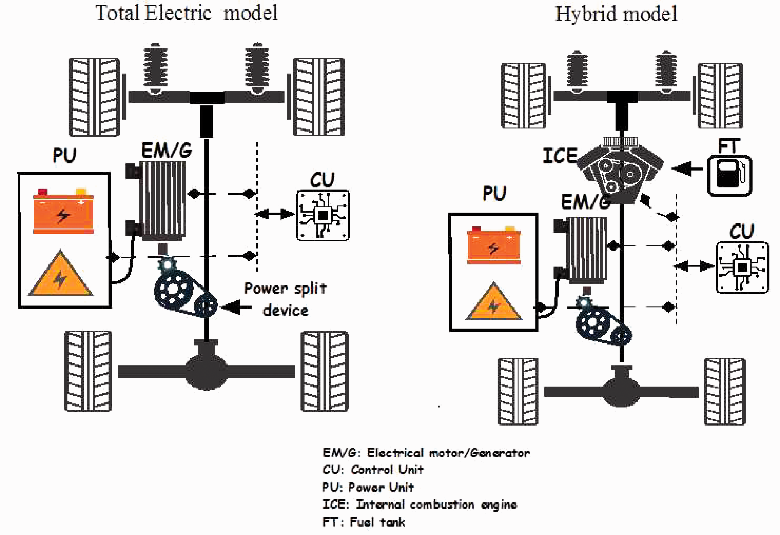
EV and HEV architectures.
Figure 1 illustrates the control unit which controls the overall power flow from the battery to the engine and other equipment. This unit can determine and estimate the power required for each case concerning real-time demand. The electric power required can be measured and calculated if the vehicle system model was designed and the corresponding mathematical equations are determined (Figure 3). 31 The next part provides and explains mathematical equations required to build a robust control phase for the next step of this study.
Mathematical equations
The mathematical equations required to simulate vehicle are based on various references, such as.30,32 These equations describe the vehicle electrical and mechanical models. All of the abbreviation used in this paper appears in the Nomenclatures list.
Mechanical part
The power and energy required for driving the vehicle are determined based on the concepts of the mechanics and aerodynamics automotive. (Figure 2). 33

Forces on a moving car.

Evolution of acceleration, speed and motor power for an electric vehicle.

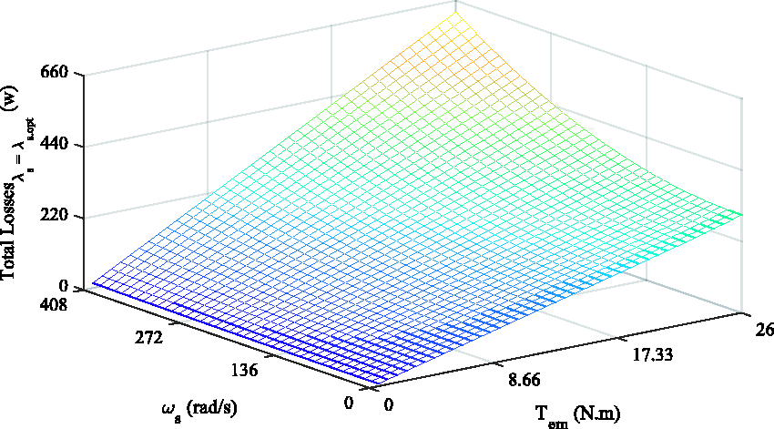
Total losses with nominal stator flux reference.
Optimal stator flux for the entire operation region.
The road load includes four forces component (Figure 2) which given by

The rolling resistance force F1 is accomplished through the flattening of the tire on the road surface is shown by

Where the speed of the vehicle, tire pressure, shape and surface characteristics of the road are nonlinearly dependent on μ. It increases with the speed and rotation of the vehicle. F1 can be reduced by holding the tires inflated as much as possible is indicated by

In general, this force is ignored based on rolling resistance. F3 (Aerodynamic drag force) is the viscous resistance of air that acts on the vehicle are given by
The resistance to climbing (F4 with positive operating sign) and downgrade (F4 with negative operating signs) are shown by

The electrical motor provides the tractive force in an electric vehicle to overcome the road load. The movement formula is determined by
The resultant force (F – Fr) accelerates the vehicle (or decelerates when Fr is more than F).
The power necessary for driving a vehicle must compensate for the road load Fr is given by

The mechanical equation used for each wheel drive (in the referral motor) is represented by

The next equation is calculated by the application of a reduction gear:
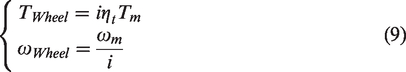
The load torque is specified in the reference motor by

The moment of global vehicle inertia in the reference motor is determined by

Electrical part
The electrical part will be limited only by the study of the electric power and the state of charge of the battery.


The authors demonstrated in
34
that the power consumed by the battery Pbatt is proportional to the speed of the electric vehicle Vv. The relationship between the two quantities is given by the equation below
35


Several methods are developed to express the SOC of the battery which is directly related to the energy stored by the battery and the mode of driving
Numerous research studies have shown that the acceleration ratio and the battery SOC status are inversed.30,36 The lithium battery model is given by equation (17).

Losses minimization algorithm
The proposed method is an algebraic approach based on steady-state IM modeling. We will consider that the induction machine is unsaturated. We will also consider steady-state conditions and neglect the converter losses. The machine parameters are considered constant regardless of the saturation level of the magnetic circuit.37,38 The objective of this approach is to formulate the stator flux reference in terms of the electromagnetic torque and the rotation speed.
Losses by joule effect in the stator
The stator winding can be connected as a star or delta. Since the motor is a balanced three-phase load.
39

In the star wilding connection, the resistance between two terminals R is connected to the resistance of each winding r by the relation:

The equation (18) can be written as

Iron loss
Iron loss is a function of the magnetic flux and dependent only on the supply voltage and the frequency of the stator currents. Since these quantities do not vary, iron loss may be considered constant regardless of the engine load. In practice, iron loss is measured by performing an unload test for the machine.

Loss by joule effect in the rotor
Joule loss of the rotor is a function of the power transmitted to it. We can also show that it is also a function of the resistance and the current flowing to the rotor as shown below:

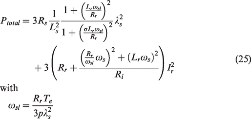
The total losses
Using the IM per phase equivalent circuit the stator current Is is given as follows:

Magnetizing current Im:

The expression of total losses:

Subsisting (20), (21), (22) and (23) into (24) gives:
Using the expression of
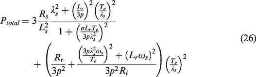
If we take into consideration that

Equation (27) can be written as:

Equation (28) can be simplified as:

With
Expression (29) is considered as the objective function of the proposed losses minimization algorithm. It is mainly related to the electric and magnetic machine parameters. In order to minimize this objective function, it is necessary to find the partial derivative related to the variable that we like to adjust. In our case, the reference stator flux magnitude will be taken as the adjust variable and it will be independently controlled; its value is calculated by the cancellation of the derived objective function. This is given as:

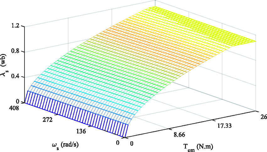
The optimal stator flux (Figure 5) is obtained by:

With:
The expression of the minimal losses for an optimal function is:

Figures 6 and 7 give the evolution of the total power losses onto a range of variation of the load torque and frequency going from 0% to 130% of their nominal value. Indeed, when the IM operates under the nominal load, the mechanism of minimization of losses brings nothing in terms of consumption economy (Figure 7). However, in low loads, the gained power is very evident by comparing both curves of losses obtained without and with the mechanism of minimization of the losses.
Total losses with optimal stator flux reference for the entire operation region.

The gained power.
Predictive torque control of the induction motor
The predictive torque control of the induction motor is based on the regulation of the load angle. It needs the estimation of the rotor and stator flux. In each sampling period, the torque controller estimates the load angle position

The aim of this strategy is based on the calculation of the stator reference flux vector

Flux vector positions.
The position

The stator resistance for the induction motor can be neglected when running at high speed.40,41 The required stator voltage vector will be given by the following expression:

Where
The stator and the rotor flux are given by the following relationship:

The relationship between the stator and the flux rotor can be determined by the expression (37):

It is supposed at the established regime, the stator flux turns with a constant magnitude

The combination of equations (38) and (37) gives:

Then the rotor flux becomes:


The electromagnetic torque is then expressed as:

The slip speed
In order to determine the PI parameters for the predictive torque control, many methods can be used in this paper Particle Swarm Optimization algorithm controller is carried out to tune parameters of PI.
Particle swarm optimization algorithm
Particle Swarm Optimization is an evolutionary algorithm that has been proposed by Eberhartend and Kenedy in 1995. 42 It was originally inspired by the world of life, specifically the social behavior of swarming animals, such as shoals of fish and group flights of birds. 43
We can observe in these animals relatively complex dynamics of displacement, whereas individually each individual has a limited “intelligence”, and only has local knowledge of his situation in the swarm. 44
The local information and the memory of each individual are used to decide on his movement. Simple rules, such as staying close to other individuals, going in the same direction, or going at the same speed, are enough to maintain the cohesion of the swarm and manage the complex and adaptive collective behaviors between them.
The swarm of particles corresponds to a population of simple agents, called particles. Each particle is considered a solution to the problem, where it has a position (the solution vector) and a velocity. In addition, each particle has a memory allowing it to remember its best performance (in position and value) and the best performance achieved by the “neighboring” (informative) particles: each particle has a group of informants, historically called its neighborhood.
At the start of the PSO algorithm, each particle is positioned (randomly or not) in the search space of the problem. Each iteration moves the particles according to three components:
current velocity of particle i at iteration k,vik the best position of particle i, p
best
the best position encountered by the particle and its neighbours g
best
The velocity and position of each particle are updated using equation (45) as demonstrated in
23
:

The Flowchart of the PSO algorithm can be illustrated as indicated in Figure 9.

Flowchart of the PSO algorithm.
This section covers the efficiency presentation of the proposed control algorithm. The used PSO configuration for tuning the PI parameters (Kp, Ki) of the torque controller is presented as follows:
Size of the swarm: n = 5 particles, Maximum number of birds steps or iteration: the optimized number is 50, The parameters c1 = 1.2 and c2 = 0.012, The inertia for each particle: w = 0.9, r1 and r2 are random parameters, The current positions xTe = [rand; rand]. Holding the best position pbest = xTe, Holding the global best position gbest = pbest, Evaluating the fitness cost through the Integral Square Error (ISE) method.
The objective of the PSO algorithm is to determine the two optimal controller parameters Kp and Ki such that the controlled system can reach the best step response output. The fitness cost function to be minimized is given by:
Where the electromagnet torque can be expressed in function of PI parameters and then it is possible to connect the PSO algorithm equation with the PI parameters. Equation (47), explains this relationship. f(k) indicates the torque equation system.

Figure 10, illustrates the inputs and the outputs of the PSO algorithm and describes the previous mathematical equation.

PSO tuning PI control parameters.
Where
At each cycle period, the PSO will compensate for the torque error by adjusting the PI parameters. Figure 11 shows the results related to the PSO part. During simulation running, the n particles search the global best position for the actual iteration. This means the minimum of the fitness cost function. The good position is transferred to other particles to adjust their position and velocity. Therefore, at the end of used iterations and the evaluation of the fitness cost, one can decide to maintain or to reload another number of iterations.
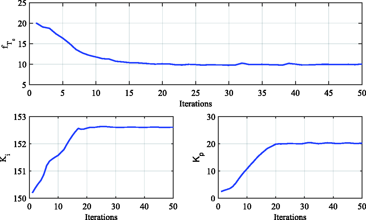
Evolution of the fitness cost and PI parameters.

Block diagram of an intelligent predictive torque control strategy with losses minimization.
The corresponding PI parameters (Ki and Kp) generated by the PSO algorithm are given in Figure 11. It is clear that the values of PI parameters are stabilized at the final number of iterations.
Results and discussion of predictive torque control drive with power losses optimization
To illustrate the behavior of predictive torque control drive with power losses optimization, the simulation programs are realized under the MATLAB/SIMULINK environment Figure 12. .
The simulations are carried out for a period of 100 µs and with a 4th order Rank-Kutta integration algorithm. This choice has a significant influence on the flux and torque ripples, and the switching frequency of the inverter switches.
The Ki and Kp parameters obtained by the PSO algorithm are compared to the Ziegler-Nichols (Z-N), Cohen-Coon (C-C) and Internal Model Control (IMC) tuning methods. Table 1, presents the obtained PI parameters.
Optimum tuning parameters of PI controller.

The performance of PI controller using these different tuning techniques and the sliding mode control are analyzed using MATLAB/Simulink platform. The reference flux is fixed at the nominal value λs* = 1.1 Wb. Ziegler-Nichols (Z-N), Cohen-Coon (C-C) Sliding Mode Control (SMC) and Internal Model Control (IMC) methods are compared to the optimization algorithm based on Particle Swarm Optimization (PSO) as shown in Figure 13.
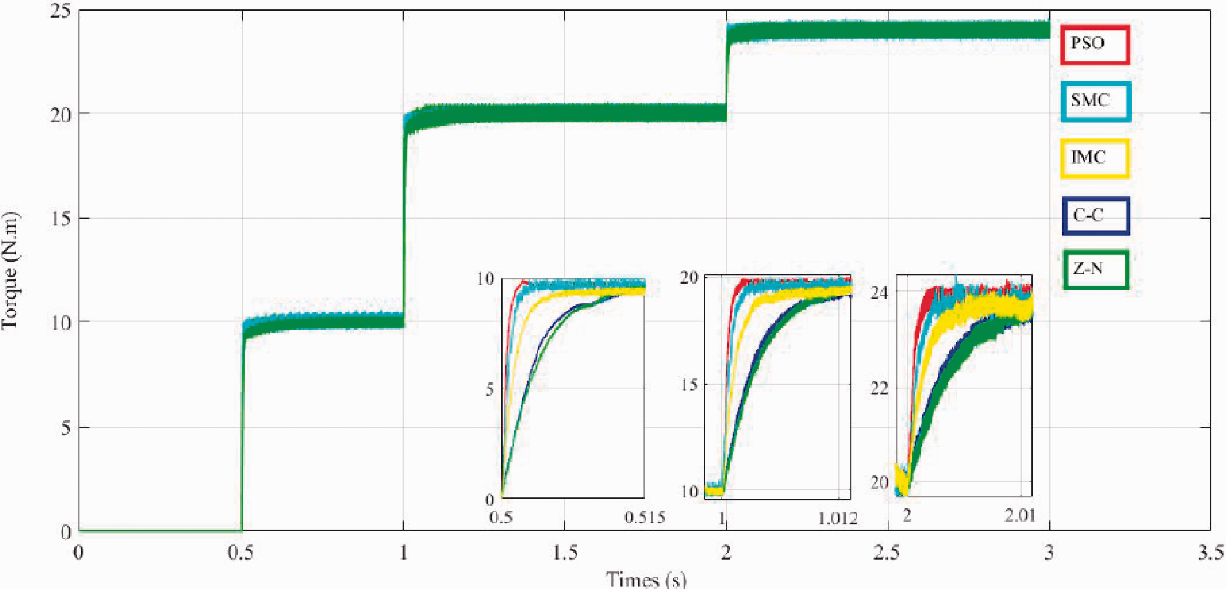
Operation with variable load torque using PSO, C-C, Z-N, SMC and IMC controller.
Very good tracking performances have been obtained with the designed PI controllers based on PSO. Figure 13 indicates that the designed PI_PSO have a fast rise time compared to that of the classical methods (Z-N) and (C-C). (IMC) and (SMC) have a good rise time almost similar to PSO technique. However, a major problem associated with SMC is the chattering phenomenon which is exhibited due to the high frequency and non-deterministic switching control signal. The disadvantage of IMC tuning method. It sets the controller’s integral time equal to system time constant. If the time constant of the controlled system is very long, consequently, the controller will have a very long integral time. Long integral times make recovery from system disturbances very slow.
The good torque and flux responses are verified. It can be seen that torque oscillations are very low compared to the response on the classic DTC. The obtained results are promising and show the effectiveness of the PSO algorithm.
Figures 14 to 16 illustrate the simulation results of the stator flux the electromagnetic torque, the rotor speed, and the stator. These results show good dynamics for speed and torque. Using the power losses optimization algorithm it can clearly be observed that the magnitude of stator flux is variable with the function of the load torque. The stator current follows the increase of electromagnetic torque with a quasi-sinusoidal ac waveform.

Magnitude of stator flux with losses minimization. The evolution of stator flux.

Electromagnetic torque and rotor speed.

Stator currents.
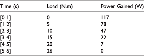
The gained power obtained by the loss minimization algorithm is shown in Figures 17 and 18. Table 2 summarizes the efficacy of this optimization method in terms of power gain. It is clear that this algorithm of minimization losses ensures a significant power when working at a light load. When the load torque is increased, the optimization algorithm has a little benefit as the power gain decays.

Losses with and without flux optimization.

The power gained by flux optimization.
The power gained by flux optimization with the function of torque load.
Conclusion
In this paper, an energy optimization algorithm for an electric car based on losses minimization and intelligent predictive torque control is designed. The loss minimization algorithm is based on the optimization of the stator flux for the induction motor. The simulation results show the efficacy of this method in terms of energy gain, especially at light load torque. The application of the predictive control of the electromagnetic torque based on PSO technique to tune the controller parameters allows the reduction of torque ripple and improve its response time. A comparative study with other tuning methods for the torque controller proves the efficacy of the designed PI controllers based on PSO.
Declaration of Conflicting Interests
The author(s) declared no potential conflicts of interest with respect to the research, authorship, and/or publication of this article.
Funding
The author(s) disclosed receipt of the following financial support for the research, authorship, and/or publication of this article: The authors gratefully acknowledge the approval and the support of this research study by the grant No. ENG-2017-1-8-F-7440 from the Deanship of Scientific Research at Northern Border University, Arar, KSA.