
Abstract
The quality of torque of induction motors plays an important role in many electrical drive systems. Model predictive torque control has been a good alternative to conventional direct torque control for improving the torque qualities. Recently, some researchers tried to modify the model predictive torque control with other principles such as minimize torque ripple, optimize duty cycle, in an effort to get smaller torque ripples. However, according to the reported results the torque ripples are still significant. In this article, model predictive torque control based on particle swarm optimization is proposed to modify the model predictive torque control in order to improve the control qualities, especially the steady-state torque ripples. The key idea of this approach is using particle swarm optimization to minimize the cost function. The optimal voltage vector is implemented by space vector modulation technique. In addition, the control performance of model predictive torque control–particle swarm optimization combination is also compared with that of model predictive torque control–genetic algorithm to justify the effectiveness of our method. The presented simulations prove the better torque and phase currents quality at steady state of this approach.
Keywords
Introduction
Among all types of alternating current (AC) machines, induction motors (IMs), especially the cage types, are mostly used in industry. 1 The magnitude and frequency of the electrical source module, the inverters, are adjusted to control the IMs. For various types of inverters, voltage source inverter (VSI) is popularly employed in industry. In many applications, the precise torque response is required. Direct torque control (DTC) is widely used control strategy for such applications.2–4 DTC strategy chooses among the available voltage vectors of the inverter to adjust the torque of the motor without requiring any current regulator or coordinate transformation. The advantages of DTC are fast torque response and easy implementation. However, the large amount of torque ripple and current swing in case of small load are the main disadvantages.2,5 Recently, model predictive torque control (MPTC) has been introduced as an alternative to conventional DTC for overcoming such weaknesses.6–10
MPTC uses the set of available voltage vectors of VSI to minimize the predicted torque error and stator flux error. The accurate model with minimization principle makes MPTC better than conventional DTC. 8 The applications of MPTC have been researched widely in a lot of studies.6,8,9,11 However, applying only one voltage vector during the whole control period is not optimal in terms of reducing the torque ripple.12,13 Davari et al. 12 decreased the amount of torque ripple by calculating the optimal weighting factor, and the control period is divided into two intervals. Besides, Yongchang Zhang and Yang 13 proposed MPTC with optimal duty cycle control and implemented the active voltage vector along with zero vector in one control period. The better torque performance was claimed in both Davari et al. 12 and Zhang and Yang. 13
In an effort to get even smaller torque ripple at steady state, this article has proposed to use particle swarm optimization (PSO) in combination with MPTC. PSO is employed to get the exact solutions for minimizing the cost function. The space vector modulation (SVM) technique is implemented to produce the required optimal voltage vector. The proposed method is partially compared with the improved MPTC in Zhang and Yang 13 and the MPTC-genetic algorithm (GA) combination about torque ripple criteria. The simulation results show that the proposed approach has a better performance at steady state.
IM modeling
The electromagnetic relationships inside IMs are represented through an equivalent circuit as shown in Figure 1, where


Equivalent circuit of induction motor.
From equation (4), we have equation (5)

Replacing equation (5) into equations (1) and (2), we get equations (6) and (7)


Derivating two sides of equation (7), we obtain equation (8)

Also

In equivalent

Employing the following annotations

The final model is obtained as equations (12) and (13)


Electromagnetic torque

where p is the number of pole pairs. Moreover, the motion equations of motor are as follows


where
VSI with SVM
In this article, three-phase two-level VSI depicted in Figure 2 is introduced. Each phase has two insulated-gate bipolar transistors (IGBTs). Each IGBT operates only in two states: ON (1: conduct current) and OFF (0: no current). Two IGBTs in the same phase are never in the same state. In Table 1, there are eight values of output with three phases, for VSI.

VSI circuit principle.
Description of eight operating states of VSI.

VSI: voltage source inverter.
Because of

As a result, the VSI has eight values of

Available voltage vectors of VSI.
So far, there are many modulation techniques, which can precisely generate the voltage vector with module and phase as demanded from the available voltage vectors. One of these efficient modulation techniques is called SVM. The principle of SVM is shown in Figure 4.
15
Suppose that the input voltage


SVM principle.
If


The sequence of calculation remains the same if the vector
Particle swarm optimization
Similar to other population-based optimization method such as GA, PSO is among the most popular evolutionary-type optimization algorithm used nowadays.16–22 First proposed by Kenedy and Eberthart, PSO mimics the movement of individuals (fishes, birds) within a group (school, flock). Suppose that a group of P individuals are searching for foods inside a search space. The individual movements rely on their own experiences and the position of the individual which is nearest from the foods. Each individual has its own position

Proposed MPTC-PSO design
The proposed MPTC-PSO control structure is depicted in Figure 5. It includes two control loops: the inner loop for predictive torque and flux control and the outer loop for speed control, respectively.

Proposed MPTC-PSO structure.
Speed control
Based on the motion equation (15), we have transfer function from torque to speed as follows

The proportional–integral (PI) controller is employed to control motor speed. The outer control loop must respond slower than the inner control loop to guarantee the quality of cascade control structure. Here, the sampling time of outer control loop is
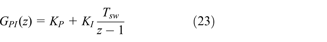
The values
Predictive torque and flux control
With small sampling time, we can use first-order Euler approximation


The stator flux


Denote

in which

Next, we will consider the constraints when minimizing the cost function. Considering the operating conditions of the IM, phase currents are the important parameters. For safety reasons, we limit the phase currents inside a permitted range. This range allows motor generate enough torque when starting, also allow motor working overload for a short period without any damage. Normally, the range of the phase currents is

The implementation steps of the proposed MPTC-PSO.
Simulation results and discussions
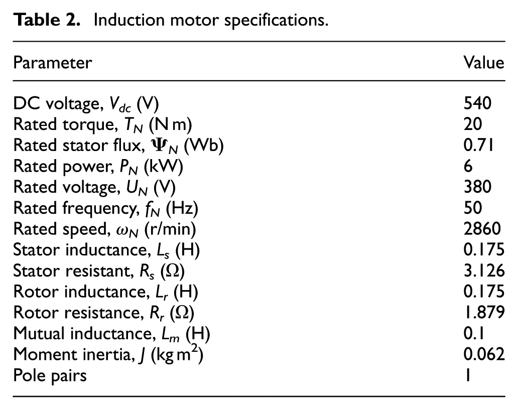
The simulation diagram with MATLAB/SIMULINK is shown in Figure 7. The parameters of IMs, PSO algorithm and GA algorithm are given in Tables 2–4, respectively.

Simulation diagram.
Induction motor specifications.
Parameters of PSO.

PSO: particle swarm optimization.
Parameters of GA.

GA: genetic algorithm.
In this simulation, the magnitude of phase currents is smaller than 65 A. Three typical operating circumstances of IM are demonstrated as follows.
No-load starting
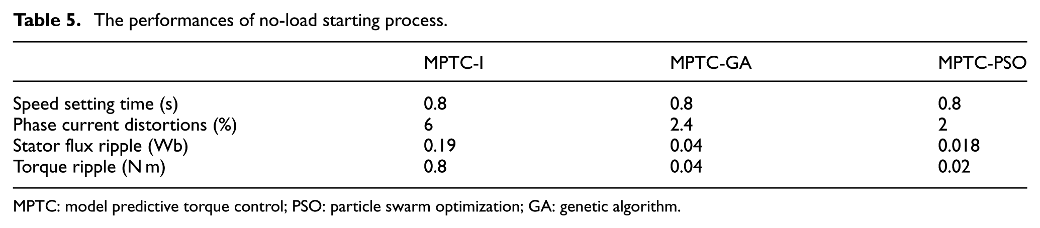
The no-load starting process of the three designed CSs from zero to rated speed is shown in Figure 8. Due to being regulated by the same speed controllers, the speed responses nearly overlay each other as seen in Figure 8(a). All the speed responses have no overshoot with the small settling time. A small difference between them still exists because of the differences in torque response. Figure 8(b) describes the transient process of phase currents. It is clear that the phase currents are kept in safe range [−65 A, 65 A] during the starting process. The magnified view shows that the phase current distortions of MPTC-I are biggest with 6%. It is followed by MPTC-GA with 2.4% of current distortions. The MPTC-PSO presents only 2% of current distortions. The stator flux quickly reaches the reference value of 0.71 Wb as shown in Figure 8(c). The magnified view of flux responses reveals the largest flux variations of MPTC-I and the smallest flux ripple of MPTC-PSO. The torque responses of all CSs are plotted in Figure 8(d). If the speed is still smaller than the reference value, the maximal value of torque is generated, which leads to the highest value of acceleration. The amount of torque ripple is 0.8, 0.04, and 0.02 N m for MPTC-I, MPTC-GA, and MPTC-PSO, respectively. Because of finding out the most optimal solution, MPTC-PSO provides the better speed response, better phase current response, better flux response, and better torque response, than those of both MPTC-I and MPTC-GA. The detailed control qualities of three designs are presented in Table 5.
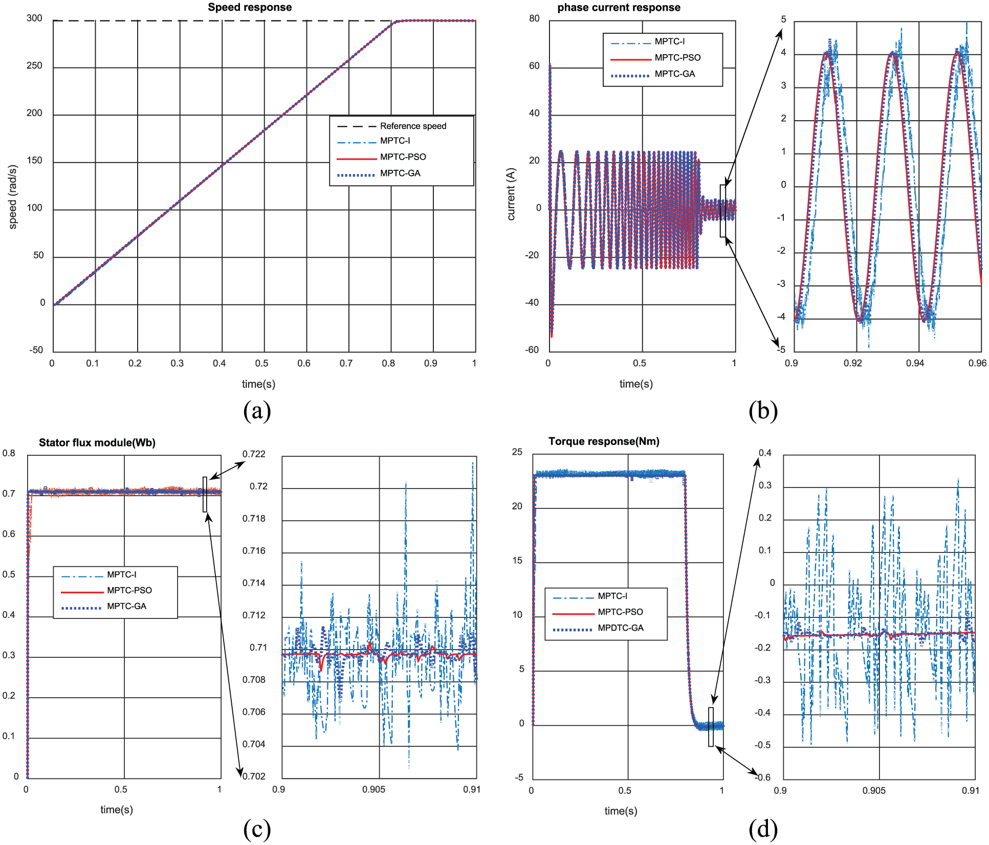
The responses of control systems in no-load starting process: (a) speed, (b) phase current, (c) stator flux, and (d) torque.
The performances of no-load starting process.
MPTC: model predictive torque control; PSO: particle swarm optimization; GA: genetic algorithm.
Load disturbance
Figure 9 shows the responses with load variation of the three CSs. A 50% rated load is applied at 0.2 s. The speed reference value is kept at rated value. For all the CSs, the effect of load disturbance on speed is completely handled after 0.6 s. The phase currents vary within the legal range while its steady-state distortion is 2.1%, 0.8% and 0.64% in MPTC-I, MPTC-GA and MPTC-PSO, respectively. The load disturbance has no significant effect on the stator flux, whose values are nearly the same throughout. As same as the previous case, the biggest amount of flux ripple is presented in MPTC-I, while the smallest one is observed in MPTC-PSO. The torque ripple is 0.65, 0.3, and 0.03 N m for MPTC-I, MPTC-GA, and MPTC-PSO, respectively. The summary of control performances of the three control designs is described in Table 6.
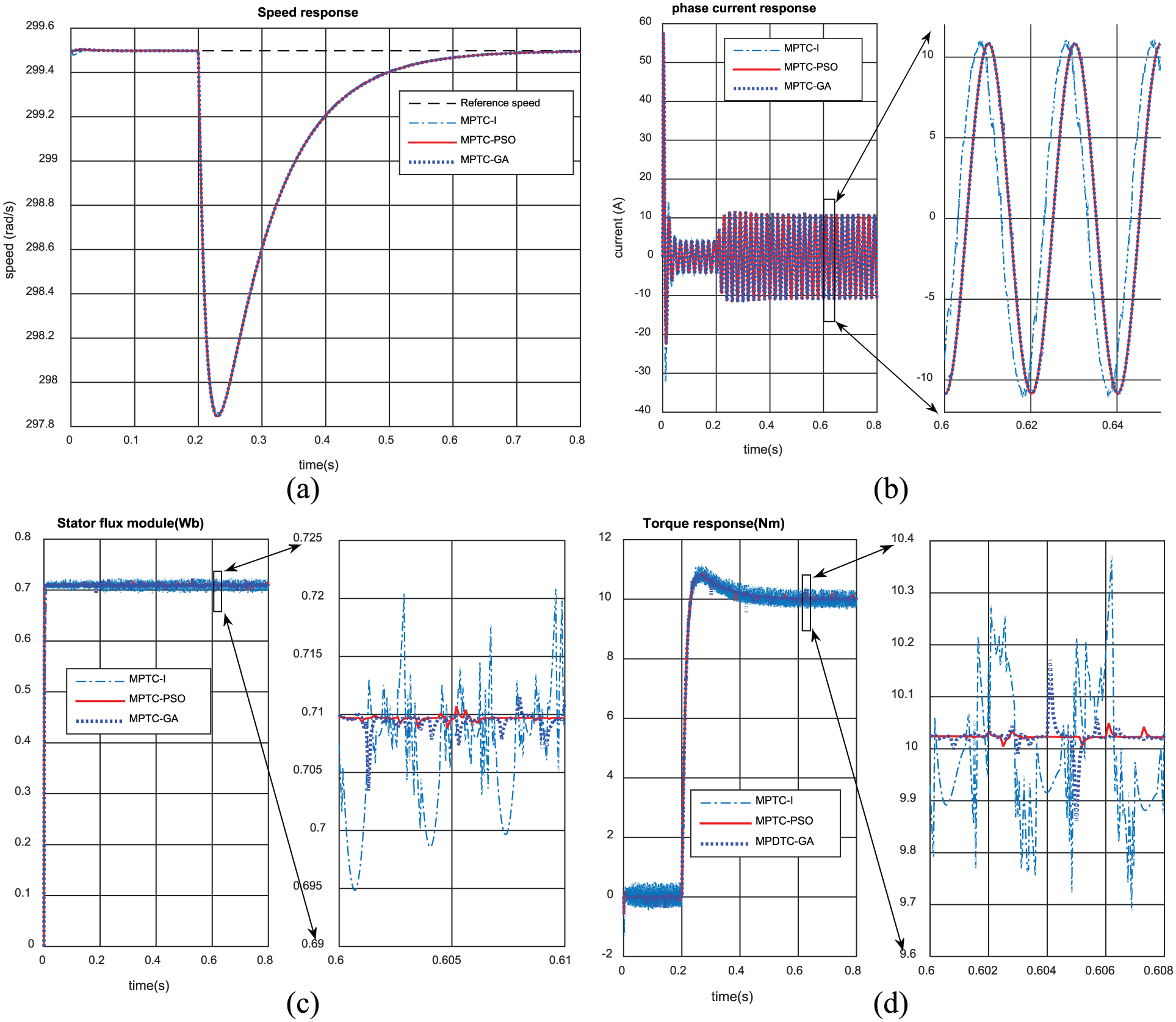
The responses of control systems when 50% rate load applied to motor at 0.2 s: (a) speed, (b) phase current, (c) stator flux, and (d) torque.
The control performances of load disturbance process.
MPTC: model predictive torque control; PSO: particle swarm optimization; GA: genetic algorithm.
Reversing
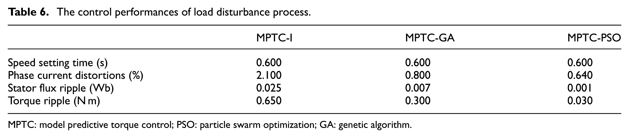
Figure 10 represents the reversed process of three control designs. The speed changes smoothly without overshoot from 50% rated value to −50% rated value in about 0.8 s. The phase current values vary within the safe range. Similarly, at the steady state, the current distortion amount is 6.2%, 3.1%, and 2.2% for MPTC-I, MPTC-GA, and MPTC-PSO, respectively. The stator flux remained unchanged throughout the reversed process. The amount of torque ripple is 0.6, 0.04, and 0.02 N m for MPTC-I, MPTC-GA, and MPTC-PSO, respectively. The qualities of MPTC-PSO are clearly better than the other two approaches. The system qualities in reversing process are listed in Table 7.
The responses of control systems when reversing the reference speed at 0.2 s: (a) speed, (b) phase current, (c) stator flux, and (d) torque.
The control performances of reversing process.

MPTC: model predictive torque control; PSO: particle swarm optimization; GA: genetic algorithm.
Low-speed operation
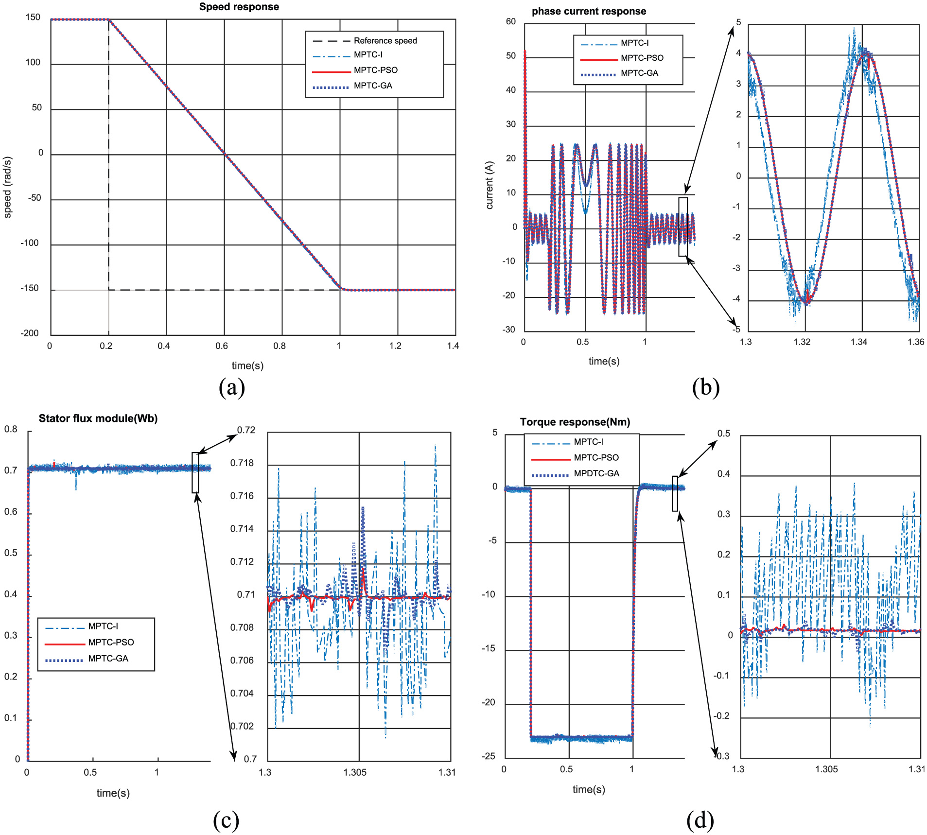
Figure 11 shows the starting process and load disturbance rejection of the three CSs at low-speed operation. In Figure 11(a), an IM starts from zero to reference speed (10% of the rated speed) before withstanding the load disturbance at 0.3 s. The three speed responses are close to each other that the same as the above results. The phase current is limited within the safe range; the current distortion of all three current responses is very small. The main differences between the three CSs are observed from the stator flux (Figure 11(c)) and torque responses (Figure 11(d)). The steady-state stator flux ripple of MPTC-I, MPTC-GA, and MPTC-PSO is 0.004, 0.003, and 0.001 Wb, respectively. The torque ripple values are slightly different between low-load condition and full-load condition as indicated in Table 8. In all cases, the MPTC-PSO demonstrates the better performances over the other two control designs.
The responses of control systems in low-speed operation: (a) speed, (b) phase current, (c) stator flux, and (d) torque.
The control performances in low-speed operation.

MPTC: model predictive torque control; PSO: particle swarm optimization; GA: genetic algorithm.
Because of the memorial ability of PSO, all particles retain the knowledge of good solutions. In contrast, the previous experiences are not considered after each evolution of GA. Therefore, PSO has perfect memory capability than GA. 23 Also, PSO is very effective in keeping the diversity of the swarm, since all particles use the information related to the most successful particle to improve them, whereas in GA the worse solutions are rejected and only the good ones are maintained. Thus, in GA, the population only includes a part of the best individuals. In addition, low computation cost and quickly convergence ability make PSO popular in many applications.
Finally, the converged performances of PSO are shown in Figure 12. In each sampling time, PSO rapidly reaches the final result, which is shown in Figure 12(a). During the simulation, the cost function value quickly decreases to 0 and remains at that value until the end of the simulation (Figure 12(b)). As a result, the stability of the proposed control approach is guaranteed.

The performances of PSO: (a) the typical convergence in one sample time and (b) the typical convergence of cost function during simulation process.
Conclusion
MPTC-PSO method has been employed to control the IM fed by VSI. The PSO algorithm has been used to get the exact optimal voltage vector to minimize the objective function. The designed CS inherits the fast torque and flux response of DTC principle. In addition, the use of PSO algorithm to solve the optimization problem led to better performances at steady state. Moreover, the proposed control structure can effectively handle the stator phase currents in the safe range to protect motor while enhanced the control quality in all of the motor operations. A comparative study with the MPTC-GA and one published MPTC method has been carried out. The simulation results show that steady-state phase current has smaller distortions, and the amount of torque and flux ripple is significantly reduced. In the future, MPTC-PSO may be utilized to control other AC machines, power electronic converters, electrical systems, and so on.
Footnotes
Academic Editor: Stephen D Prior
Declaration of conflicting interests
The author(s) declared no potential conflicts of interest with respect to the research, authorship, and/or publication of this article.
Funding
The author(s) disclosed receipt of the following financial support for the research, authorship, and/or publication of this article: This paper is supported financially in part under MOST No. 104-2221-E-151-015-MY2, Ministry of Science and Technology, ROC.