
Abstract
The accuracy of computer-aided design/computer-aided manufacturing (CAD/CAM) methods plays an important role in the clinical success of ceramic veneers. This study aimed to evaluate the impact of different CAD/CAM methods, including subtractive, hybrid, and additive manufacturing, on the trueness and precision of ceramic veneers. A typodont central incisor was prepared for a laminate veneer, followed by the design of a veneer with CAD software. Ceramic veneers were fabricated with four different CAD/CAM methods, including milled lithium disilicate, pressed lithium disilicate with three-dimensional (3D) printed wax patterns, milled zirconia, and 3D-printed zirconia. All veneers were scanned and imported to 3D inspection software for trueness and precision evaluation. Laminate veneers fabricated with all investigated methods exhibited clinically acceptable trueness and precision. Pressed lithium disilicate veneers from 3D-printed wax patterns and 3D-printed zirconia veneers showed lower precision of the fitting surfaces compared to their milled counterparts.
Introduction
Ceramic laminate veneers are aesthetic dental prostheses that effectively restore teeth with minimal invasiveness, providing long-lasting results.1,2 Classically, laminate veneers are made from feldspathic porcelain on refractory dies or platinum foils with the disadvantages of technique sensitivity and inability to modify the veneers after try-in.3,4 More recently, laminate veneers have been fabricated by heat-pressing after an investment of manually made wax patterns with the introduction of pressable lithium disilicate ceramics.5,6 The high-glass content ceramics are generally the material of choice to make laminate veneers due to their translucency and etchability for adhesive purposes. 7
Digital dentistry has changed the manufacturing process of ceramic restorations, including laminate veneers. 8 At present, computer-aided design and computer-aided manufacturing (CAD/CAM) techniques to fabricate laminate veneers include milling from glassy ceramic blocks 9 or heat-pressing using pressable glassy ceramic ingots after investing CAD/CAM milled or printed wax patterns.10,11 Recently, high-crystalline content ceramics such as zirconia have been increasingly used to make laminate veneers because of their high strength, 12 ability to mask dark tooth substrate, improved translucency due to a higher percentage of yttria, 13 and improved bonding properties thanks to new surface treatment methods.14,15
Zirconia CAD/CAM restorations are traditionally fabricated by milling methods or subtractive manufacturing. Recently, three-dimensional (3D) printing or additive manufacturing of zirconia restorations has been introduced and compared with traditional milling methods. 16 The comparative approaches to the accuracy of the ceramic restorations include evaluating the trueness and precision digitally or measuring the marginal gaps with the silicone replica method.17,18 Although recent studies explore the accuracy of CAD/CAM methods for full-coverage crowns, research specifically evaluating their trueness and precision for laminate veneer fabrication remains limited.19–21
The objectives of this study were to evaluate the trueness and precision of ceramic laminate veneers fabricated with CAD/CAM milled lithium disilicate, pressed lithium disilicate with 3D-printed wax patterns, CAD/CAM milled zirconia, and 3D-printed zirconia. The null hypothesis proposed that the CAD/CAM methods would not affect the trueness, precision, and actual accuracy of laminate veneers.
Materials and methods
Veneer design and fabrication
The flowchart of the research protocol is illustrated in Figure 1. A maxillary arch typodont (Foshan Jingle, Guangdong, China) was used to prepare the maxillary central right incisor veneer. Before preparation, the typodont was scanned by an intraoral scanner (i700, Medit, Gyeonggi-do, Korea) to serve as a reference for designing the veneer. The preparation was done with 0.7 mm of labial reduction, 1.0 mm of proximal reduction, 1.5 mm of incisal reduction with butt joint type, and a supragingival chamfer finish line. The abutment was polished by a silicone polisher (OneGloss, Shofu, Tokyo, Japan). Next, the typodont was rescanned with the same scanner followed by the fabrication of a 3D-printed metal study die. Both preoperative and postoperative scans were imported to CAD software (Exocad, Darmstadt, Germany) and a veneer was designed by copying the original preoperative shape and exported as a standard triangular language (STL) file. The cement gap was set at 50 µm for the intaglio area by a distance of more than 1 mm from the margin.
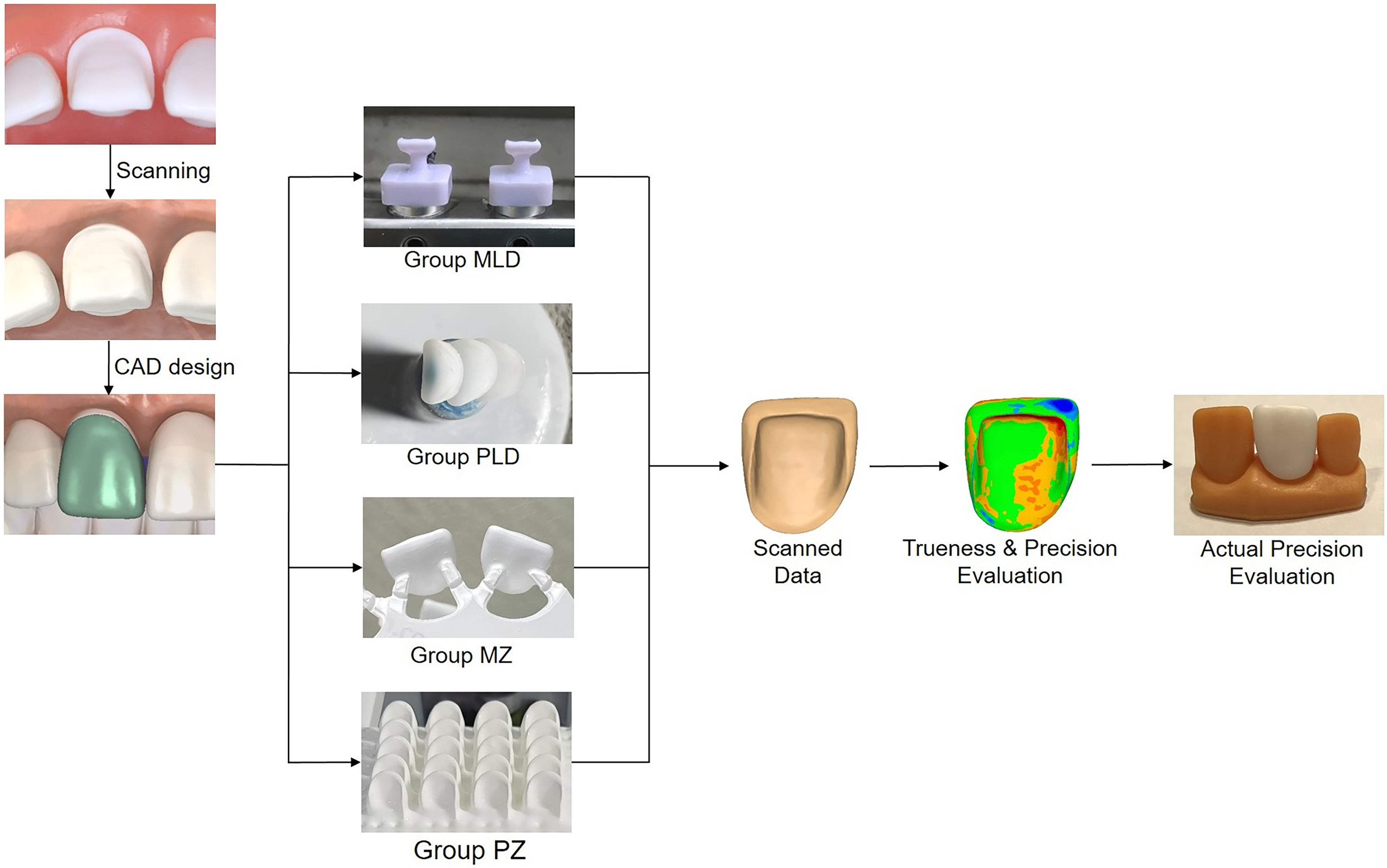
Flowchart of research protocol.
Based on the STL file, 40 laminate veneers were fabricated according to four different CAD/CAM methods (n = 10). In the first group, the veneers were CAD/CAM milled from 10 lithium disilicate (MLD) blocks (Cameo Glass Ceramics, Aidite, Hebei, China) with a milling machine (Coritec 350i, Imes-Icore, Ilmenau, Germany) in wet milling mode. In the second group, wax patterns were printed with a high-resolution 3D printer (Photon D2, Anycubic, Shenzhen, China) and a castable resin (Dental Castable, Anycubic, Shenzhen, China) and veneers were heat-pressed using a furnace (Programat EP3010 G2, Ivoclar, Liechtenstein) from lithium disilicate (PLD) ingots (IPS e.max Press, Ivoclar, Liechtenstein). In the third group, veneers were CAD/CAM milled from a zirconia (MZ) disc (Superfect Zir, Aidite, Heibei, China) with the same milling machine in dry milling mode. In the final group, veneers were printed with a zirconia (PZ) 3D printer (ZIPRO Dental, AON, Gyeonggi-do, Korea) and a zirconia slurry (INNICERA, AON, Gyeonggi-do, Korea). The build angle during printing in both PLD and PZ groups was set at 180° to achieve high accuracy and minimise the number of required supports which were only placed at the incisal area, and the z-axis resolution was set at 30 µm.22,23 Milling and pressing supports were placed at the cervical third and the centre of the labial surface of the veneers, respectively.
Trueness and precision evaluation
After sintered according to the manufacturer's recommendations, the veneers were scanned with the same intraoral scanner and exported as STL files. The STL files were imported to a 3D mesh editing software (Meshmixer, Autodesk, San Rafael, CA, USA) to remove the scanning support and separate each file into three parts including marginal, internal, and external surfaces, and exported as STL files. The boundary between the marginal area and intaglio surface was the line at a distance of 1 mm from the margin line. Next, the STL files of all parts and the entire veneers were imported to a 3D-inspection software (Medit Design, Medit, Gyeonggi-do, Korea) for evaluation.
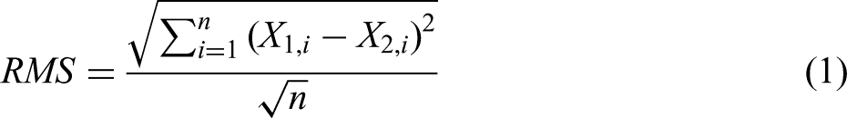
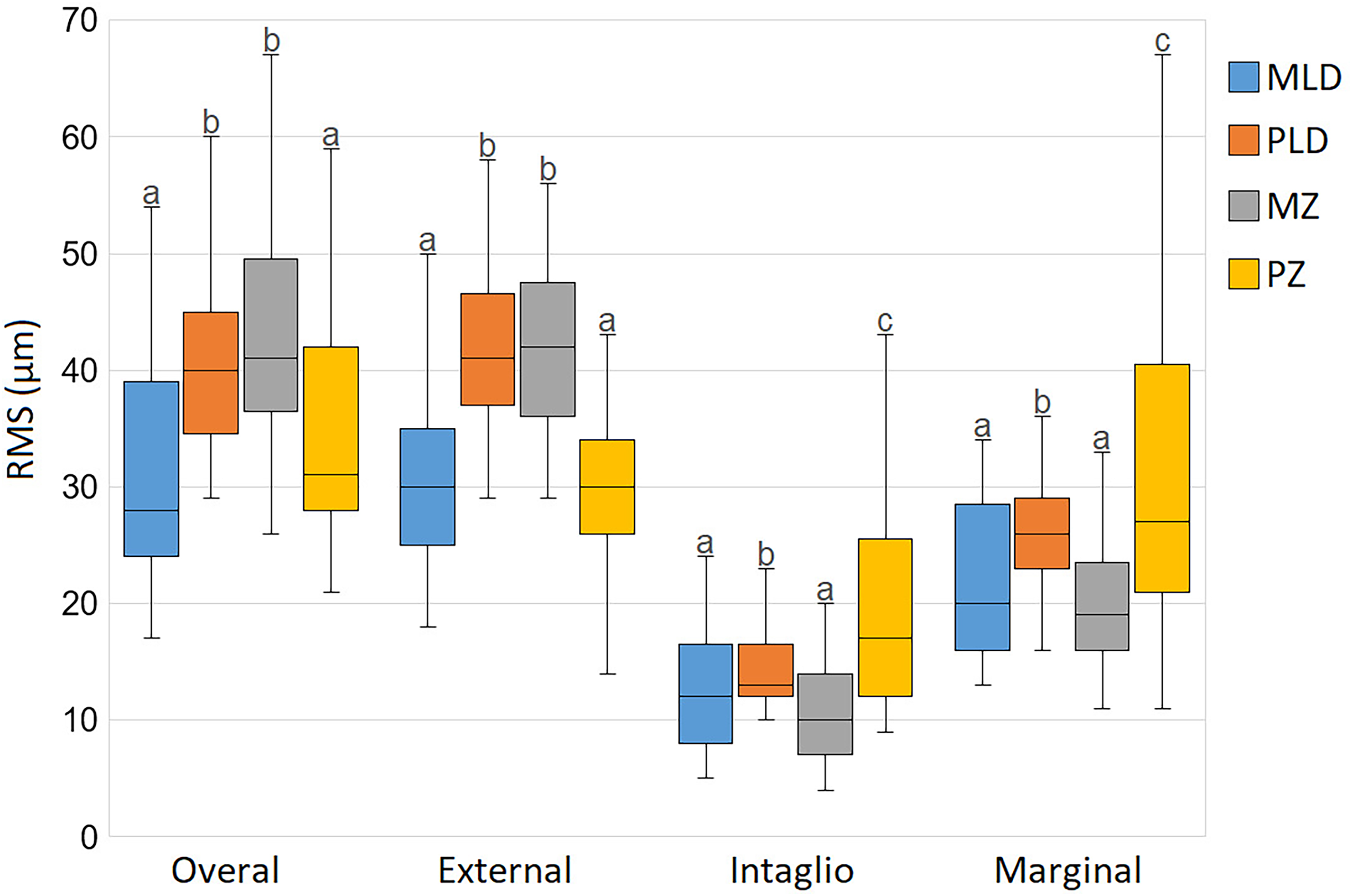
For evaluating the trueness, the CAD design was set as a reference, while the entire scanned veneers and their parts were targets. The superimposition was performed between the fitting surface of each fabricated veneer, which was a combination of the marginal and intaglio surfaces, and the reference with best-fit alignment. The colour maps were generated to represent the 3D deviation with a range from −100 μm (blue) to +100 μm (red) and a tolerance range of ±20 μm. The root mean square (RMS) value was calculated for the entire veneers and their parts by applying the following formula:19,23

Statistical analysis
To control for scanning and measurement reliability, two observers performed the scanning and measurements of trueness, precision, and actual precision. Inter-observer reliability was analysed with the intraclass correlation coefficient (ICC). All data analyses were performed with a statistical software package (IBM SPSS Statistics v23.0, IBM Corp, Armonk, NY, USA). First, the normal distribution of the data was confirmed with the Shapiro–Wilk test. Next, the differences in RMS values among CAD/CAM methods were analysed with the one-way analysis of variance (ANOVA) and Tukey test (α = 0.05).
Results
The inter-observer reliability was excellent with an ICC of 0.933 for trueness and precision measurement and an ICC of 0.945 for actual precision evaluation indicating high reliability of the scanning, aligning, and measuring procedures. There were statistically significant differences in both trueness and precision among groups (p < 0.001) except for the trueness of the marginal area. On trueness evaluation, the PLD group exhibited the lowest overall trueness. Both zirconia groups showed higher external surface trueness compared to lithium disilicate groups (Figure 2). The trueness of the intaglio surface was highest in the MLD group, followed by the MZ, PZ, and PLD groups. The MZ and PZ groups exhibited comparable trueness of all surfaces.
Box-plot comparing the trueness of overall, external surface, intaglio surface, and marginal area of laminate veneers fabricated with different CAD/CAM methods. The RMS values of groups with the same lowercase letter (a, b, or c) were not statistically different, as determined by the post-hoc Turkey test at α = 0.05.
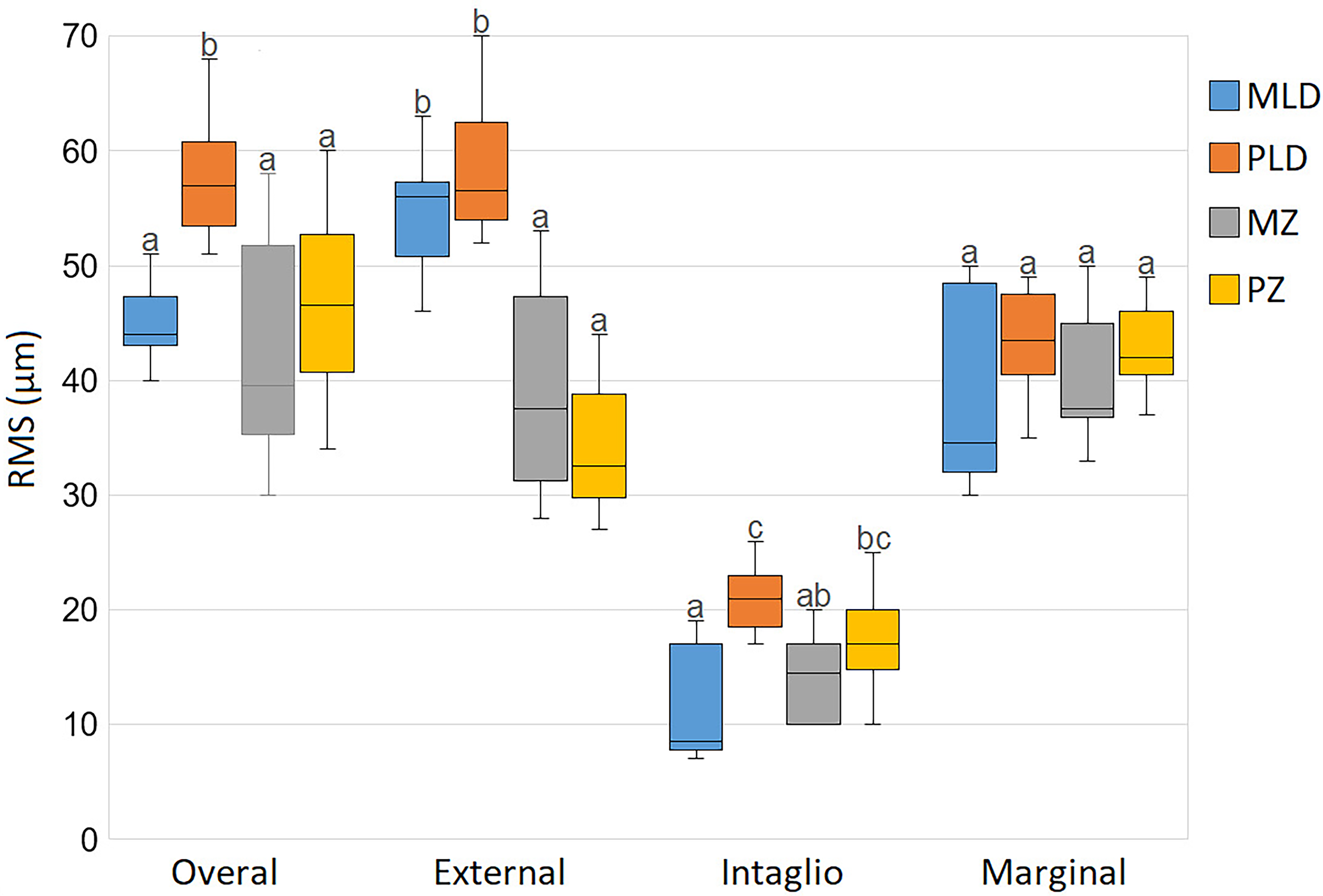
On precision evaluation of the overall and external surface, the MLD and PZ groups had higher precision than the remaining groups (Figure 3). The precision of marginal and intaglio surfaces was highest in the MLD and MZ groups, followed by the PLD group, and lastly the PZ group. In all groups, the intaglio surface showed higher trueness and precision than the other areas. There was no statistically significant difference in the trueness and precision of the fitting surfaces between MZ and PLD groups.
Box-plot comparing the precision of overall, external surface, intaglio surface, and marginal area of laminate veneers fabricated with different CAD/CAM methods. The RMS values of groups with the same lowercase letter (a, b, or c) were not statistically different, as determined by the post-hoc Turkey test at α = 0.05.
The generated colour deviation maps are presented in Figures 4 and 5. The areas on the external surface where printing or scanning supports were placed showed the lowest trueness and precision and were illustrated by red colour representing positive errors. Additionally, the marginal line area showed negative errors represented by blue colour. On the assessment of actual precision by two prosthodontists, high scores were recorded with no statistically significant differences among groups (Table 1).
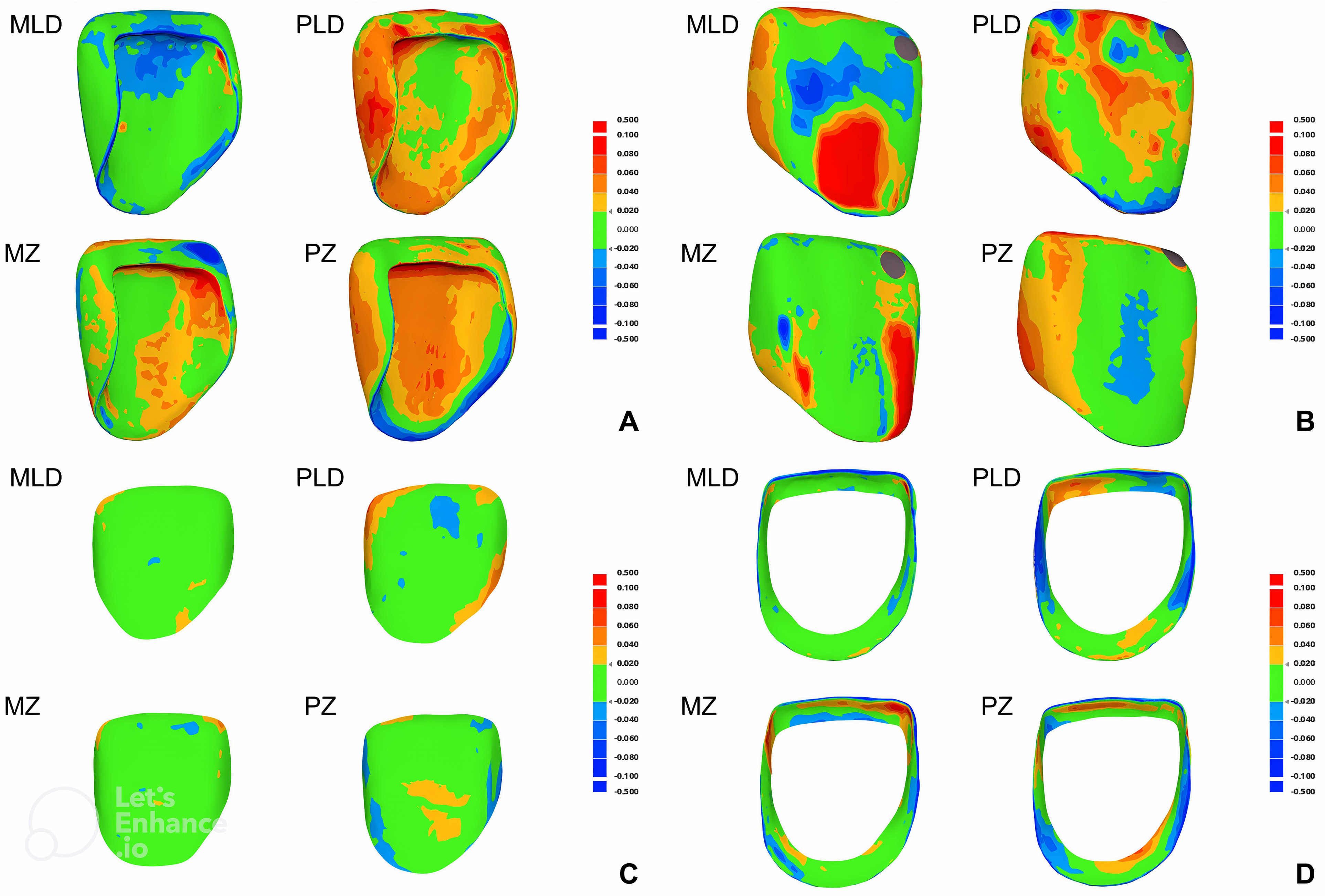
Visual deviation analysis of trueness by using colour maps. Green indicates good trueness, red and yellow represent positive error, and blue indicates negative error.
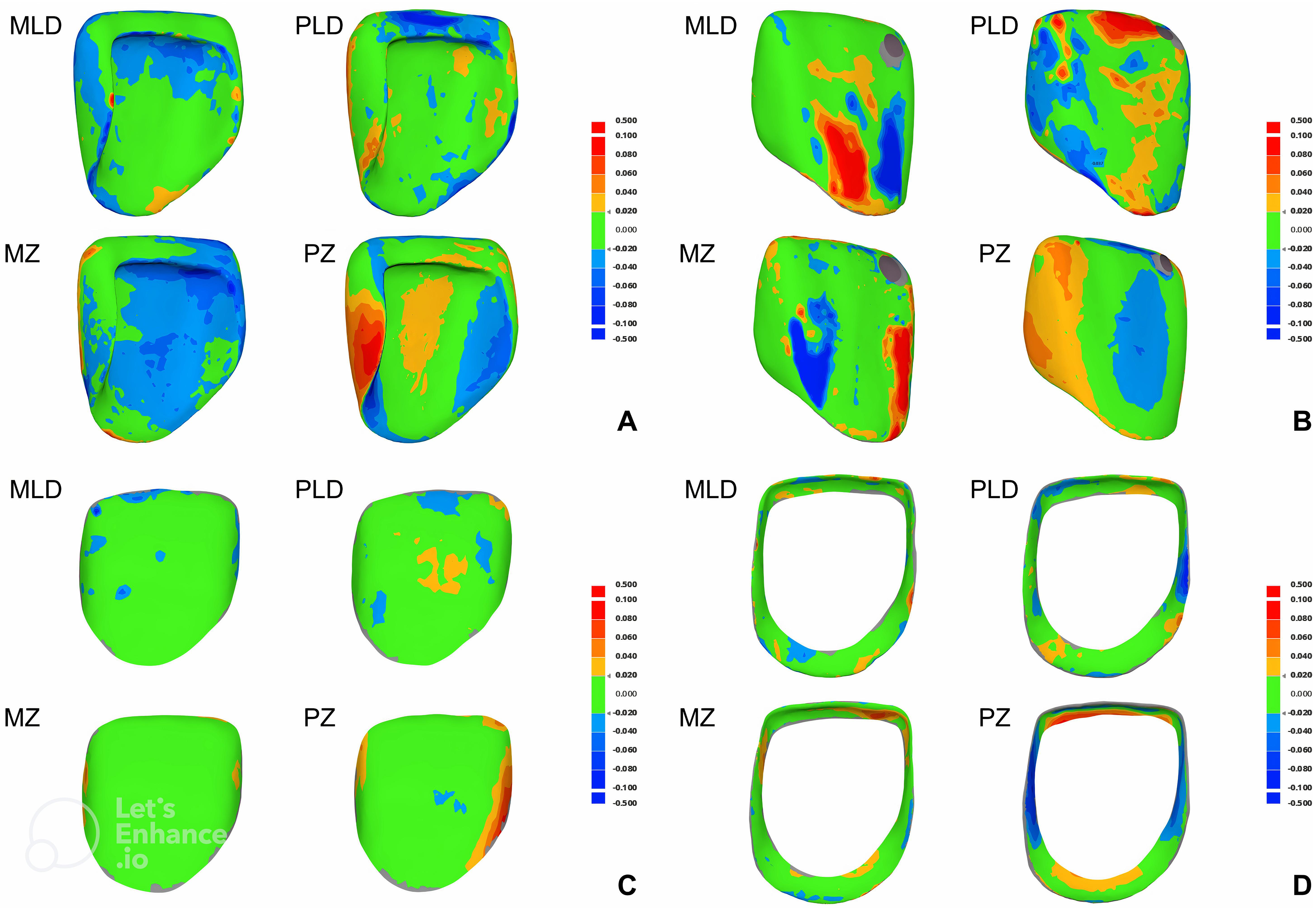
Visual deviation analysis of precision by using colour maps. Green indicates good precision, red and yellow represent positive error, and blue indicates negative error.
Assessment of the actual precision of the veneers by experienced prosthodontists.
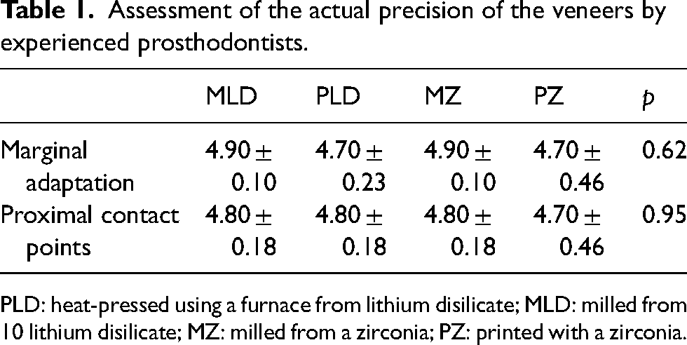
PLD: heat-pressed using a furnace from lithium disilicate; MLD: milled from 10 lithium disilicate; MZ: milled from a zirconia; PZ: printed with a zirconia.
Discussion
This study was conducted to examine the trueness and precision of ceramic veneers manufactured by different CAD/CAM methods. Based on the results, it was proven that the CAD/CAM methods had a significant effect on the trueness and precision of the ceramic veneers. Hence, the research null hypothesis was rejected.
In this in vitro study, the accuracy of four veneer CAD/CAM fabrication methods was evaluated. While lithium disilicate milling and pressing, and zirconia milling are well-established clinical techniques, the inclusion of zirconia 3D printing represents a novel approach with the potential to improve efficiency and expand material options for laminate veneer fabrication. The accuracy of CAD/CAM restoration has an important significance in prosthodontic treatment. 24 Inadequate accuracy may lead to clinical failure including incomplete seating, marginal leakage or chipping, secondary caries, and pulp inflammation. 25 By evaluating the accuracy of veneer CAD/CAM fabrication methods, this study contributes to improved clinical practice by guiding dentists to select the most appropriate technique for each case.
The study results showed that the marginal and intaglio surfaces had high trueness and precision in all groups with RMS values lower than 50 µm, which indicates compatibility with the clinical use.26,27 The actual precision evaluation by two experienced prosthodontists showing high scores of marginal fit and contact point quality also supported the clinically acceptable accuracy of all CAD/CAM methods in this study. These results seem to point in the direction shown by Lerner et al. 21 However, these findings contradict the results of Revilla-León et al., 17 possibly due to the difference in the type of restoration, as laminate veneers with a faciopalatal path of insertion are generally easier to insert than full-coverage crowns. 28
The intraoral scanner was used to scan the veneers instead of an industrial or desktop scanner, however, it had a resolution of 11 μm according to the manufacturer and its accuracy had been proved by another study. 29 No scan spray was used during scanning to avoid errors due to its thickness. A high-resolution 3D printer was used to print wax patterns and resin models, possibly leading to improved printing trueness. 23
The trueness and precision evaluation (Figures 2 and 3) provided valuable insights into the accuracy of different fabrication methods. The higher external surface trueness of zirconia groups could be attributed to the use of smaller supports during the manufacturing process compared to lithium disilicate groups. However, this might not fully explain the observed difference in precision. One possibility is that lithium disilicate veneers were milled from individual blocks, possibly allowing for a more consistent milling process. This might contribute to the higher external surface precision of milled lithium disilicate veneers compared to zirconia veneers milled from the same disc at different locations. Additionally, the consistently higher intaglio surface trueness and marginal area trueness and precision of milling groups indicated higher accuracy of the milling technology compared to pressing and printing ones. The variability observed in the overall trueness and precision reflects the combined influence of accuracy across different veneer surfaces.
The lowest RMS value of the intaglio surface for both trueness and precision evaluation in all groups might be because of its flat structure and no support was placed on this surface during the entire process, therefore there was no obstacle during scanning or milling. Furthermore, the intaglio surface was selected to perform the superimposition in both trueness and precision evaluation. Additionally, the tooth preparation was done with the incisal finishing of the butt-join type without a palatal overlap, therefore sharp edges were avoided. A tighter fit at the incisal edge would be achieved with this finishing type when fabricating veneers with the CAD/CAM milling technique as drill compensation would be unnecessary. 30
The cause of the lower trueness and precision of the external surface might include errors during milling, printing, and scanning support removal. Furthermore, because the scanning supports were placed on the external surface, the capture of this surface during scanning was generally difficult and took more time because of the obstructing of the supports. The PZ group had high trueness and precision of the external surface because of the small size of the printing support that facilitates removal. However, the accuracy of the external surface of veneers is of less importance as this surface would be modified during staining and glazing procedures, except with self-glazed ceramic materials.31,32 The trueness and precision of fitting surfaces including the marginal and intaglio surfaces have more significance on the marginal fit of laminate veneers.
The PLD group exhibited lower precision compared to the MLD group on all surfaces. Additionally, the intaglio surface of the PLD group also showed significantly lower trueness. The cause of this low accuracy might be because the process of heat-pressing with 3D-printed wax pattern investment consists of two steps, each step has an error so the overall error is greater when combined. Clinically, this “partial” CAD/CAM manufacturing method has some advantages over the fully CAD/CAM milling method including saving materials and time when many restoration units are to be fabricated simultaneously. Furthermore, this method does not require a costly wet-milling machine. Nevertheless, clinicians should consider the combined error of the printing and pressing steps when choosing this CAD/CAM method although the error is still clinically acceptable.
The similar trueness of the fitting surfaces of the milled and printed zirconia groups is consistent with the study of Wang et al. 19 However, the higher precision of both marginal and intaglio surfaces in the milling group is consistent with the results of Lerner et al. 21 and Rues et al. 30 These findings suggested that milling was still more reliable in producing zirconia laminate veneers compared to 3D printing. Despite the clinically acceptable trueness and precision of 3D-printed zirconia veneers in this study, the clinical application of zirconia 3D printing in prosthodontics is still limited due to the high cost of the zirconia 3D printer and the limited colour and translucency availability. Furthermore, the monochromatic appearance of 3D-printed restorations is another significant disadvantage compared to recent multi-layered ceramic blocks used in milling technology, especially with anterior monolithic restorations.
The comparable trueness and precision of the fitting surfaces between milled zirconia and lithium disilicate veneers were observed despite the different states of the ceramic blocks and milling modes. The lithium disilicate samples were wet-milled in a partially sintered blue state while the zirconia samples were dry-milled in the green state. The shrinkage pattern during the sintering process may have an effect on the accuracy of the laminate veneers. 33 The results showed that the accuracy of the milling technology and the control of the 3D sintering shrinkage were similar in both milling groups.
The positive errors in the support placement areas on the colour deviation maps might result from inadequate grinding during support removal. These areas were the cervical third of the labial surface in the MLD group, the cervical third of the labial line angles in the MZ group, the incisal region and the centre of labial surface in the PLD group, and the incisal region in the PZ group. In contrast, the negative errors on the marginal line area could be explained by the weakness of current CAD/CAM methods that the sharp and thin edges could not be adequately reproduced. 34 Furthermore, the sharp margin edges might be lost during scanning as a result of the rounding effect.35,36 These phenomena further explain the inferior trueness and precision of the marginal area compared to the intaglio surface.
Despite the significant difference in trueness and precision measurement, the try-in evaluation of two prosthodontics revealed similar actual precision. This can be attributed to these differences being at the micrometre level, which may be difficult for the human eye to perceive, even under 5 × magnification.
This study has several limitations. First, only one veneer tooth preparation pattern was performed on only one tooth which may not reflect adequate actual clinical situations. Second, the mechanical and esthetic properties of the veneers fabricated with different CAD/CAM methods were not evaluated. Third, the 3D printing of lithium disilicate was not evaluated because of the unavailability of the technology in the country where the study was conducted. Therefore, more studies should be conducted to evaluate the effects of other variables including restoration thickness, tooth type, tooth preparation, and finishing line configuration. The mechanical behaviours and esthetic aspects of the resulting veneers should also be investigated. The microscopic marginal gap should also be measured by the silicon replica method. Furthermore, clinical studies should be performed to compare the marginal fit, proper contour, occlusal and proximal contacts, and clinical performance of the veneers fabricated by CAD/CAM methods.
Conclusions
This in-vitro study demonstrated that laminate veneers fabricated with CAD/CAM milled lithium disilicate, pressed lithium disilicate with 3D-printed wax patterns, milled zirconia, and 3D-printed zirconia all exhibited clinically acceptable levels of trueness and precision. However, pressed lithium disilicate veneers produced from 3D-printed wax patterns showed lower trueness and precision of the fitting surfaces compared to their milled counterparts. While 3D-printed zirconia veneers displayed comparable trueness to milled zirconia, they exhibited inferior precision of the fitting surfaces. Notably, there were no significant differences found in the trueness and precision of the fitting surfaces between milled lithium disilicate and milled zirconia veneers.
Footnotes
Declaration of conflicting interests
The author(s) declared no potential conflicts of interest with respect to the research, authorship, and/or publication of this article.
Funding
The author(s) received no financial support for the research, authorship, and/or publication of this article.