
Abstract
The current method for making dental ceramic prostheses in a subtractive manner causes a severe waste of materials while requires excessive manual works that bring in the uncertainty for control of quality. The rapid development and commercialisation of additive manufacturing (AM) has aroused interest and wonders both in material and dental communities about their potentials and challenges in fabricating of ceramic prostheses in a materials-saving manner. In this work, AM approach was applied to fabricate the dental bridges and implants made of zirconia. The achieved geometries and dimensional accuracy are used to demonstrate the potential of this technique in fabricating of dental ceramic prostheses, whereas the observed macro and micro defects formed during the treatment process is used to reveal the challenges facing in order to adapt this technology into real dental practice. Suggestions are provided for future development of the technology, particularly on minimising the processing defects.
Keywords
Introduction
Dental ceramics, like all-ceramic prostheses for prosthodontics, have been a highlight in recent years both in scientific research and clinical applications of dental materials. This popularity originates from the superiority of ceramics over the counterparts made of titanium or CoCr alloys. Besides the features like suitable mechanical performance (including strength, hardness, elasticity and wear resistance) and chemical inertness, the great advantages in biocompatibility and optical behaviours make the all-ceramic restorations, mainly zirconia nowadays, a preferable choice for those patients who are allergic to metals or are seeking superior aesthetic appearance [1,2]. With the growing needs and utilisation, the relatively high cost of all-ceramic restoration at present could be reasonably reduced in the future, and both materials scientists and dentists could benefit from more practical cases for long-term evaluation and further development.
As for production, current workflow for the design and manufacturing of all-ceramic restorations has been digitalised. Thus, data acquisition from patients can be accomplished through a 3D intraoral scanner at the chairside, the acquired data would then be analysed and modelled through computer-aided design principle, and the prostheses would be prepared by computer-aided manufacturing techniques like computer numerical control. Manual polishing and/or such a machining method is in a subtractive manner yielding most of materials being removed from the pre-sintered ceramic blanks (called ‘soft machining’) as unrecyclable scraps, which causes large wastes both in the raw material of high purity and fine microstructure and in processing time. Alternatively, a newly developed method has shown its great potential, that is, to manufacture components by additive manufacturing (AM) or, more familiar to the public, 3D printing, that is to prepare components through selectively adding materials layer-by-layer [3]. This process allows nearly unlimited geometry design and production of multiple customised components at a time with little material waste. In this way, complicated structures, especially those with hierarchical inner section that is inaccessible for milling tools in subtractive methods, could be easily processed. In fact, the application of AM in dentistry has a long history, that the first clinical case with the help of 3D printing was conducted and reported already in 1999 [4], but since then the application was mainly limited in dental modelling using polymers and, in few cases, fabrication of restorations made by metals [5]. The lack in suitable ceramic AM techniques, with acceptable productivity and manufacturing precision, may be responsible for it, which just came into reality in the past few years with the availability of commercial facilities [6,7]. Despite the slight difference in names by different producers, this technique could be summarised as ‘ceramic stereolithography’, which immediately drew the attention from industry and media once invented [8]. For dentistry, applying AM for the production of final all-ceramic dental restorations seems to be a potential choice with current technology, which has attracted speculation and debates.
Yttria-stabilised tetragonal zirconia polycrystal (Y-TZP) as the mostly used dental ceramics are available as commercialised slurries nowadays for ceramic stereolithography. In this paper, we would like to discuss this possibility from the viewpoint of materials science with two aspects, that is, the state-of-art capabilities of ceramic stereolithography in shaping macroscopic structures which initiated this interest and, more importantly, the weakness in tailoring microstructures that must be overcome before possible clinical practice. The aim of this article is not to give the final conclusion, rather to present both pros and cons to inspire our peers to consider and strive for this possibility. Selected dental ceramic components made by commercial facilities would also be presented, analysed and discussed in details for better demonstration.
Experimental
Materials and printing process
Originally, the word ‘stereolithography’ refers to the polymer AM technique by selectively curing photosensitive polymers. Endeavours to apply this method on ceramics started about 20 years ago [9,10], but the design philosophy is almost unchanged over the years: to prepare a hybrid sol of photopolymer and ceramic particles and conduct photopolymerisation to make ceramic hybrid green bodies.
In our experiment, multiple acrylates and methacrylates were applied as monomers, and 3 mol-% yttria-stabilised zirconia (3Y-TZP) nanoparticles, together with suitable photoinitiator, dispersant agent and other additives, are added to monomers to obtain homogenous hybrid sol that can be photocured by a digital light processing 3D printer. First, acrylates and methacrylates were mixed together and the ratio was 1:1.8, then 3Y-TZP powders were added in mixture with dispersant agent (0.1–3 wt-% on dry weight basis of 3Y-TZP powders), and the hybrid sol was ball milling for 6 h. After that, the photoinitiator (0.1–2 wt-% on weight of basis of monomers) was added into the suspension, with further ball-milling process for another 2 h to attain homogenous slurry.
The 3D models of dental bridge and implant were imported into a data processing software to be sliced into a series of 2D layers as the manufacturing file for the printer. During printing, the rotating movement of the wiper blade provided a fresh hybrid sol layer, which would be selectively cured by the light engine. The thickness of the single layer could be adjusted from 25 to 100 μm. Once a single layer was cured, the building platform would move away from the hybrid sol surface to allow the recoating of a new layer of hybrid sol for further manufacturing. Under such a layer-by-layer manner, the 3D ceramic hybrid green body with defined geometry can be manufactured. An illustration of such a ceramic stereolithography process is presented in Figure 1.
A schematic illustration of the ceramic stereolithography process.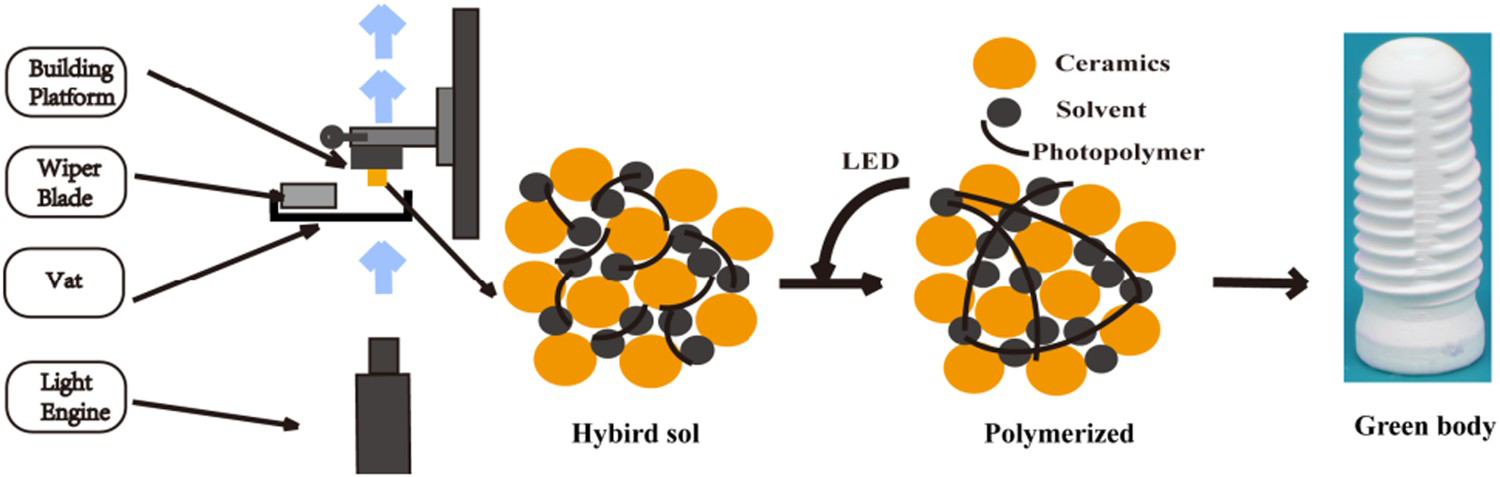
Debinding and sintering process
With various organic additives in the hybrid sol, the debinding of hybrid green bodies usually lasts longer than traditional ceramic processing. With prolonged soaking time at different temperatures based on the amount and decomposition behaviours of corresponding organics, the points for holding temperature could be decided by thermal analysis. Here debinding process was performed by slowly heating up to 523°C for complete organics removal, and further pre-sintering at 800°C with a soaking time of 1 h. Then, the final sintering process was conducted with a maximum sintering temperature of 1450°C in air. The whole process usually takes days.
Microstructure characterisation
The structural features, such as particle packing, grain growth and interlayer coherence evolution during the sintering process, were characterised on the debound and sintered parts using field emission scanning electron microscope (TESCAN MIRA 3LMH, Czech Republic) at different magnifications. An argon ion beam cross-section polisher (IB-09020CP, JEOL, Japan) was used in the preparation of well-polished cross-section sample for SEM observation.
Results and discussion
Structural inhomogeneity
Figure 2(a) shows a photo of the AM-fabricated hybrid green body. Sufficient debinding and sintering procedure should be provided for obtaining dense parts (Figure 2(b–d)). There was no war page observed from the surface, with some kind of structure colouring phenomenon (Figure 2(c,d)).
Additive manufactured Y-TZP dental bridges after (a) printing, (b) debinding and (c) sintering. (d) Corresponding change of the size of Y-TZP dental implants after each step.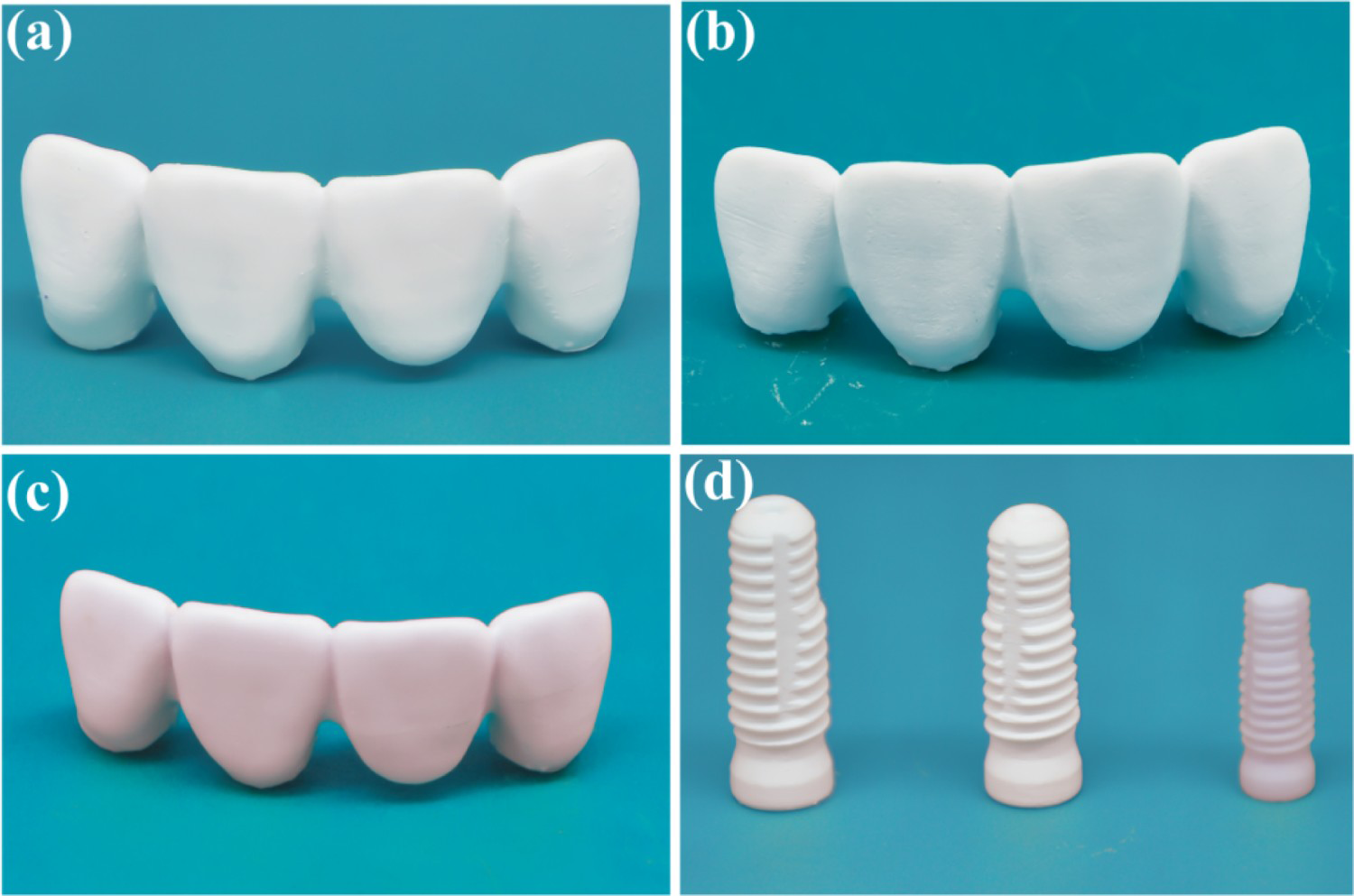
The precision of final products mainly depends on the homogeneity of hybrid sol, the layer thickness along the z axis, the resolution of light exposure on the x–y plane, and the shrinkage during curing and densification in debinding-sintering process, while material experts mainly pay attention to the first and the last issue. Although researchers have been working on better dispersion of hybrid sol, local inhomogeneity could hardly be prevented as the nanoparticles with high surface energy have strong tendency to form aggregates, and under such a highly viscous system with organics taking up about 50% in volume of the whole hybrid sol, those aggregates are hard to be broken down to individual particles again. In our case, those aggregates have similar size of several microns (Figure 3(a,b)), which would lead to further inhomogeneity in printed layered structures as follows. For possible application in prosthodontics, surface precision of about 20 μm is required to ensure marginal fit, so the smaller layer thickness, like 25 μm, is preferred in ceramic stereolithography for high marginal precision in dental use. However, this value is close to the size of observed aggregates on scale, so local aggregates would severely deteriorate the smoothness for the printed layer, often leading to a wavy surface and layered structures after photocuring and sintering (Figure 3(c,d)).
(a,b) Aggregates in the hybrid green body of Y-TZP specimen by ceramic stereolithography. (c,d) The layered structure in sintered Y-TZP bridge, having a layer thickness of about 25 μm as set.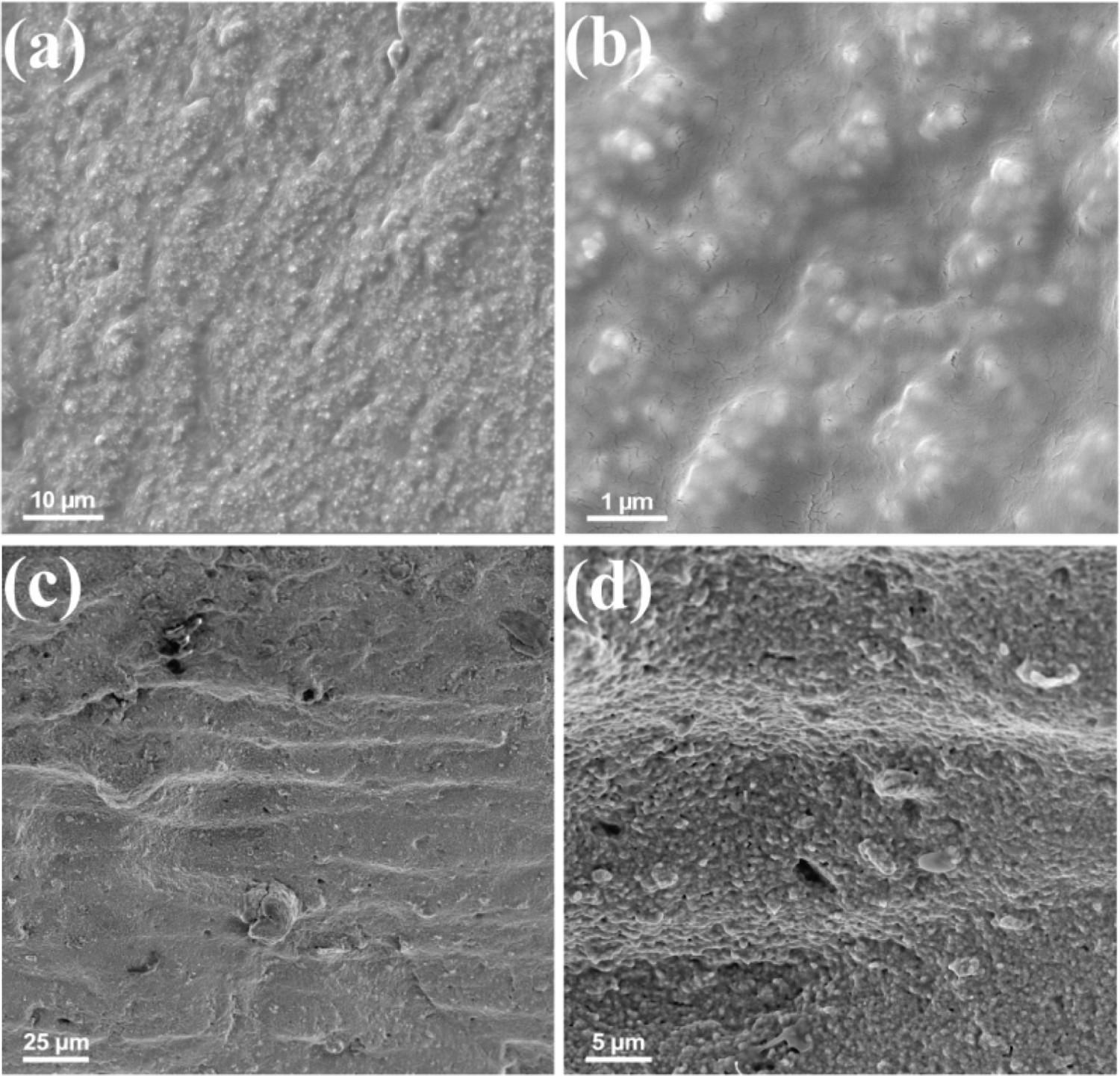
Support structure
Another factor that would influence the precision of the contour of the printed feature is the support structure. For layer-wise ceramic stereolithography, impending sections must be held by extra printed support structure, illustrated by the case of printed bridge as shown in Figure 4(a). Such a support structure is removed manually in current workflow, which definitely impairs the advantage in automation for AM and adds the risk of unexpected damage like scratches. Furthermore, the contradiction for the support structure exists, that must be strong enough to hold the weight of the whole printed feature and allow sufficient adhesion to the building platform, but that also causes the difficulty in removal after printing, considering that they are actually fabricated by the same material as the printed components. Thus, better adhesion in printing often leads to poor final surface quality, like the case shown in Figure 4(b). For prosthodontics, those damages would severely deteriorate the aesthetics (when they appear on the front side) or occlusal contacts (when they appear on the bottom side).
(a) The printed Y-TZP bridges with support structure on the bottom. (b) The damage on the bottom surface of the printed Y-TZP bridge after removing support structure.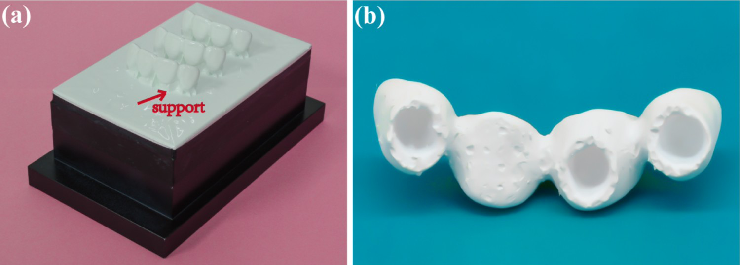
Delamination and cracking
The occurrence of observable cracks often represents the failure of a structural material. Unfortunately, there is a big chance for such failures to form in this layer-wise fabrication manner. In the case shown in Figure 5(a,b), the cracks are observed on the outer surface of the sample, with a certain propagation orientation, but there is no crack on the inner surface. This feature could be interpreted by stress distribution: The outer crack is subjected to tensile stress from the surface, while the internal surface is subjected to compressive stress. Thus, the crack would likely to originate from the junction section of the bridge, as a possible weak point, and propagates along the direction where the surface energy decreases under the action of tensile stress (Figure 5(b)). Besides, the tendency of crack formation could be further enhanced by the layer-wise building manner, that is, when the gradient of stress is parallel to the xy plane, the weaker interlayer bonding strength, compared to the one within a single layer, could act as possible propagation route for cracks to finally become fatal.
(a) The photo of a Y-TZP bridge after debinding containing cracks. (b) The SEM image revealing the cracks observed on the sintered Y-TZP bridge.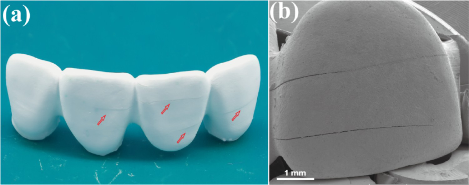
Microscopic defects
Even with special care to prevent those obvious features mentioned above as macroscopic defects, one may still notice the differences in appearance compared to commonly used ceramic prosthetics. For example, the sintered 3D printed Y-TZP samples appear as opaque, and sometimes with specific colour, like purple in Figure 3(c,d). Both features lie in microscopic defects, basically different structure of distributed micropores that is often unobservable by density measurement.
A representative cross-section feature of a fabricated component is shown in Figure 6, in which we could find two kinds of pore structures: smaller ones of 200–400 nm and larger ones with several micrometres in size. The former ones are distributed all over the whole horizon, which could be ascribed to the residual porosity due to the unfinished densification. The high organics load in hybrid green body means a low packing density for ceramic nanoparticles after debinding (about 40% of TD), which yields a much larger sintering shrinkage than traditional ceramics. On the microscale, it means the necking and final grain growth would take higher energy with prolonged soaking time, let alone the inhomogeneity by aggregates and networks of organics mentioned above. So, we would regard these small pores as normal defects, which could possibly be eliminated by prolonged sintering, and that would lead to a better transparency. By the way, these small pores of such a high density may account for the purple appearance, as we did not find any impurities that could act as colorant by energy dispersive spectroscopy (EDS). Tailored nanostructure is known to bring about special light absorption/reflection characteristics, and as for those randomly distributed small pores, the size of 200–400 nm is in accord with the wavelength of violet light, thus the specifically enhanced violet light reflection or interference could be suggested, leading to such a structural colouring feature [11].
(#a–d) The sintered Y-TZP products with pores and abnormally grown grains, (e) EDS of the abnormally grown grains.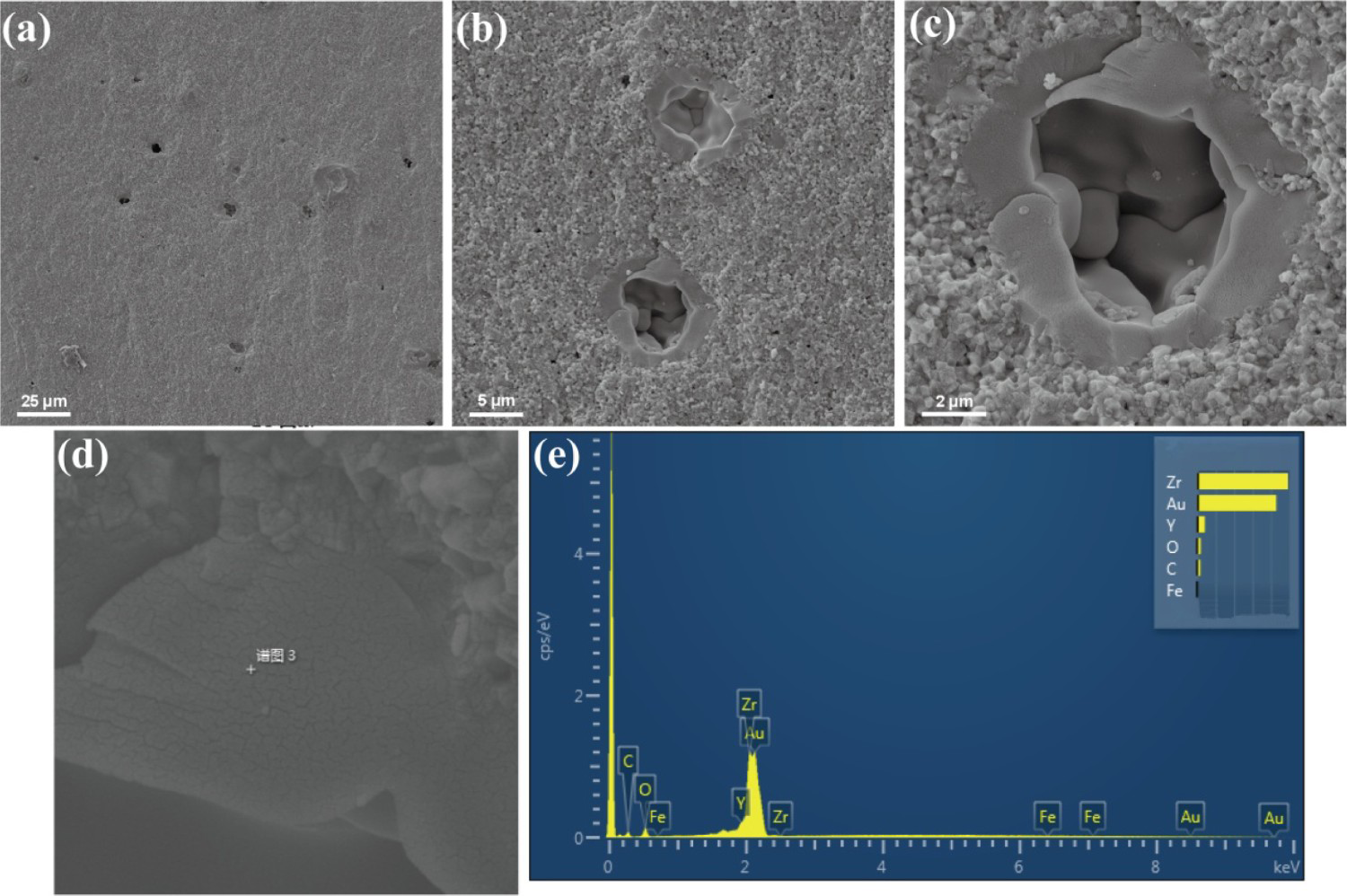
The emergence of larger pores is more abnormal, as shown in Figure 6(c) and Figure 7(c). The results of EDS did not reveal any impurities again on the pore site, so we would suppose that they were actually bubbles formed at the edge of the scraper during the rotation movement with highly viscous hybrid sol. The size of these pores is far beyond the degree that can be eliminated by normal sintering and grain growth. Some significantly larger grains observed around those pores may be interpreted as the results of free-surface accelerated abnormal grain growth leading to such pores with high coordination number [12,13].
The argon ion-polished surface of sintered specimen. (a,b) The presence of abnormally larger pores in micron size under lower magnification. (c) A typical larger pore with some nanosized pore around under higher magnification.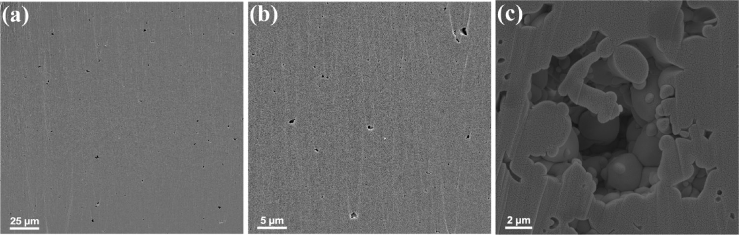
Compared to those macroscopic defects which often cause direct failures, microscopic defects may not be obvious, but have strong influence on the mechanical performance of the components in the long term, especially for those large pores that could act as preferable crack initial points according to the Griffith fracture theory [14]. This observation might explain why stereolithography fabricated Y-TZP specimens lack high strength. Y-TZP is well known by its high strength and toughness in ceramics. It can achieve a bending strength of 900–1400 MPa by pressureless sintering and 2400 MPa by hot isostatic pressing [15-17]. In comparison, a 4-point bending strength of 650–850 MPa was reported for the 3D printed Y-TZP specimens after sintering [18,19]. Although this value has exceeded the minimum requirement set by the ISO standard for dentistry application [20], the obvious low strength still indicates that the mechanical performance is strongly affected by the microscopic defects, which might cause failures of restorations in the oral environment particularly by countering in the cyclic loading condition.
Conclusions
The invention of ceramic stereolithography does make a great contribution to the AM of ceramic components in general and the fabrication of all-ceramic prostheses in particular. However, several technical barriers have to be overcome in order to apply the 3D printed all-ceramic prostheses to clinical practice through tailoring the microstructure of the printed and final sintered components towards components with competitive aesthetics and mechanical performances. Important issues in ceramic stereolithography that should be taken into consideration include (1) optimising the composition and preparation methods of the hybrid sol towards higher structural homogeneity; (2) updating the data processing techniques towards better matchup of layer parameters and support design; (3) developing debinding-sintering methods towards higher efficiency and full densification. Only when the successful solutions to these problems are established, the suitable, reliable and affordable 3Dprinted ceramic prostheses would become applicable to the patients.
Footnotes
Disclosure statement
No potential conflict of interest was reported by the authors.