
Abstract
Limb disability is one of the serious problems and rehabilitation of lower limb requires an assistive force to the patient. A new design for stationary trainer for performing rehabilitation therapies for lower limb at the knee as well as hip joints in the sitting/lying positions is presented in this article. A passive orthosis (similar to an exoskeleton) is suggested in this system to provide a support to lower limb of the patient. The suggested mechanism also comprises of an active Cartesian manipulator based upon a spatial three parallel prismatic–revolute–revolute–revolute kinematic arrangement to perform the required limb therapeutic motions in the transverse/horizontal/lateral and sagittal/longitudinal plane. Numerically, the usefulness of the designed stationary trainer is confirmed using computer-based simulations along with a motion control scheme by performing various clinically suggested therapeutic motion tracking (passive range of motions) tasks. The article demonstrates the accomplishment of the control scheme for various training procedures of the lower limb.
Keywords
Introduction
Limb disability is one of the serious problems seen widely among the elderly (which may soon become an issue for the middle aged group as well). 1,2 Stroke is the leading cause of limb disability which in turn will lead to gait disorders, 3,4 geriatric disorders, and physical disabilities. 5 For those beyond the age of 55, the lifetime stroke risk is 1:5 in case of women and 1:6 for men. 6 India is facing acute flaccid paralysis which cannot be clinically differentiated from polio paralysis. It is twice as deadly as polio paralysis and takes longer duration to recover. 7
Rehabilitation of lower limb necessitates an assistive force to the patient. 8,9 Robotic assistive devices have been the topic of discussion in the past few decades. 10,11 Such devices have been emerging vastly in the medical industry. 12 A new mechanical system for the rehabilitation treatments of the lower limb based on detailed information and compilation of present usage of lower limb rehabilitation robots for clinical treatments is proposed in this article. In the last few years, lower limb rehabilitation (therapeutic treatment) has been the focus of discussion 13 since automated systems assured effectual results like substantial improvements in patients’ recuperation through robotic physiotherapy. 14 Rehabilitation is body and limb specific and it necessitates the requirement of modular and robust mechanical systems for the treatment for the development of such a complex system. However, several patients are in need of lower limb treatments and hence it is very common in the rehabilitation domain. 15,16
These therapeutic treatments help to regain the limb motor nerve activities. Various kinds of training platforms are available. 17,18 However, three kinds of systems are popularly used for the clinical purposes namely rehabilitation system with a body weight support for gait training (GT), overground trainer for regaining the strength and gait, and stationary trainer for sitting/lying type of treatments. 17 For the first two kinds, a certain level of fitness or recovery is required. The latter is more importantly used at the early stage of treatments.
The experimental arrangements/systems available to treat the patients in sitting/lying state include the commercially available Motion Maker. 19 The NEUROBike, 20 Physiotherabot, 21 Supine, 22 Lambda, 23 TEM, 24 NeXOS, 25 HipBot, 26 ViGRR, 27 LLR-Ro, 28 ANKUR I, 29 ANKUR II, 30 i-Leg, 31 Hunova, 32 and AIST-Tsukuba 33 are a few research platforms. Continuous passive motion (CPM) is one of the common therapies in the initial stage of disability when patients have low or no control over limbs. These CPM-based mechanisms are designed to give continuous/repeated therapeutic treatments but mechanisms like Motion Maker, 19 Supine, 22 NEUROBike, 20 and AIST-Tsukuba 33 are unable to perform CPM because of their system arrangement, dynamics, and the structural bulkiness. The Hunova, 32 a very modern and aesthetic design, can perform most of the therapies. But it is a quite expensive system and not applicable for bedridden patients. In the Lambda mechanism, 23 actuators are located outside the patient’s limbs without any orthosis system. Therefore, it does not provide a proper support to patient’s limbs. The NEUROBike 20 is an end-effector/foot-plate-based serial mechanism to perform lower limb rehabilitation treatments. The Physiotherabot 21 is an orthosis-based mechanism statically balanced (gravity balancing) using the counterweights to reduce the actuator effects easing the physical efforts of physiotherapists. The Supine robot 22 provides self-locking behavior on its linear actuators due to their high mechanical advantage but workspaces are restricted due to larger stroke length of the linear actuator. Systems like Lambda, 23 NEUROBike, 20 ViGRR, 27 and AIST-Tsukuba 33 don’t have any orthosis systems.
Lower limb rehabilitation devices generally have motion in sagittal plane. 11,19–23,25,27–30,34–36 Although many therapies need off-planar movements, complexity of the arrangement and safety of patients are major concerns. 17,18 The various therapeutic treatments and their associated motions are presented in Figure 1, of which hip abduction and adduction are very important. The knee movements include flexion and extension too. 37 For performing these therapies, only a few attempts have been made. 21,26,33,38 Hipbot 26 is designed to give off-planar motions to the lower limbs in lying posture. However, it can only provide adduction–abduction away from the body and not toward the body. Despite the compact system, it is bulky and difficult to perform treatments in ease. To address these issues, a Cartesian manipulator can be used. But, serial configuration-based Cartesian manipulator namely prismatic–prismatic–prismatic or Gantry type mechanisms are too complicated to execute the lower limb rehabilitation applications. Therefore, in the literature, 38 an attempt is made using Orthoglide, with a spatial three prismatic–universal–universal (3-PUU) parallel configuration. The fixed base of the parallel manipulator placed on the ground complicated the motions restricting full knee extension and hip abduction. To overcome the above limitations, in this work, the popular Cartesian parallel manipulator Tripteron 39,40 is used. It consists of three legs each having a prismatic–revolute–revolute–revolute joint arrangement with the prismatic joint active and each leg which mounted on the base platform. 39 The major difficulty in off-planar movement is the movement of the actuator assembly as they are mounted in single plane. So here the proposed system is combining a parallel manipulator based on Tripteron with a serial passive orthosis which can render four degrees of freedom to the lower limb.

Lower limb therapeutic treatments and their associated motions.
The main motive of the system designed in this article is to execute the most essential rehabilitation therapeutic treatments like abduction, adduction, flexion, and extension of the hip joint and, flexion and extension of the knee joint using a modular Cartesian manipulator along with a simple motion controller. The variation in the joint angles at the hip and knee causes these motions. The hip abduction/adduction occurs by the variation of the waist angle, hip flexion/extension due to the hip angle, and the knee flexion/extension occurs due to the knee angle variations. The suggested system would easily perform the combined motions and is capable of adapting depending on the features of the legs. The suggested system can perform therapeutic motions for one leg at a time. The technical contribution and novelty of the suggested system is its simple and modular mechanical configuration rather than a complex robotic system. Furthermore, only linear actuators are used in the stationary trainer to fulfill the required hip and knee motions. Therefore, it assures the system stability, safety, and robustness for rehabilitation tasks.
Conceptual design
The suggested stationary trainer consists of a passive orthosis based on a serial four revolute joint kinematic configuration, an active foot-plate/end-effector operated by the driving manipulator based on a spatial 3-

Conceptual design of the proposed stationary trainer.
The rotation angles and speeds of the limb joints are chosen for the system design based on the clinically acceptable range of motion. The variability of the patient’s height and weight is also considered during the design process. The suggested stationary trainer should be working within these constrained or restricted limits. If not, the emergency protocol is executed. In addition to this, this program has a proactive safety process that will constantly validate the given desired motion so as to make sure the healthy/possible motion of the patient’s limb which, in turn, will make sure that the patient does not get hurt during the therapeutic treatments.
The waist, thigh, crus/calf, and foot of the limb correspond to the four bodies or links of the passive serial orthosis. All of these bodies are interlinked with the help of four rotary joints: two at the hip joint and one each at the knee and ankle joint positions. The suggested passive orthosis along with the end-effector can be seen in Figure 3. The kinematic relationship of the passive orthosis is given as below


Kinematic configuration of the passive othrosis (along with patient’s lower limb).
where
Although the seating arrangement has a profound effect on the efficacy of the rehabilitation process, it is not considered as an explicit factor in this work. Instead, the seat position has been considered as waist or hip joint location indirectly (point H in the Figure 3) reducing it to a known variable in the kinematic model of the suggested mechanism.
The beauty of the Tripteron manipulator is that it provides the Cartesian motion in space with simple kinematic relationships and the Jacobian of the mechanism forms an identity matrix. In the initial design, the end-effector or the foot-plate was placed downward side, but this design restricted several rehabilitation motions by link interference, therefore, by analyzing the system completely, the end-effector has the foot-plate attachment on top of the end-effector square plate. In addition, the link lengths of each leg were obtained by considering the required workspace as a cubic volume with a side length of w. The extreme reach or location of each leg end from the origin would be
The kinematic configuration with the joints and links of the suggested Cartesian manipulator is depicted in Figure 4. The three mutually perpendicular (as given in Figure 4) prismatic joint displacements are indicated as r
1,r
2, and r
3, respectively. The 3-
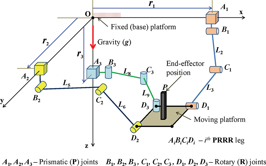
Kinematic configuration of the 3-
The inverse (indirect) kinematics of the parallel mechanism gives the linear displacements which are the inputs as given in equation (3). The vector

Kinematic configuration of the

Kinematic configuration of the

Kinematic configuration of the


where

The functional and working principle of the suggested system is as follows: The first step as a preprocessing task is to make the patient consult a physiotherapist who recommends the required therapeutic procedures (types of movements, duration, repetitions, etc.). At the stationary trainer side, a statically (gravity) balanced passive orthosis would be adjusted as per the patient’s limb and strapped properly tightened along with supporting frames. The initial set of treatment would be conducted by the expert and the motion of the treatment would be recorded along with the time histories of the limb angles. Based on these inputs, the mechanized/automated treatment would be performed with the help of the suggested stationary trainer. The training parameters like trajectory, training mode, and duration of training must be set by the attendant/supervisor prior to the passive range of motion (PROM) including GT. Once the training begins, the joints follow a predefined path according to the parameters given. In case of emergency, a switch that can be operated by the patient as well as the therapist/attendant is provided. This will interrupt the working of motor and the control signals will get cut off. As the suggested lower limb rehabilitation mechanism is operating using linear ball screws, the chance of immediate collapse of the system is little. The current joint positions will be retained for the safety of the patient in case of emergency.
Dynamic model and motion control scheme
Dynamic model
Recognizing the consequence and significance of the input forces (joint efforts) on the mechanism’s motion, understanding these effects on the other components (links and joints) are critical. In other words, the relationship between the input forces (cause of motion) and the motion or system behavior is important to understand the nature of the system and to facilitate the control. It can be obtained with the help of any dynamic formulation methods and in this proposal it is proposed to use the Euler–Lagrange method for obtaining the equations of motion of the driving mechanism. It is assumed that the bodies and joints are rigid, and the total energy comes from the kinetic energy and potential energy of the system components. There are 13 bodies including the moving platform (end-effector) and lower-limb. The summation of individual potential and kinetic energies of the elements gives the total potential and kinetic energies of the system. They are given along with the Lagrangian as follows

where
The joint forces of the system are evaluated and expressed in equation (8)

On the basis of Euler–Lagrange dynamic formulation, the dynamic motion equation of the stationary trainer is expressed in state-space form as given in equation (9)

where


where
Motion control scheme
To obtain effective repetitions of the task-specific lower limb rehabilitation therapies, the stationary trainer has to be controlled. For this, the system uncertainties have to be overcome for which a motion controller has to be synthesized. This will further reject the disturbances generated by the system and the patient. In the course of the therapeutic processes, the limb masses of the patients and location of the center of masses are not known accurately. The control scheme becomes complex due to friction and other undesirable effects. The passive orthosis with patient’s lower limb is joined to the spatial manipulator which is active. Hence, designing the model of the overall system including all the subsystems is challenging. This is because the overall performance of the system is partly influenced by some dynamics that is not modeled. Therefore, in the proposed closed loop tracking mechanism, the stationary trainer is controlled with the aid of a simplified proportional-derivative (PD) controller along with gravity compensation.
42
This robust control is based on the dynamic formulation of the manipulator. The PD controller is used because it is simple to realize and can calculate the desired control activity based on the joint space position errors and error derivatives. The known gravity vector,

where
The suggested stationary trainer together with the motion controller is presented as a flow diagram as shown in Figure 8. The therapeutic treatments upon the recommendations of the physiotherapist/expert are considered for the stationary trainer. In the current work, only hip and knee joint motion therapies are focused which includes the GT. These therapeutic motions can be captured during the personal treatment by the physiotherapist. The desired motion of the lower limb joints along with the orthosis/exoskeleton is planned further depending on the configuration space variables using kinematic relations of the stationary trainer. Depending on the desired/required joint space trajectories fed into the controller, it calculates the joint forces required considering the reference state and actual state (using sensor feedback). These fed joint forces are then passed into the low-level actuator controller and instructs the actuator system according to the motion controller inputs desired. The low-level controller of the stationary trainer enables the achievement of the necessary lower limb joints movements. Anyhow, the overall system is monitored and under the control of the supervisor. The patient or the supervisor is able to stop the working of the motor by manipulating the emergency switch. Once the switch has been activated, the motor becomes idle immediately and the control schemes stays invalid simultaneously.

Flow diagram of the stationary trainer along with the motion controller.
The therapists usually refer certain specific lower limb range of motion (ROM) tasks for each joint. Such tasks aim to gradually increment the range of motion giving due consideration to the swelling, pain, and stiffness which is present. These motion therapeutic tasks are generally classified in three ways 43 :
Active range-of-motion (AROM): These therapies are performed without any assistance.
Active assistive range-of-motion (AAROM): In this task, the therapist/attendant helps the patient to perform without any difficulty (very similar to the gym trainer). The assistance is required to support the weaker muscles and may avoid any discomfort to the patient during the movements.
PROM: In this, the therapeutic motions are performed purely by the therapist or the equipment by moving the joints as per the prescribed manner without any effort from the patient.
In this article, the PROM therapeutic tasks are considered; however, the suggested stationary trainer is capable of performing other two types as well by adding the necessary subsystems.
Performance analysis
Performance or functional analysis ensures the desired level of performance of the system, exhibits the utility of the suggested stationary trainer, facilitates the physiotherapists to execute their rehabilitation training in a better manner, and provides improved working conditions. The proposed stationary trainer focuses mainly on the repetitive motion tracking tasks such as abduction, adduction, flexion, extension, and GT to a certain extent as the proposed stationary trainer is designed for executing rehabilitation therapeutic procedures on lower limb, specifically at hip and knee joints. Thus, the efficacy of the trainer is demonstrated by motion tracking of various desired trajectories according to the clinical gait data. The following subsections present the elaborate descriptions along with the discussions of these analyses.
Details of the simulation, system, and task parameters
The suggested trainer is designed to execute therapeutic procedures at the hip (abduction/adduction and flexion/extension) and knee (flexion/extension) joints. The clinically suggested angle ranges for these motions as per the orthosis joint angles are as follows: waist angle (for abduction/adduction):
The proposed system and its kinematic arrangement are designed to perform rehabilitation therapies of an average person based on the standard anthropometric data. The conceptual design of the stationary trainer consists of active lead screws which can compensate any gravitational loads. These active lead screws can push or lift the patient’s leg which may weigh up to 200 kg. The proposed system is able to accommodate patients’ heights ranging from 1.5 m to 1.8 m. The system can also perform therapeutic procedures for both right and left legs without having to move the patient from the seat. Each linear guide way is having a length of 2 m, the individual axis leg’s link lengths are 0.9 m for the first link (which is connected from the base joint) and 0.8 m for the second link (which is connected to the end-effector). These leg lengths can be adjusted by using telescopic rod arrangements. Based on the current design, the system can cover up to a cubic work volume of
For the system’s complete functional demonstration, there are four kind of therapies and their associated motions considered. The first one is a CPM and it is considered as one of the primary therapies in the lower limb rehabilitation. In this therapeutic motion, the ankle point or the foot is moved to and fro in the longitudinal (x) axis. The joints at the hip and knee are in motion with the help of only one axis movement. The second one is very similar to a clinical GT except that the ankle joint motions are on the sagittal plane. In this, the hip and knee joints would get flexion and extension motions. Further, during this therapy, the lateral (y) axis movement is fixed (constant). The third one is combining the hip abduction and adduction. The whole limb would move in the transverse plane and in this the vertical (z) axis movement is fixed (constant). The final one is a complicated one which combines the hip abduction/adduction and flexion/extension motions. This therapy is of advance level and there is motion in all three axes. It is indeed a good task to justify the feasibility of the suggested stationary trainer.
The system and physical parameters of the system to perform computed-based simulations are given in Table 1. The link lengths of thigh and crus are the distances from hip to knee joints and from knee to ankle joints, respectively. The former is chosen to be 0.5 m and the latter to be 0.45 m for numerical simulations. The mass of the thigh and crus/calf are 8 kg and 7 kg, respectively.
System and physical parameters used for the simulations.

Workspace analysis
Workspace study is an important tool to decide the architecture of the mechanism. It is usually an intermediate step to learn the workspace but a crucial one to analyze the manipulator. The workspace investigation 3-
The workspace of 3-

Singularity-free and collision-free workspace of the manipulator.
Case 1: CPM
For performing this case of therapy, the lower limb of the patient along with the passive orthosis is located in the sagittal plane. In this therapy, the leg would move from its closed to normal/extended position to almost its completely folded position; however, the leg movement would take place in only longitudinal axis.
47
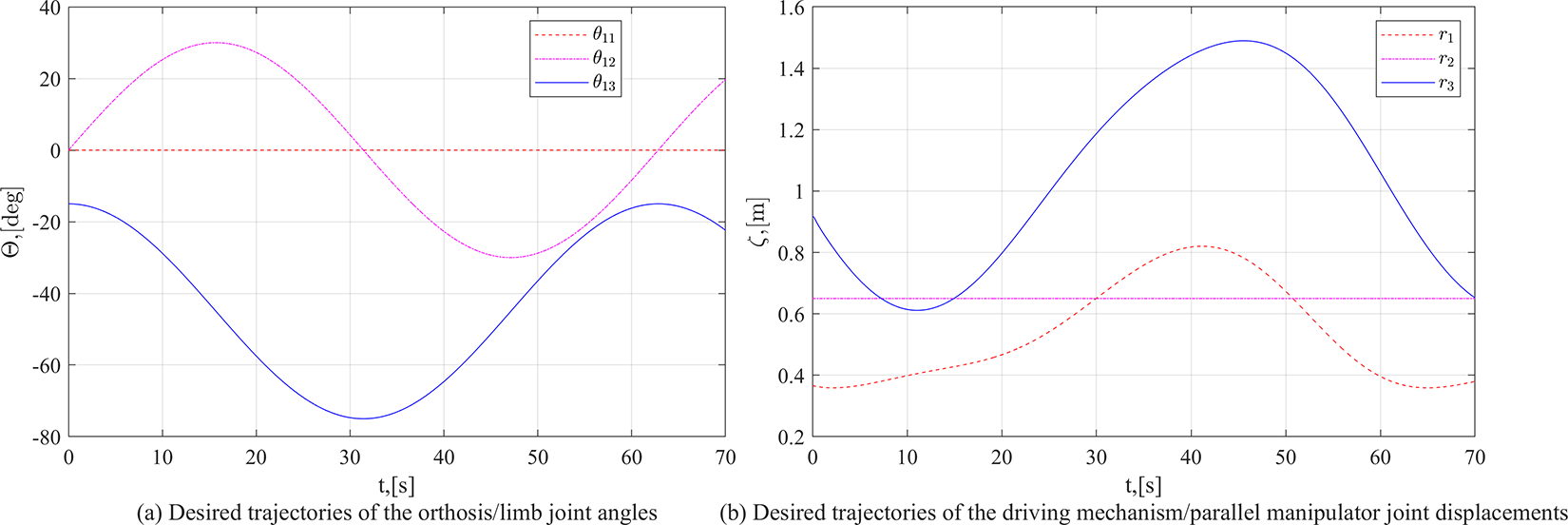
This type of motion would give combined hip and knee flexion–extension movements. The description of this therapy is presented in Figure 10. For the simulation purpose, the displacement in the longitudinal (x) axis, that is, the configuration variable r
1 would be varied in a sinusoidal manner starting from 0.5 m to 1.0 m. The corresponding desired joint displacements of both the active driving mechanism and the passive orthosis are plotted in Figure 11. The circular frequency of the joint movement is fixed as 0.1 rad/s (approximately
Possible orthosis movements during a continuous passive motion therapy.

Desired trajectory used for a continuous passive motion therapy.
Case 2: Gait training
In this case of therapy, the joints at hip, knee, and ankle are moved so as to follow the gait pattern. Since the suggested system is focusing the hip and knee joints, the GT case contributes the motion associated in x and z axes.
48
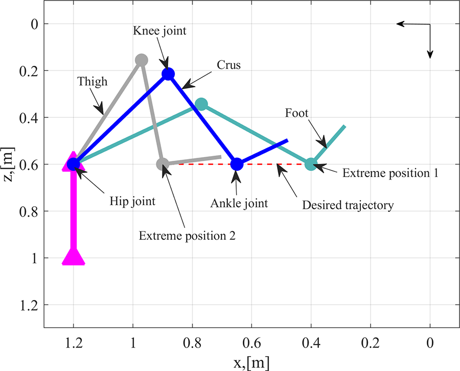
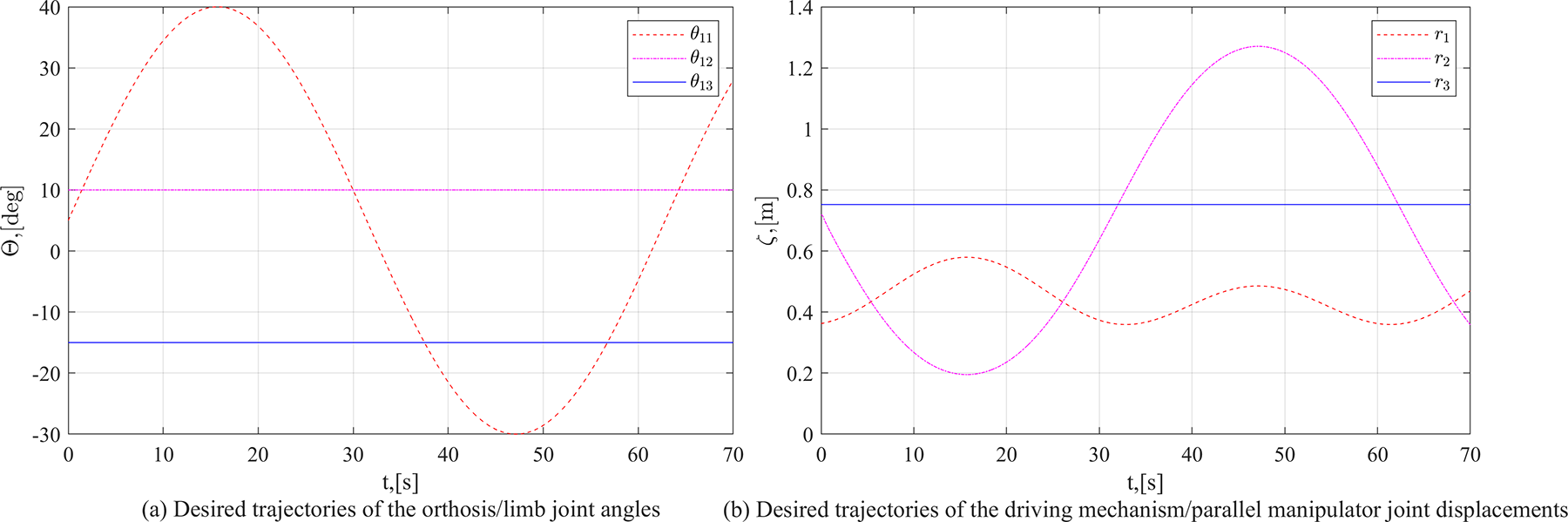
The CPM case is a single axis movement case and the GT is a planar case with two axes movement. The pictorial description of this therapy is given in Figure 12. For the simulation, the hip joint angle

Movement of orthosis during a gait training task.
Desired trajectory used for a gait training.
Case 3: Hip abduction and adduction
In this case of therapy, the lower limb is moved in the lateral directions or sideways. For performing the abduction and adduction, the hip joint has to be rotated about the vertical (z) axis. This particular hip joint is indicated as waist angle (

Orthosis movement for the hip adduction and abduction therapies.
Desired trajectory used for the hip adduction and abduction therapies.
Case 4: Hip abduction/adduction and flexion/extension
The lower limb is moved in the lateral and longitudinal planes, in this case to perform the combined therapeutic motions of the hip. This particular therapy is an advanced one and concentrated at the hip joint and covers all possible motions of the hip joint except the hip internal and external rotations (which are not commonly suggested therapies). Since, the suggested system is focusing on all the possible hip joint movements, the mechanism has motions in all three axes. The pictorial description of this case is given in Figure 16. For the simulation, the waist angle

Orthosis movement for the combined therapies of the hip joint.

Desired trajectory used for the combined therapies of the hip joint.
The performance analysis of the proposed stationary trainer is done by running the dynamic simulations with different working conditions using MATLAB under standard parameters and Runge–Kutta fourth-order (rk4) numerical integration method or ordinary differential equation (ode) solver is used with an update rate (sample time) of 100 ms. The simulations are performed on a laptop computer (having an Intel core i5 processor and 8 GB RAM) and the version of the MATLAB package used is 2019a. The four abovementioned simulation cases along with their desired motions in the simulated environment is presented in Figure 18.
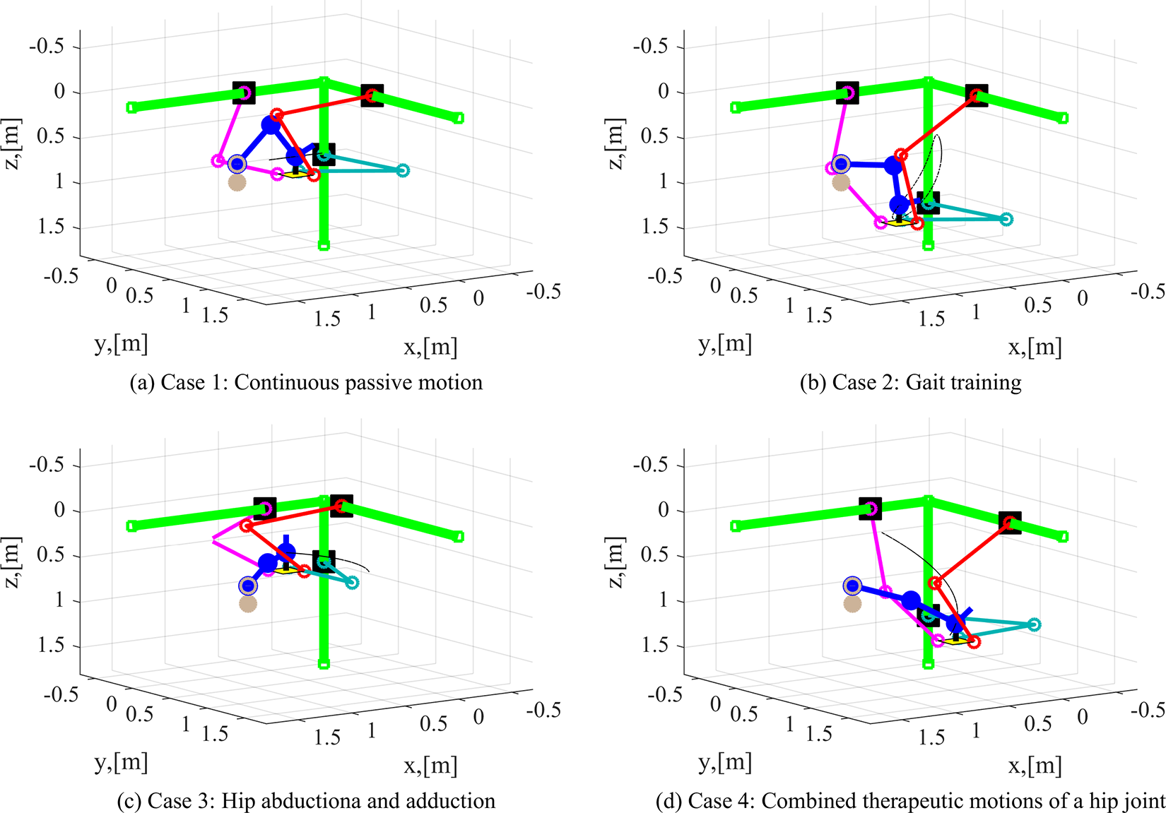
Desired therapeutic motions along with the suggested stationary trainer in the simulated environment.
The overall performance and the choice of the control parameters would be affected based on the actuator characteristics. In this article, the actuator dynamics is considered as a first order system with a time constant of unity.
To get an appropriate control parameter namely,

The results of the parameter sensitivity analysis are given in Figures 19 and 20. Figures 19 and 20 present the norm of tracking joint position errors and norm of input forces, respectively.

Time trajectories of tracking errors for variations in controller parameters.

Time trajectories of joint forces for variations in controller parameters.
It can be observed from the results that, with the increment of the value of
Results and discussion
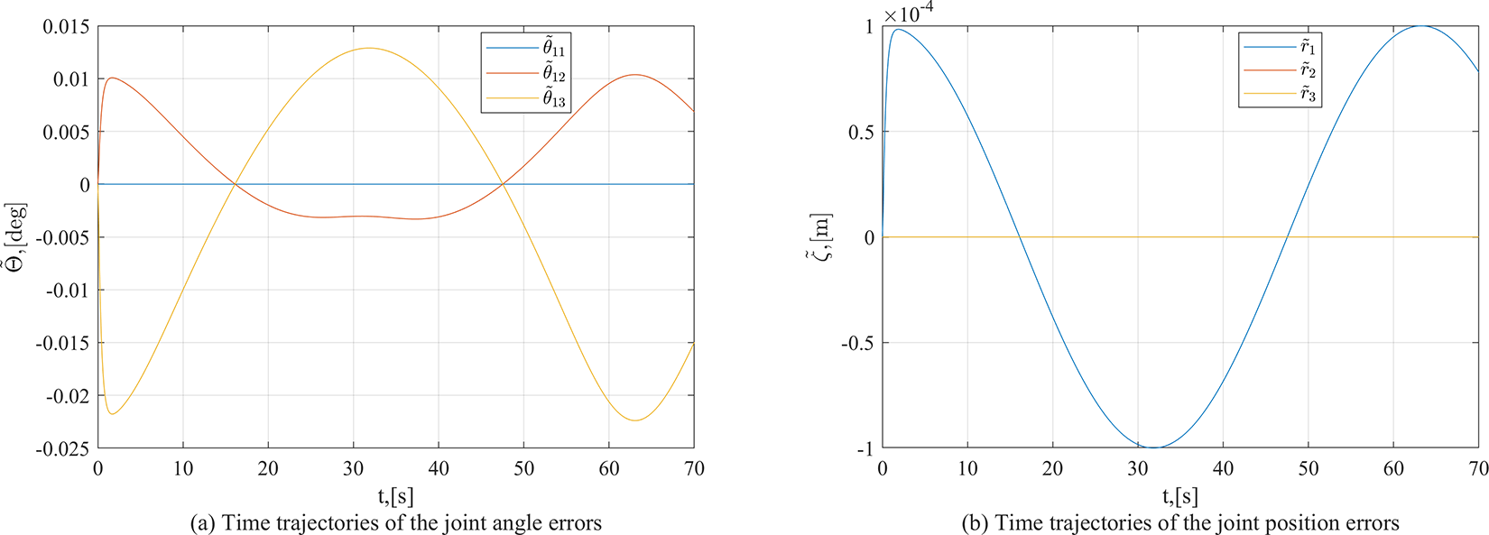
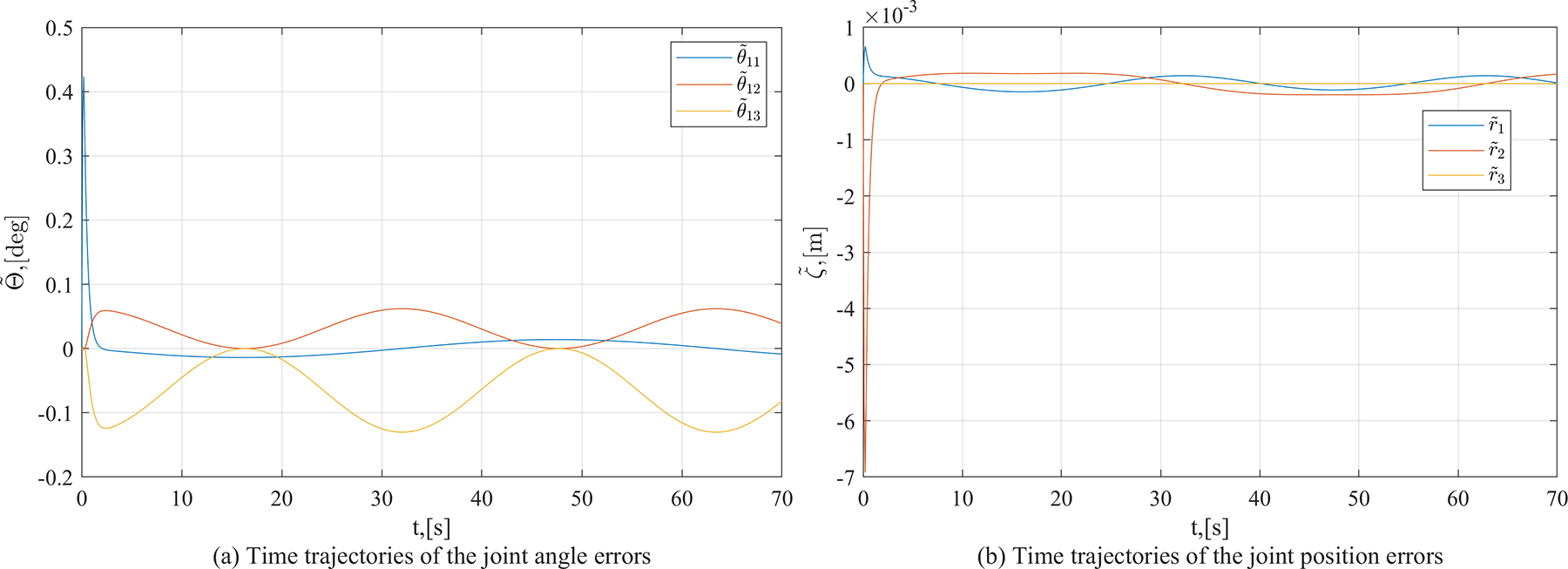
The simulation results of all four cases are presented in Figures 21 to 25. These results exemplify the contribution of the suggested stationary trainer in lower limb rehabilitation therapy, besides, its motion control scheme accomplishment. These results are having two parts, one is the tracking position errors and the other is time history of input forces. The plots of tracking position errors have the joint angle errors of the orthosis rotary joints and the displacement errors of the driving mechanism prismatic joints angles.
Tracking errors for the continuous passive range of motion therapies.

Tracking errors in the gait training task.
Errors in the hip adduction and abduction therapeutic motion tracking task.

Errors in tracking the combined therapeutic motions of the hip joint.
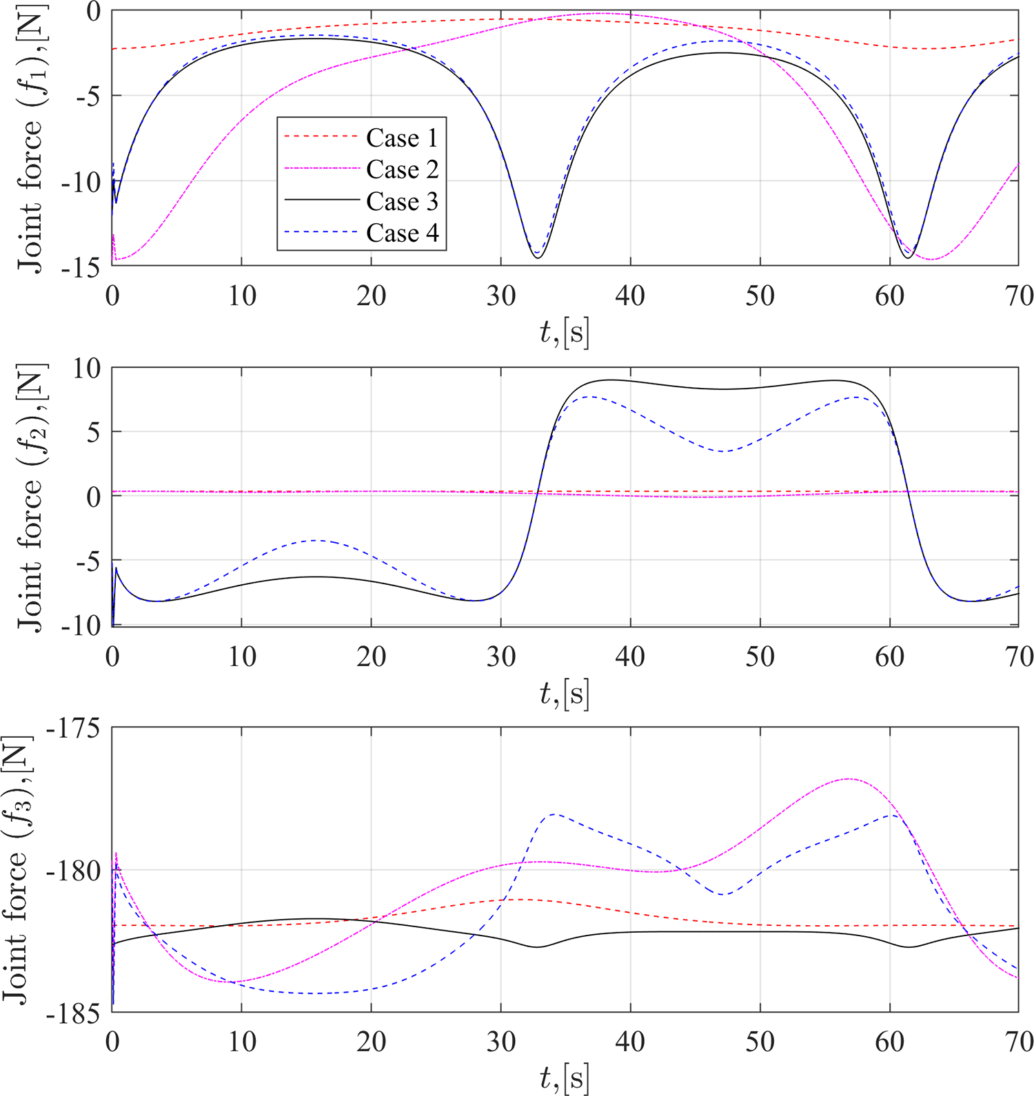
Time trajectories of the joint forces for all four cases.
During the CPM case, the driving unit has only one axis movement; therefore, the tracking errors are more in one of the joints and can be seen from Figure 21. However, the lower limb joints are moved in the sagittal plane, the hip and knee joints have flexion and extension. The joint angle errors in these two joints are more (refer Figure 21) but within the design limits (
However, in all the four cases, the tracking position errors at the initial stage (time t = 0 to 2 s) are high as compared to other times. This is due to the non-zero initial velocity to reach the starting point of the profile. This can be avoided, in case of further research, by not considering this period of reaching the initial point of the profile. This initial error is due to the control action, that is when the system at rest, the actuator starts from its constant input force to the desired force but the nature of this transition affected by the actuator characteristics and in this article it is the time constant of the actuator. Further, the PD control behavior also creates this kind of performance which is acceptable in the control community. The initial peak in the error profiles is due to the chosen desired trajectory as well, it is having non-zero initial velocity. Further, as mentioned earlier, the actuator needs to start from rest to the commanded force (in this article, the actuator dynamics is considered as a first-order dynamic system). This initial error peak can be reduced by making the system start from rest and reach a certain home position and be commanded to follow the given desired trajectory following a sinusoidal acceleration profile or similar kind of profile where the initial desired acceleration and velocity are zero and the initial position errors are also zero. However, the current work is trying to demonstrate the proposed system and its motion control scheme, so these controller improvements are left for further research.
Figure 25 shows the input forces of the linear joints,
Robustness analysis
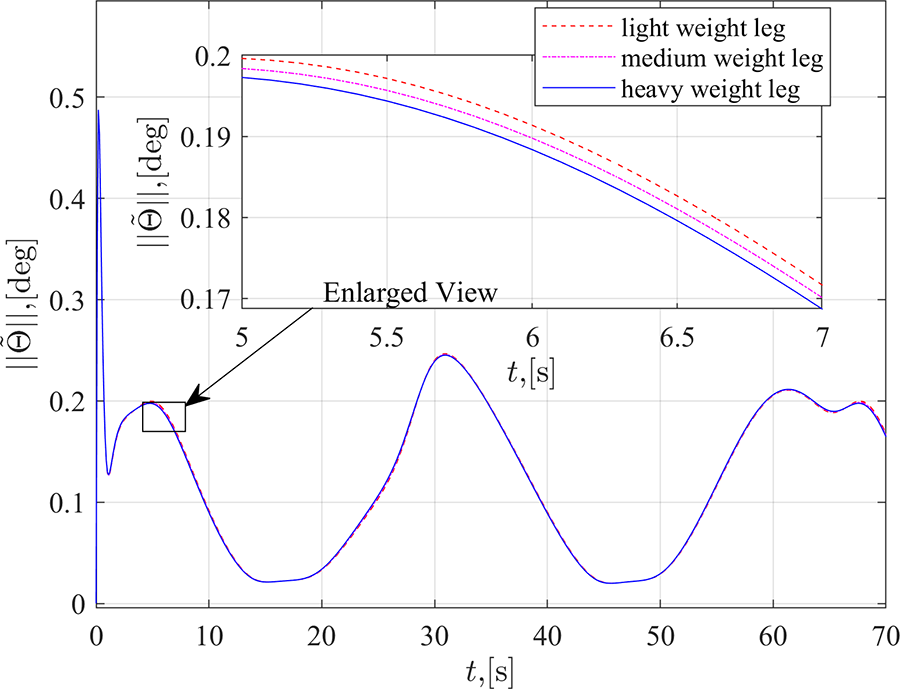
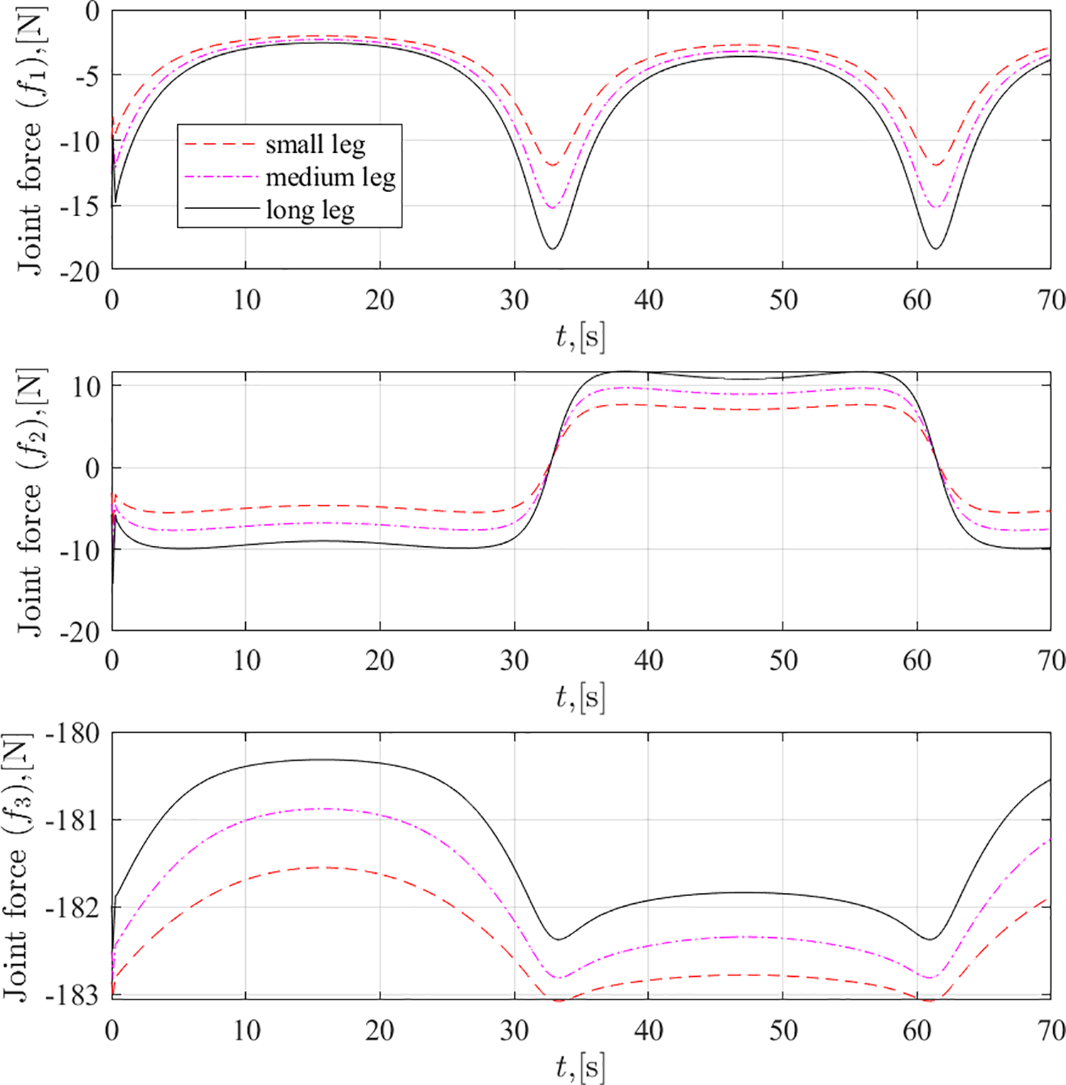
The above presented results confirm the efficient performance of the suggested stationary trainer. However, for examining the system adaptability to the variations in system parameters and patients’ features, three more studies are conducted. For these three simulation studies, case 4 simulation conditions are taken. For the first one, the lower limb or link masses are varied from 0.75 to 1.25 times their assumed value. The results of the simulation studies are given in Figures 26 and 27. The second one is to examine the adaptability of the limb length (to the height variations) and the lower limb or link lengths are varied from 75% to 125% of their assumed values. The corresponding simulation results are given in Figures 28 and 29. The last one to check the potential of the system toward the variation of the speed of the therapy. The circular input frequency is varied from 5°/s to 15°/s and the simulation results are presented in Figures 30 and 31.
Time trajectories of the tracking errors for variations in the limb mass.

Time trajectories of the joint forces for variations in the limb mass.

Time trajectories of the tracking errors for the limb length variations.
Time trajectories of the joint forces for the limb length variations.

Time trajectories of the tracking errors for the input frequency variations.

Time trajectories of the joint forces for the input frequency variations.
Figure 26 shows the tracking errors of the joint angles in the passive orthosis system for the lower limb mass variations. In this figure, the light weight corresponds to the 75% of assumed mass values, medium weight corresponds to the assumed mass values, and heavy weight corresponds to the 125% of assumed mass values. The results show that the stationary trainer along with the control scheme performs well in all three cases and there is almost no deviation from one another. The input forces are varying as per the mass of the lower limb. It can be seen from Figure 27.
The similar trend can be found from Figure 28 for the length variations (patient height variations). The results show the tracking errors of the joint angles in the passive orthosis system for the lower limb length variation. In this figure, the small leg corresponds to the 75% of assumed link length values, medium leg corresponds to the assumed link length values, and long leg corresponds to the 125% of assumed link length values. As seen earlier, the results show that the stationary trainer along with the control scheme performs well in all three cases and there is no much deviation from one another. The input forces are varying as per the lengths of the lower limb. It can be seen from Figure 29.
In the above results, the adaptability of the suggested trainer to the variations in patients’ physical parameters like height and weight is illustrated. However, the motion controller and the actuator capabilities can be verified by varying the speed of the therapeutic motions. Figure 30 shows the tracking errors of the joint angles in the passive orthosis system with respect to variation in the therapeutic speeds. The desired motion and its speed is dependent on the input circular frequency or simply angular velocity of the joint. In this figure, the low, medium, and high speeds correspond to 5°/s, 10°/s, and 15°/s, respectively. The results show that the stationary trainer along with the control scheme performs well in all three cases. However, the tracking errors are increasing with the increase of input speeds. However, the input forces are not varying with respect to their corresponding joint motions, and it can be seen from Figure 31.
Overall, it can be observed that the suggested system along with the performance of the motion controller is sound in tracking the required therapeutic motions and the performance in terms of errors are well within the designed limits (lower limb joint angle errors should be within
For complete clinical verification and real-time analysis of the proposed mechanism using proper rehabilitation therapies on a functional fabricated prototype, a few more safety measures are to be considered. But, this article is restricted to only the stationary trainer’s function and focuses on its suitability to the rehabilitation therapies with an appropriate motion control scheme. The clinical trials using the experimental works and clinical data of the system are yet to be performed. This can be considered as an objective in the future with proper extension of the work.
Conclusions
The mechanical design and performance of the stationary trainer based on a Cartesian manipulator is discussed in this article. The prime motive of using the Cartesian parallel manipulator is to execute the various possible lower limb rehabilitation tasks that can be imposed in three dimensional space or in real-time. The proposed stationary trainer provides a larger workspace to execute the required range of motion therapies. It also gives an ease of operation due to its simple design and structure to perform any kind of therapies with different set of patients. The computer-based simulations confirm the functionality and sound performance of the suggested stationary trainer. Although, if an advanced controller is used, the tracking position error would have been further decreased, the proposed PD controller along with gravity compensation gives advantage of being simple to use with the help of low-cost microcontrollers. The next study would make a functional prototype which can replicate the movements of the suggested stationary trainer and this device for rehabilitation will have a strong influence in improving the therapeutic outcomes in the field of lower limb rehabilitation. There is future scope in performing complex therapeutic motions (including active assistance motions) in the real-time along with advanced controllers for providing finite time stability and better results.
Footnotes
Acknowledgments
This research is partly assisted by the Russian Science Foundation (RSF), Russia, the agreement number 19-19-00692 and partly assisted by the Council of Scientific and Industrial Research (CSIR), India, the project number 22(0829)/19/EMR-II.
Declaration of conflicting interests
The author(s) declared no potential conflicts of interest with respect to the research, authorship, and/or publication of this article.
Funding
The author(s) received no financial support for the research, authorship, and/or publication of this article.