
Abstract
In this study, a system for automatically picking mechanical parts required in the industrial automation field was proposed. In particular, using deep learning, bolts and nuts were recognized and geometric information of these parts was extracted. By applying YOLOv3 specialized in high recognition rate and fast processing speed, the recognition of target object, location, and postural information were obtained. The geometric information for the bolt can be obtained by creating two bounding boxes and calculating the orientation vector formed by these center values of two bounding boxes after successfully detecting two individual bounding boxes. Moreover, to obtain more precise geometric information on bolts and nuts, image distortion compensation on the detected object was done after detecting the center value of the bolt and nut through YOLOv3. Based on this result, it was proven that an automatic picking of the mechanical parts using a five-axis robot was successfully implemented.
Introduction
In modern society, factory automation by robots is being conducted extensively. Robots are being used in various process fields such as manufacturing, processing, packaging, and assembly, and processes that involve manual work gradually disappear. 1,2 In particular, robots have become essential in automated processes that require high load-bearing capacity and accuracy. 3 Recently, intelligent robots combined with rapidly developing artificial intelligence have attracted great attention and many studies are being conducted. 4,5 However, in most industries, industrial robots are mainly used to grab or move a target object with a fixed position and posture. This is because the level or cost of technology required to build an intelligent robot system for autonomously handling objects in arbitrary positions is high. 6 Additionally, since the existing automation method requires the complete design of the entire process system from the initial process design stage, it is difficult to respond when addition and correction of the intermediate process is required. In particular, if a variable process structure such as a smart factory is applied more in the future in the industry, the existing automation method will become more obsolete, so it is urgent to secure artificial intelligence-based process technology that can be implemented with relatively easy technology and low cost.
Therefore, technologies such as robot vision have been developed to solve this problem, which refers to a technology that combines a visual sensor with a robot and gives the robot the ability to recognize and identify objects through images. 7
However, to solve complex problems such as bin picking 8 using robot vision, it is necessary to estimate the 3D position and posture of an object, so a high-performance 3D camera sensor is essential. 9 The requirement to use an expensive 3D sensor is a significant obstacle to building an economical automation process, and it is the biggest reason that robot vision technologies are rarely adopted in the actual field even though highly useful robot vision technologies are being developed in various ways. To compensate for this problem, it is necessary to obtain the most accurate object information (class, position, orientation, etc.) using a relatively inexpensive 2D camera. 10 Previously, this work was mainly implemented through the classical image processing technology, but in the 2010s, image processing using deep learning, which is robust to changes in the surrounding environment, has been mainly performed. 11,12
Among the numerous deep learning models, the object detection model performs classification and location detection at the same time. The object detection model is a popular technology because it is useful in real life and professional fields, and it is fast and accessible. So far, starting with the first R-CNN series (R-CNN, Fast R-CNN, Faster R-CNN), various models such as YOLO, SSD, and RetinaNet 13 have been developed, and research on the development of models with better performance are in progress.
However, the object detection model is limited in its application to the actual automated process system in that it can give object class and position information but cannot provide orientation information. For this reason, object detection has been mainly used in cases where only approximate information of an object in the screen such as a security camera or a vehicle black box is required. Therefore, it has been known that the sensing system using only the object detection model is so difficult to apply in a process aimed at accurately grasping and picking up the posture of an object.
Generally, the method of obtaining orientation information through point cloud application 14 and additional sensor fusion 15 was considered, and the object detection model was only applied as a supplementary role. The above technologies require specialized technology and computing cost that cannot be compared to the use of a deep learning-based object detection model alone. Therefore, it is time for a simpler and affordable solution.
To solve the shortcomings of the existing deep learning-based object detection model that it cannot determine the orientation of an object, in this study, a new method that each part of the object to be detected is learned as a different object, and the orientation of the object is obtained through the position information of the separated object is presented.
Using object detection model, by giving different labels for each part of an object, which has a non-uniform feature, different bounding boxes for each part are found through deep learning. Consequently, an orientation vector that connects the center positions of each bounding box can be obtained. In this way, the proposed scheme can be used to effectively acquire the center position and orientation information of machine parts such as bolt and nut, through this scheme automatic machine part picking process can be completed. Some works have been reported on bin-picking system using deep learning. 16,17 These works mainly focused to classify and estimate the size of the target object buy creating a bounding box without specifying the detailed geometric information on the object such as posture.
In this study, using YOLOv3, a commercially available deep learning tool, we propose a method to find the center value and orientation of an object even when the shape is not uniform such as a bolt. It completes the automatic bolt and nut-picking system, which is different from the general bin picking that simply recognizes and picks up a target object. Afterward, the picking and moving operation of the bolts and nuts were directly implemented in a five-axis robot using an inverse kinematics solution. 18 The reliability of the proposed method was verified through repeated experiments after placing the bolts and nuts randomly on the plate. Moreover, the precise center and posture values of the detected target object to accurately pick it up were determined by correcting the distortion of the image that is inevitable in a cheap monocular camera.
Deep learning and object identification
In this work, we propose an automatic bolt and nut-picking system (Figure 1) that recognizes a target object from bolts and nuts randomly placed on a flat plate, determines the center position and direction of the target object, and then picks up and moves it to the designated position. YOLOv3, a well-known object detection tool, is adopted here but special scheme to find the object and determine the geometric information of the target object is proposed. The input data set comes from the images captured by a camera installed above the robot.
Object identification

Configuration of mechanical parts picking system.
In the training process, M8 bolt and M8 nut images taken by the camera were used. The camera is the oCam-5cro-u-m model of WITHROBOT, a South Korean company, with a resolution of 1280 × 720, and the five-axis robot is a low-cost robot driven by Dynamixel servo motors from Robotis company.
PyTorch-based YOLOv3 (eriklindernoren, github) 19 was used for image training and testing. The YOLO series (YOLO, YOLOv2, YOLOv3, etc.) is a deep learning model for object detection widely used in real-time image processing because it provides high-efficiency results in learning time through an optimized network.
The YOLO 20 series divides image into N×N grids and extracts classification and bounding box information for each grid. Naturally, the loss function also reflects both the classification and the bounding box. For more details about the loss function, refer to the study of Redmon and Farhadi. 20
YOLOv3 21 used in this study is further developed from the existing YOLO and performs object detection with three-scale layers. YOLOv3 creates three layers of 13 × 13, 26 × 26, and 52 × 52 grid scale by resizing input image of arbitrary size into 416 × 416 and then conducting convolution through Darknet-53 CNN structure. Each of the three layers is responsible for capturing large, medium, and small objects. Finally, the following output of tensor T is derived for each grid as shown in equation (1)

Here,
Finally, only bounding box with a confidence score higher than the threshold specified by the user is displayed on the screen with the highest probability of the class name. Figure 2 shows the process of forming bounding boxes using YOLOv3.

Process of forming bounding boxes using YOLOv3.
The input image size is 1280 × 720 × 3. The threshold of confidence score was set to 0.85. The threshold for the NMS (non-maximum suppression) 22 function that controls the overlapping capture of the same bounding box was set to 0.1. Since the target objects of this work are M8 size bolts and nuts, training data sets using images of M8 bolts and nuts were created and used. Therefore, the total number of classes is four, including three classes on the bolt and one class on the nut.
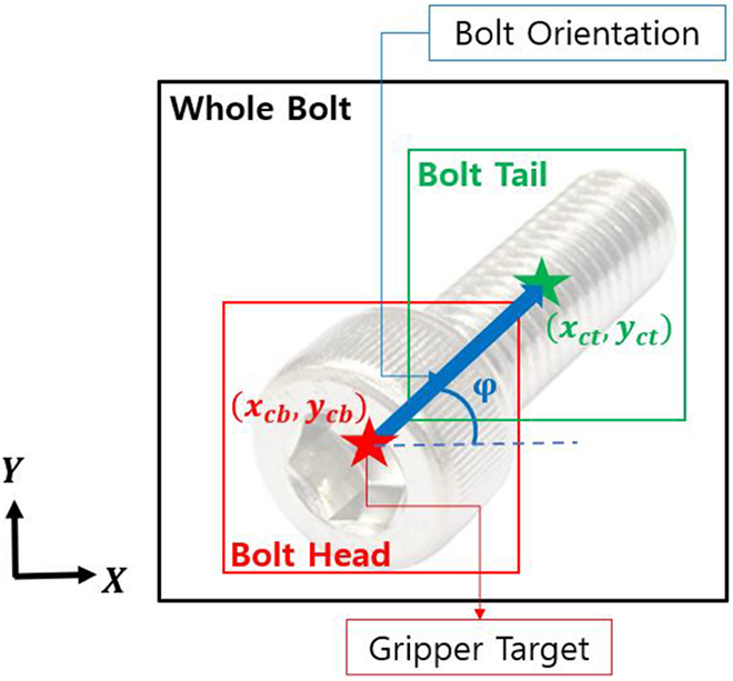
The reason that the number of classes is four is aiming to finding the bolt orientation. To grip the bolt accurately in a robot gripper, information on the orientation is essential, but the YOLOv3 result only informs the center position (x, y), width (w), and height (h) of the object through a bounding box, thus, the orientation of the object is unknown.
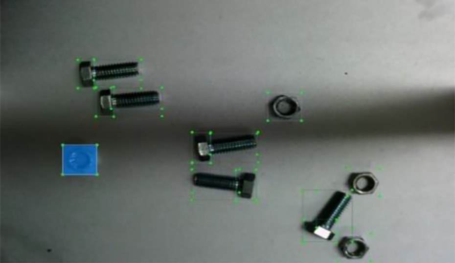
In this work, rather than finding the bolt by YOLOv3, it is divided into three classes: Whole bolt, Bolt head, and Bolt tail. On the other hand, the shape of the nut circular, so one class is enough for nut detection and its geometric information.
In learning, as shown in Figure 3, the bolt head was designated as Bolt head, the screw part as Bolt tail, and the entire bolt as Whole bolt. Unlike general objects, the position and orientation of the bolt are crucial for the robot to pick it up for the following assembly process. The center value of the bolt head is the position at which the robot gripper should move to pick up the bolt, and the orientation of the bolt is necessary for the gripper to pick up the bolt head in the width direction. Here, the orientation can be derived using the vector connecting the bolt tail center and the bolt head center if two bounding boxes of Bolt head and Bolt tail are successfully found through YOLOv3. Lastly, Whole bolt class plays the role in properly matching the bolt head and bolt tail.

Three classes assignment for geometric information of bolt.
When the gripper is placed as shown in Figure 4, the orientation of the gripper can be determined through equations (2) to (4)


Orientation between bolt and gripper.
In this work, a data set for learning was produced by taking 1000 images of bolts and nuts placed randomly on the floor. Therefore, no other objects were put in the learning data, and all of the data set were taken directly with a camera. Thus, six to eight bolts and nuts were included per image, increasing the learning efficiency compared to the number of image data.
YOLO Training
At the first stage, labeling was conducted using YOLOv3 label-master (tzutalin, github). 23 Annotation was created by designating the class and size for each bolt and nut in image as shown in Figure 5. As previously explained, there are four classes in the bolt: Whole bolt, Bolt head, Bolt tail, and one class for the nut.
YOLOv3 labeling work.
In addition, in the actual robot work, a human hand or a robot gripper could enter the work space. Therefore, to recognize only bolts or nuts, a data set including externally intervened objects was used. If the hand or gripper is not labeled within the data set, as shown in Figure 6, YOLOv3 determines it as an object not to detect and thus learns not to create a bounding box.

Learning data sets formation process including hand, gripper, and so on.
After that, data augmentation was performed to secure more input data set. Using the imgaug library (aleju/imgaug), 24 five options were applied: Hue value change, brightness change, contrast, blur, and dropout (Figure 7). Here, hue change was applied in common to other four argumentation. At this time, as shown in Figure 8, the process was repeated for every 100 raw data, and learning time was saved by producing the next data while the previous data were being learned. Finally, the existing 1000 image data set was amplified to 5000 through image augmentation.

Effects of image augmentation: blur, brightness, contrast, and dropout: hue common to all four cases (clockwise from the top left).

Flowchart for data set amplification.

Description of all coordinates for camera calibration.

Image of performing YOLOv3 learning for detecting bolts and nuts.
Experiment setup for checking image coordinates for image distortion correction.
Camera calibration
Next, in order for the robot to accurately pick up the bolt and nut placed on the floor and move it to the designated location, the 2D coordinates (

In equation (5), the values in
Camera calibration 25,26 is the process of obtaining internal and external parameters, and it was obtained using the Camera Calibrator app of MATLAB. The camera is located 400 mm above the floor, and the calibration was repeatedly performed by taking pictures of 13 checkboards. Through the process of substituting and verifying the parameters obtained through the camera calibration, the most appropriate calibration matrix was confirmed by equation (6)

From the obtained calibration matrix, the internal and external parameters were determined as follows


Even after the calibration is done successfully, there is no guarantee that the position and orientation of the detected object with respect to the reference frame is correct because the image captured to the camera is likely to be distorted as long as a cheap camera is employed. In particular, the image of the object far from the plate center is more distorted than the image of object placed at the center of the working plate. Here, to correct the position and orientation of the object associated with the distorted image, the correct position and orientation of the object were obtained using the lens distortion coefficient. 27


where k
1 and k
2 are lens distortion coefficients, which are obtained from internal parameters during the calibration process and are unique values of the lens regardless of resolution.
After applying distortion correction, the value of the object’s center position relative to the image coordinate is converted back to the position relative to the reference coordinate through the correction matrix, which becomes the actual position where the robot can pick up the object. Then, the centers between the bolt head and the bolt tail are used to determine the orientation of the object, and details are described in the next section. Finally, the robot arm uses the detected bolt or nut and its geometric information to accurately pick it up and move it to the target position through the robot’s inverse kinematics.
Experimental results in object detection by YOLOv3 and camera calibration
In the learning process to determine the four classes for the bolt, and one class for the nut, and geometric information of the bolt, 2000 epochs were trained for 6000 bolts and nuts data sets through YOLOv3, and the loss was finally reduced to about 0.03. Normally, in YOLOv3, if the loss is less than 0.06, it is considered that the learning is perfectly done. However, this loss is only for the training data set, so the accuracy of the object detection and its geometric information when the actual image is applied may not be guaranteed. To ensure the performance on detection of bolt and nut and orientation angle of the bolt, experiments were performed directly using the finally learned weight values and the success rate for picking up the bolt and nut was measured. The experiments were divided into three areas: Performance on the detection and geometric information for an object through YOLOv3, image correction, and object pick up and movement test.
Detection performance test
To check whether the proposed learning scheme through YOLOv3 to detect the bolt and nut and determine its geometric information was successful, we tried to check whether bounding boxes were created correctly after detecting the bolt. A total of eight objects (four bolts and four nuts) were randomly placed on the plate and the bounding boxes generated from the image were analyzed (Figure 10).
If detection is performed perfectly, 16 bounding boxes should be created for 8 objects, three per bolt (Whole bolt, Bolt head, and Bolt tail) and one per nut (Nut), respectively. Among these bounding boxes, the accuracy was derived by calculating the number of times the bounding box was incorrectly captured. The four types in which the bounding box may be incorrectly caught are as follows. (a) When an object to be caught is missing (b) When multiple bounding boxes for one object are captured (c) When captured where there is no object (d) When the label is incorrectly classified
Among these, cases (c)and (d) can be solved by creating the test environment similar to the environment of the learning data set. In the actual test, only errors corresponding to cases (a) and (b) appeared.
To obtain the accuracy of detection for each class, the test is repeated 20 times to obtain 320 bounding boxes. After counting the bounding boxes that are detected as missing or duplicate for each class (80 each), the detection accuracy was derived for each class and the results are shown in Table 1.
Detection accuracy according to classes.

All four classes showed an accuracy of 90% or more, and the nut was 100% accurate, which states that all bounding boxes for the nuts were detected perfectly without error. Bolt tail’s accuracy was the lowest at 92.50%. This is associated with the fact that the tail shape does not have relatively distinct feature compared to other classes. Since it plays a crucial role in determining the gripper’s posture for pickup, a more data set learning is required.
Image calibration performance test
In the case of the monocular camera used in this study, the radial distortion occurred, which resulted in the shift of the image outward like a convex lens. Since the detected bounding box coordinates become also inaccurate by image distortion, image distortion should be corrected for the robot to successfully pick up the object.
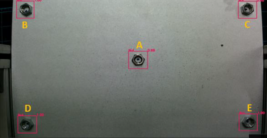
Object detection was done by placing one nut in the center of the working plate, where the distortion is least, and four nuts on the edge, where the radial distortion is the most (Figure 11).
By applying distortion correction (9–10) for the center coordinates of each bounding box of the five nuts (denoted by A, B, C, D, and E) the center coordinates for the bounding boxes are corrected. Table 2 shows the results of distortion correction for the center coordinates of five bounding boxes. As can be seen from this result, the more the object moves away from the center of the image, the greater the distortion occurs. After estimating the center value of the object using YOLOv3, it was transformed into the value with respective to the reference coordinates and then compared with the actual measured value. Table 3 shows the comparison results between the two center values. The resolution of the camera used here is 1280 × 720.
Bounding box center coordinates by image correction (unit: pixel number).

Bonding box center coordinates by YOLOv3 and actual measurement (unit: mm).

Nut A in the center of the image has a zero error, and the remaining four nuts show errors of approximately 1 mm to 4 mm compared to the actual coordinates. Since B, C, D, and E are at the location where the image distortion is most severe, the relatively large error occurs.
Since the width of the gripper used in this work is 20 mm, the maximum error of 4 mm was judged to be within the allowable range for the gripper used, and it was not a big problem in picking the nut. However, since more precise control is required when assembling the actual nut, it is necessary to perform a more rigorous calibration work and distortion correction.
Parts picking test
System configuration
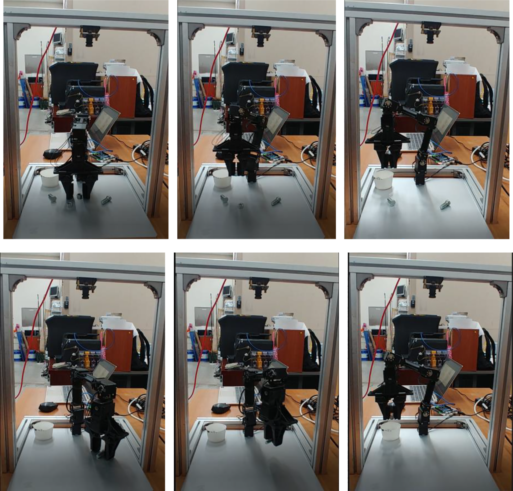
Here, experiments were conducted to confirm the reliability of object detection and its geometric information determination. We checked the whole processes after placing several bolts and nuts on the working plate: detecting the bolt and nut, grasping it with right posture, finally moving it to the designated location.
Figure 12 is the overall work flow of picking up, transferring, and dropping off bolts and nuts after identifying the target. Using the proposed method that divides several parts from one object by creating bounding boxes through YOLOv3 the center and orientation information of each bolt and nut are identified, and these values are transformed relative to the reference coordinates to inform the robot gripper to pick it up. Then, the robot determines the picking order for identified objects, and then the geometrical information on the bolts and nuts and picking order is delivered to the robot arm controller.
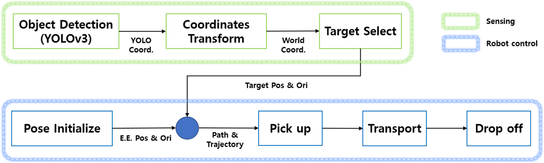
Work flowchart for parts picking.
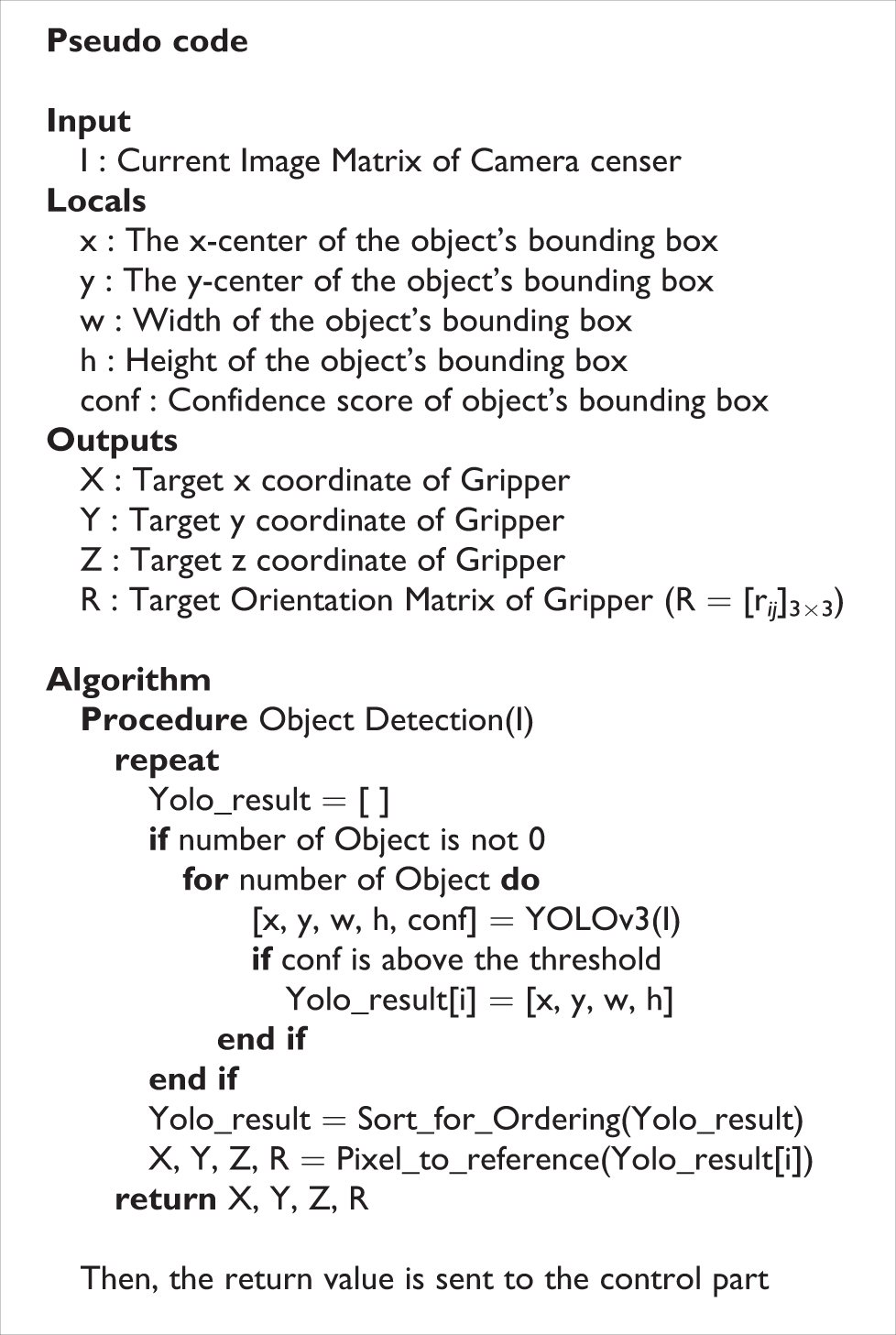
Now, the pseudo code of the whole process is summarized in the following box.
Bolt orientation test
In this part, experiments were conducted to check whether the bolt orientation obtained by the proposed method on object recognition and determination of geometric information was correct. The orientation angle of the bolt

where
Bolt orientation angle determination from separately detected bolt center and tail center by YOLOv3.
Then, the orientation angle was compared with the directly measured angle. Figure 14 shows the bounding boxes of bolt head and tail for each bolt and the corresponding orientation angles for the bolts. Table 4 shows the comparison between the determined orientation angles of five bolts and the measured angles.

Bounding boxes of head and tail for each bolt and the corresponding orientation angles for each bolt.
Comparison between bolts orientations by YOLO and actual measurement (unit: degree).

In this experiment, an insignificant orientation angle error of 0.3 or less was found for all five bolts. To increase the reliability of the method for determining the bolt posture, six additional experiments were conducted. Table 5 shows the results, similar to Table 4, and it can be seen that the average errors are less than 0.6° for all bolts.
Bolt angle errors for six trials (unit: degrees).

Picking test
After placing two bolts and two nuts in the work space, the robot is controlled to pick them up and move them to specific positions one by one. Figure 15 shows the entire picking process when performing the task. Figure 16 shows that even with the gripper and human hand moving in the workspace during the operation, the bounding boxes are captured only for bolts and nuts on the plate by training the data set shown in Figure 6. It can be confirmed that object recognition of bolts and nuts proceeds smoothly even if such external intervention occurs.
Execution process of picking bolt and nut (top: nut, bottom: bolt, video supplemented).
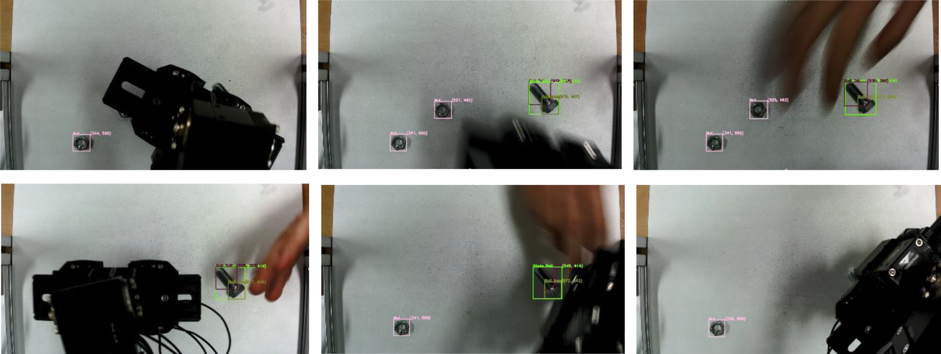
Bounding boxes generation overcoming hand and gripper intervention.
Repeated picking task test
Table 6 summarizes the results of picking task for 20 times, 50 times, and 100 times each for bolt and nut, respectively.
Picking task success rate for bolts and nuts.
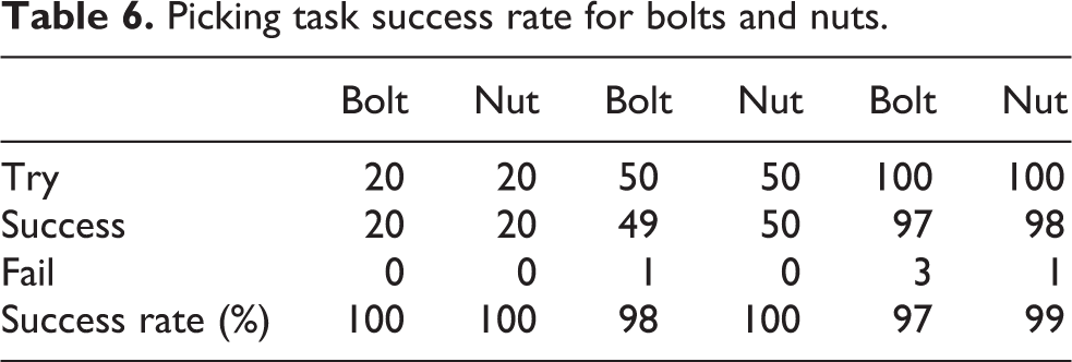
As a result of the tests, it was confirmed that the picking and subsequent transporting of the target object were performed very well. There was no significant difference in the success rate when picking bolts and nuts repeatedly 20 times, 50 times, and 100 times in the picking experiments. However, in the case of repeating 100 times, there were three times of bolt-gripping failures. Some failures belong to the second case described in section “Image calibration performance test,” which was caused by an incorrect postural command because two bounding boxes for one bolt tail were caught for one bolt, and this can be resolved by more appropriately adjusting the YOLO v3’s NMS value. Another failure factor is the fourth case described in section “Image calibration performance test,” where the bolt head and tail are recognized as the same class. In other words, when the surrounding environment changes, the tail of the bolt is not recognized correctly, and the three bounding boxes are not clearly distinguished. This can be overcome by properly adjusting the threshold value of each corresponding bounding box.
Performance comparison with general YOLOv3 based on COCO data set
The performance of the proposed YOLOv3-based object detection process was compared with YOLOv3 (named Original) performed on the basis of the existing COCO data set. For mAP, the original referenced the results of YOLOv3-416 shown in Levine et al., 17 and the performance results of this study were obtained from the detection rate shown in Table 7. Frame per second (FPS) was set as the average value directly measured for 1 min.
Performance comparison with YOLOv3 based on COCO data set.
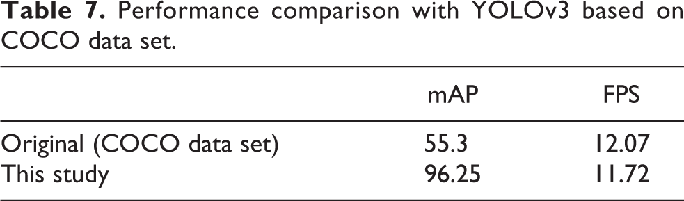
The mAP was 96.25, which was significantly improved compared to the original case of 55.3. It is regarded as a result of learning by applying various image options in a limited workspace. For the actual application process, the goal was to achieve mAP of 90 or higher, and although it is not perfect, it is understood that it has reached a sufficiently applicable value.
In the case of FPS, it was reported as 34.48 in the original case, but in the actual execution, it was shown to be 12.07. This seems to be a difference due to computing power. The FPS of this study was measured to be 11.72, which was similar to the previous value.
As a result, this study succeeded in achieving sufficient mAP at a level that can be applied to the process while acquiring object orientation information that was previously impossible through YOLOv3 without reducing FPS.
Conclusions
In this work, an automatic bolt and nut-picking system that recognizes bolts and nuts and extracts geometric information at the same time by applying YOLOv3 architecture was introduced, and the effectiveness of this system was confirmed through actual tasks. In the case of bolt, by creating multiple bounding boxes for one bolt, the picking position was accurately determined by the center of the bolt head, and a vector connecting the two centers of the bounding boxes of the bolt head and bolt tail was found to determine the posture to pick up the bolt. Also, even if an object other than the target object intervened in the middle of object recognition, only the target object was detected by excluding the intervened objects in the training process. As a result, using a basic YOLOv3 architecture, it was confirmed that automatic pickup of target object from bolts and nuts randomly placed on the plate can be achieved with sophisticated object detection algorithm and its geometric information extraction.
In this work, since object detection was performed with a low-cost monocular camera, the center value of the bounding box was different from the actual value due to the camera distortion. To solve this problem, the image correction is performed to find the correct object center and then send the information to the robot controller. Due to the limitation of the monocular camera, automatic picking was performed only for bolts and nuts placed on the flat working plate, which has the fixed Z axis value. By further expanding the work, it is expected to be able to perform automatic pickup of objects on a curved surface by introducing stereovision using a binocular camera system or an additional distance measurement sensor.
On the other hand, deep learning algorithm is advancing very rapidly, and the YOLO model applied to this system has been upgraded from YOLOv3 to a higher version such as YOLOv4 and YOLOv5. If the latest high-performance YOLO model for object detection along with appropriate sensors is employed, it is expected that an automatically picking a target arbitrary placed on 3D surface with higher reliability can be developed.
Footnotes
Declaration of conflicting interests
The author(s) declared no potential conflicts of interest with respect to the research, authorship, and/or publication of this article.
Funding
The author(s) disclosed receipt of the following financial support for the research, authorship, and/or publication of this article: This research was supported by Korea Institute for Advancement of Technology (KIAT) grant funded by the Korea Government(MOTIE) (P0008473, HRD Program for Industrial Innovation).
Supplemental material
Supplemental material for this article is available online.
References
Supplementary Material
Please find the following supplemental material available below.
For Open Access articles published under a Creative Commons License, all supplemental material carries the same license as the article it is associated with.
For non-Open Access articles published, all supplemental material carries a non-exclusive license, and permission requests for re-use of supplemental material or any part of supplemental material shall be sent directly to the copyright owner as specified in the copyright notice associated with the article.