
Abstract
The friction stir welding robot for aerospace applications developed by the research group is subject to the effects of size, working conditions, and other conditions during the operation. The load conditions of the friction stir welding robot are harsh, and the strength and stiffness tests of the whole machine need to be carried out. Five typical working conditions of the friction stir welding robot are analyzed. By analyzing the system composition and configuration of the robot, the loading conditions of the robot stirring head during the welding process are accurately simulated, and this is used as the stiffness and strength check. The boundary conditions of the robot are simulated and analyzed under typical working conditions. The results show that the data of each part of the robot under load are obtained for a given size of the rocket cap welding. After analysis, the maximum normal displacement of the friction stir welding robot reached 0.6424 mm and the maximum stress was 79.21 MPa under the condition of melon flap welding.
Keywords
Introduction
At present, in the fields of China’s aerospace, military, and national defense, many large thin-walled parts have to be welded in sections (shards) due to their large size and complex structure, such as fuel tanks for heavy-duty rocket (CZ-5) engines, the skin structure of large aircraft (C919), and the intake duct of the new generation fighter (J-10). Due to the reduced weight and improved fuel efficiency, aluminum alloys are increasingly used in the automotive and aerospace industries. 1 These structural parts are generally welded with 2XXX and 7XXX aerospace aluminum alloys that are not suitable for traditional fusion welding methods. 2
Friction stir welding (FSW) is considered to be the most important discovery in the field of metal connection in the past two decades. FSW has many advantages when welding lightweight alloys. 3 The welding process does not require welding wire, does not require shielding gas, and does not generate arc light and spatter, especially the welding seam has excellent mechanical characteristics and is favored by the welding field. It has been widely used in high-strength aluminum alloy welding in the aerospace field. 4 –8
Around the world, ESAB of the United Kingdom, NASA of the United States, Hitachi of Japan, Airbus of France, Bombardier of Canada, Shanghai Aerospace Equipment Manufacturing Plant of China, and Beijing Safest have developed corresponding mixing friction welding equipment. 9 –12 Scholars from all over the world have also studied FSW equipment. Salari et al. studied the influence of FSW process parameters on the microstructure evolution and mechanical properties of 5456 aluminum alloy sheet under different thickness and tempering conditions. 13 Sekban et al. studied the impact toughness of friction stir processed low carbon steel. 14 Khodabakhshi et al. studied the residual stress in the bonding process of FSW surface. 15 Zhou et al. studied the effect of tool speed on the microstructure and mechanical properties of Al-Mg-Si alloy FSW joints. 16 Aktarer et al. studied the microstructure, mechanical properties, and biaxial tensile forming properties of friction stir welded part. 17
Some scholars have studied the body of FSW robot. De Backer et al. studied the path compensation method of FSW robot. 18 Mejri et al. analyzed some dynamic characteristics and mechanical properties of machining robots. 19
For large and complex thin-walled surfaces in the industrial fields such as aerospace, rail transportation, and ship electronics, the types of welds are diverse and their distribution is complex. 20 –22 Although the use of industrial robots as the welding body can meet the needs of process flexibility, due to the process characteristics of FSW, compared with the cutting and drilling loads of traditional machining, its load state is not only complicated but also more severe, which seriously affects the welding quality of seam forming. 23,24 At present, the research of FSW is mostly focused on obtaining better welding results by changing some parameters of the equipment, but there is not much research about analysis of load and strength stiffness of FSW equipment.
This article introduces in detail an FSW robot specially developed by the research group in the aerospace field, including system structure composition, degree of freedom configuration, compensation principle, spindle system design, and five typical working conditions. The loading conditions of the robotic stirring head during the welding process were accurately simulated, and the boundary conditions of the stiffness and strength check were used as the boundary conditions for the robot to perform simulation analysis under the condition of melon flap welding. The results show that the newly developed FSW robot is capable of welding large and complex space curved surfaces, and its own process performance is good, which provides a practical solution for achieving high-precision welding in the aerospace field.
The system structure of FSW robot
Large thin-walled curved surface FSW robots are mainly composed of two major systems, namely the robot body system and the turntable system, as shown in Figure 1. The two systems are independent of each other in mechanical structure and communicate with each other in information and control. Among them, the robot body is a seven-degree-of-freedom configuration, including the translational freedom of the first three joints (XYZ axis), the rotational freedom of the two joints at the end (AB axis), and the two freedoms of the feed axis and rotation axis of the stirring head degree. The turntable has a degree of freedom of rotation and can be rotated 360° in the forward and reverse directions.

FSW robot large-scale thin-wall surface structures. FSW: friction stir welding.
The robot body has a weight of about 72 tons, and the outer dimensions are about 4.2 × 2.8 × 3.6 m3 (length × width × height). The XYZ axis is mainly composed of a large support, a guide mechanism, a transmission mechanism, a gravity compensation mechanism, and a center of mass compensation mechanism. Among them, the supporting large parts include the bed, the column, the saddle, and the ram, which are the bases for the connection, fixation, and movement of other components; the guide mechanism mainly adopts the form of rolling guides to achieve the function of motion guidance, including linear guides, sliders. As well as the fixing device, these parts largely determine the overall rigidity and welding accuracy of the robot. The transmission mechanism mainly adopts ball screw transmission, including the screw nut pair and the support and drive structure at both ends. They mainly provide power transmission and precision positioning. A-B shaft is mainly composed of A-axis support, B-axis support, A-axis transmission, and B-axis transmission. Among them, the transmission of the A-B shaft is driven by double worm gears to meet the requirements of precision of FSW and severe load. The turntable system has indexing, positioning, and locking functions, and the table size is 3.5 m, which can ensure the welding of large rocket barrels and top covers. Its composition structure mainly includes support structure, guide mechanism, and transmission mechanism. The working space and main kinematic performance indexes of the FSW robot are shown in Tables 1 and 2.
The workplace of the FSW robot.

FSW: friction stir welding.
Movement indicators of the FSW robot.

FSW: friction stir welding.
However, the Z-axis(ram) of the FSW robot is a cantilever beam configuration, which the length of the cantilever is time-varying (depending on the position of the welding point). When the Z-axis is extended, its center of gravity gradually moves away from the Y-axis, and the deflection torque generated relative to the X-axis also gradually increases (due to the effect of its own weight). At the same time, the motion characteristics of the Z-axis will also be affected by the end-load change of direction. The combined effect of these factors will have a great impact on the deformation and stability of the robot and bring great challenges to the design of the high-quality control system of the robot. To solve the above application requirements, a gravity compensation mechanism and a centroid compensation mechanism are designed. The introduction of these two compensation mechanisms guarantees the welding accuracy and stability of the heavy-duty FSW robot.
The gravity compensation mechanism is mainly used for compensating the driving torque of the Y-axis motor. The wire rope is used to suspend lead blocks to offset the gravity of the Z-axis system components (mainly large saddles and large rams). The entire compensation mechanism is divided into two sets of the same mechanism on the left and right and is installed on the top of the Y-axis column through a pulley set. The steel wire rope passes around the pulley block, and its two ends are respectively connected to the saddle and the lead block. The weight of a single lead block is 3 tons, which is suspended in the vertical guide groove of the Y-axis column assembly, and moves up and down with the movement of the Y-axis.
The center of mass compensation mechanism is mainly used to compensate for the eccentricity problem when the Z-axis ram is extended, so that the end of the tool of the stirring head and the workpiece to be welded always maintain a certain position. The compensation mechanism adopts the “lever principle.” The lever arm is driven by a screw lifter. The lever arm drives the spline shaft to rotate, and the spline shaft drives the saddle to receive torque opposite to gravity. “Head down” problem. The magnitude of the compensation torque depends on the distance of the ram. The pressure sensor between the saddle and the column can be calibrated to obtain the relationship between the compensation torque and the length of the ram overhang.
The main shaft system of the FSW robot performs the telescopic movement and the rotary movement of the stirring head. The telescopic movement controls the insertion force and depth of the mixing head, and its principle is similar to that of the turbine worm drive. The spindle system is equipped with a feed motor, which is equipped with gear at the end. When the feed motor rotates, it drives the gear to rotate. The gear is connected to the spindle through threads. When the gear rotates, it can drive the spindle to complete the telescopic movement. Rotary motion is responsible for adjusting the speed, which is directly dependent on the drive motor of the spindle. The structural design of the FSW robot spindle system is shown in Figure 2.

Structure design of FSW robot spindle system. FSW: friction stir welding.
Five typical working conditions of the FSW robot
Taking the connection of the low-temperature fuel tank and the large arch structure of the rocket as an example, as shown in Figure 3, it needs to assemble and weld multiple melon petal-shaped panels. The thickness and radius of curvature of these panels vary along the length of the weld. According to the robot’s welding task classification, it can be summarized into five typical welding conditions, respectively, the melon flap welding condition, the melon top circular seam welding condition, the melon bottom circular seam welding condition, the cylindrical longitudinal seam welding condition, and the cylindrical ring seam welding.

Structural composition of the rocket head and body.
In view of the above five typical working conditions, the specific welding conditions of the large arched structure of the low-temperature fuel tank and the rocket are introduced as follows: Melon petal welding: During the welding process, the bottom turntable will be locked. The Y-axis, Z-axis, and pitch joints will be used to move the welding head along the weld and in the appropriate direction. The preferred welding direction is from the outer diameter to the inner diameter. The welding description is shown in Figure 4. Melon top ring seam welding: When assembling large arched structures of low-temperature fuel tanks and rockets, it is often necessary to weld the dome to the complete arched structure. During welding, the welding head remains stationary and the bottom turntable is used to move the weld. The welding direction can be clockwise or counterclockwise. Melon bottom ring seam welding: When assembling large arched structures of low-temperature fuel tanks and rockets, it is often necessary to weld the arched structural components to the ring. During welding, the welding head remains stationary and the rotary disk is used to rotate the position of the weld. Its welding direction can be clockwise or counterclockwise. Cylindrical ring seam welding: When assembling large rockets, multiple cylinders need to be welded into one body and welded along its circumference or orbit. During the welding process, the welding head is always aligned with the Z-axis and the bottom turntable is used to rotate the weld. The welding direction can be clockwise or counterclockwise. Cylindrical longitudinal seam welding: When assembling large arched structures of low-temperature fuel tanks and rockets, multiple cylinder plates need to be welded into cylinders. During the welding process, the rotary disk at the bottom remains stationary and the welding head will move along the Z-axis. The welding process takes place in the vertical direction.

Melon petal welding condition of FSW robot. FSW: friction stir welding.
With the combination of the above five typical working conditions, welding of the tank for the storage of fuel and oxidant of the launch vehicle, the arrow body of the launch vehicle, the rocket dome structure, the intake and exhaust holes of the jet aircraft, and the wing structure and flaps of the jet aircraft can be welded. The linkage of each joint during the FSW robot’s execution of the above five typical working conditions is shown in Table 3.
Working mode and linkage situation of motion axes under five typical working conditions.

Load analysis of FSW robot
In the five typical working conditions, there is only one motion axis when FSW robot under the four working conditions of vertical seam welding on the top of the melon, circular seam welding on the bottom of the melon, circular seam welding on the cylinder, and longitudinal seam welding on the cylinder. When the robot performs petal welding, its Y-, Z- and A-axis are all motion axes. The petal welding working condition is the most complex and difficult one among the five typical working conditions of the robot. It is the most reasonable and effective one to combine the working condition of the petal welding in the load analysis of the robot.
Load analysis of FSW process
FSW is a welding method that the welding head with shoulder and stir tool. First, welding head is rotating at high speed and inserting into the seams of the welding workpieces, making the workpiece material in the area of contact with the shaft shoulder and stir tool subjected to friction and plastic deformation and then heat generating and soft. Finally, the workpiece material in the plastic state completes the whole process of solid-phase welding seam connection by the effect of stir head spins, 25 its welding principle as shown in Figure 5.

Principle of FSW. FSW: friction stir welding.
FSW can be divided into the following four stages: first, under the action of axial force, the stirring head will be mechanically inserted into the welding workpiece joints. Then, under the action of torque, the stirring head starts to rotate and cause friction with the welded part, making the material temperature of the welding joint rise and plasticize. Thirdly, when the welding head reaches the predetermined depth, it stops inserting and starts moving along the welding line of the workpiece under the action of feed force. Finally, due to the rotation and movement of the stirring tool, highly plastic materials are constantly stirred from one end of the workpiece to the other end, and under the action of the forging force of the stirring head and shaft shoulder, dense welding seams are formed behind the moving direction.
The force model of the mixing head
During the whole welding process, the stress state of the mixing head can be divided into two working conditions: insertion working condition and moving working condition. In each working condition, the load on the mixing head includes the action of positive pressure and friction, as shown in Figure 6. Among them, the positive pressure mainly comes from the contact and extrusion between the welding material and the outer surface of the stirring needle and the shoulder surface of the shaft, which is finally combined into the resistance along each axis direction, such as insert resistance and feed resistance. The friction force comes from the high-speed rotation of the stirring head, which is finally equivalent to the resistance moment of the welding process of the stirring head, such as the rotary torque. 26

Force analysis of FSW head: (a) insert resistance and (b) feed resistance and resistance torque. FSW: friction stir welding.
It is assumed that the material of the welded parts is uniform, and the stirring head is always perpendicular to the plate during the welding process. Then, the insertion resistance of the stirring head under the insertion condition mainly includes the positive pressure on the bottom of the stirring needle, the vertical component of the positive pressure on the side of the stirring needle, and the positive pressure on the end face of the shaft shoulder of the stirring head, as shown in Figure 6(a).
The positive pressure exerted on the bottom surface of the stirring needle and the shoulder face of the shaft generates positive insertion resistance along the Z-axis
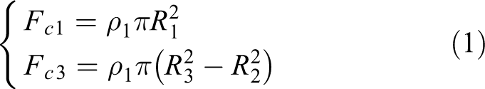
where
The positive pressure on the side of the stirring needle is decomposed in the vertical direction to generate the insertion resistance of the other part, which is in the positive direction along the Z-axis

where
Rotating torque is generated by friction between the stirring head and the workpiece due to the rotation of the stirring needle base and the shaft shoulder surface, as shown in Figure 6(b)

where
The friction force on the side of the stirring needle is decomposed into the negative rotating torque along the Z-axis of the stirring head

where
In the running condition, because the highly plastic material continuously flows to the back of the moving direction of the stirring needle, only the front half of the stirring needle is subjected to the positive pressure and friction of the material. However, the bottom surface of the stirring needle and the end face of the shaft shoulder will still bear the action of positive pressure and friction, which are equivalent to the insertion resistance and rotation torque of the stirring head, respectively. The expression is similar to the insertion condition, and it will not be repeated here.
The positive pressure on the front part of the side of the stirring needle can be decomposed into a part of the insertion resistance and a part of the feed resistance of the stirring head. The insertion resistance caused by the positive pressure on the front half of the stirring needle is

where
The feed resistance caused by the positive pressure on the front half of the stirring needle is

The friction force on the front side of the stirring needle can be divided into a part of transverse resistance and a part of rotating torque. Lateral resistance caused by the friction on the front half of the stirring needle is

where
The rotation torque caused by the friction on the front half of the stirring needle is

In this way, all the loads of the mixing head in the insertion condition and the moving condition can be simply summed up.
Numerical simulation of welding process
The three-dimensional (3D) solid model of the stirring head and welding parts was established in the 3D rectangular coordinate system with the application of DEFORM-3D version software, and the arbitrary lagrangian-eulerian (ALE) finite element method and the dynamic mesh deformation technology were used. Since the area where the material flows is mainly located near the welding seam, the mesh around the mixing head should be thinner, while the one far away from the welding seam should be thicker, so as to give consideration to the accuracy and speed of solution.
The finite element model of the welding process is shown in Figure 7(a), wherein the material of the welded workpiece is aluminum alloy 7075, and the material of the mixing head is alloy steel. Using Hypermesh software, mesh is divided and material property parameters are assigned. The model is then imported into the DEFORM-3D software to define boundary conditions and analyze settings. After setting the mixing head’s insertion speed, feed speed, and rotation speed, the simulation calculation was carried out, and a total of 5.8 s (121 steps) of the welding process is simulated. The whole welding process, temperature field distribution of cutting section in welding zone is as shown in Figure 7(b), you can see the weld area of the maximum temperature reached 447°, the temperature field in nabla shape.
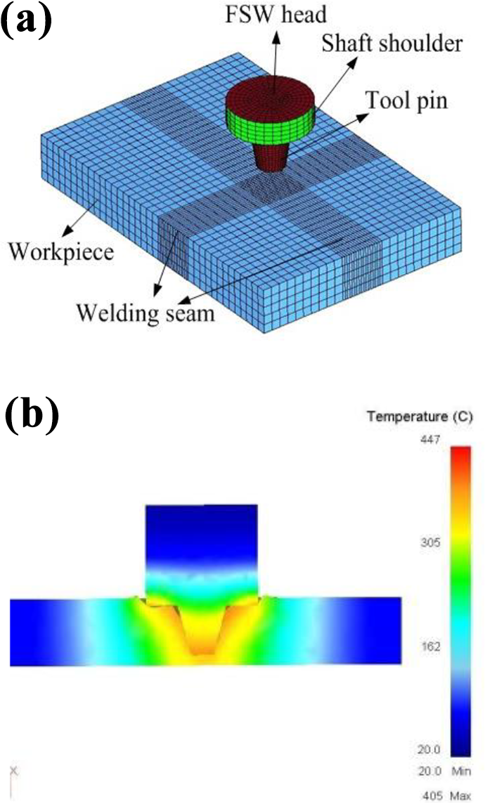
Numerical simulation of FSW process: (a) FEM mesh model and (b) temperature field of stir zone. FSW: friction stir welding; FEM: finite element method.
In addition, to obtain the load input of FSW robot under typical working conditions, various load data curves of the stirring head during the whole welding process were measured, as shown in Figure 8. Under different welding conditions, each load data curve is different, and the mechanical boundary conditions of FSW robot in each typical working condition can be taken as the input reference according to the data of load peaks in the whole welding process.

Simulation results curves: (a) insert resistance and feed resistance and (b) rotation torque.
In the mixing head insertion condition (0–4 s), with the continuous increase of the insertion depth, the insertion resistance and the rotation torque gradually increase from zero, while the feed resistance is always zero, which is the reason that the mixing head has not moved along the weld under this condition, so the feed direction is not stressed. According to the measurement, the maximum insertion resistance of the stirring head and the maximum rotational torque are 3652 N and 261 Nm, respectively, under the insertion condition.
In the running condition of the mixing head (4–5.8 s), it can be seen from the figure that the load data tend to be stable, and the insertion resistance is reduced and stabilized at 243 Nm. This is for the fact that during the insertion stay, the welding material softened due to the increase of temperature, and then the insertion resistance decreased. With the advance of the mixing head, the material in front is still in a cooling state, and the insertion resistance is further increased. However, the feed resistance is affected by the movement of the stirring head along the weld, and the load rapidly increases from zero and gradually stabilized to 1226 N. Among them, the variation range of rotary torque is very small, basically stable around 240 Nm.
Working condition simulation of FSW robot
The stiffness of the robot is an important dynamic parameter. The stiffness of the whole machine is the main factor affecting its dynamic characteristics and positioning accuracy. For FSW robot, the rigidity of the machine is very important to the welding precision. In the process of robot welding, stirring pin shoulder should always keep uniform contact with the workpiece to be welded, so as to ensure that the welding seam can meet the given error range after completion of welding. Therefore, the welding accuracy of FSW robot mainly depends on the displacement change of the shoulder face of the stirring pin. By selecting the welding configuration of FSW robot under five typical working conditions and using the load boundary conditions of the mixing head in the numerical simulation process, the displacement of the shoulder face of the stirring pin shaft along the coordinate system in each direction and the change of the combined displacement are calculated respectively. In this way, the stiffness of the configuration of FSW robot under different welding conditions can be quantitatively evaluated through analysis and comparison.
Load and boundary conditions
This article takes petal welding as an example to illustrate the stiffness analysis of FSW robot. According to the characteristics of the task, the worst configuration of the robot occurred at the end of the welding process. At this time, since the robot’s sliding pillow has the longest extension, the static deformation at the end of the mixing head is the largest under the action of gravity. Figure 9(a) shows the load and boundary conditions borne by the FSW robot under the condition of pedicle welding. On this basis, the connection between the parts is established and the material properties of the parts are given. The internal components of FSW robot are mainly composed of alloy steel and gray cast iron. The finite element model after pretreatment is shown in Figure 9(b).

Finite element analysis of melon-disc condition: (a) load and boundary condition and (b) FEM mesh model of FSW robot. FSW: friction stir welding; FEM: finite element method.
The base and foundation of the robot are completely fixed by bolt connection. The insertion resistance, feed resistance, and rotary torque during the welding process all act on the shaft shoulder position of the stirring needle. The forward traction force (compensation force) generated by the gravity compensation mechanism produced through the wire rope acts on the upper end of the sliding saddle, and the reaction force of the wire rope acts on the upper end of the column through two pulley groups. In addition, the robot is subject to gravity. All external load data of FSW robot in peel-welding condition are shown in Table 4.
All of the load of melon-disc condition.

Stiffness and strength of the machine
To comprehensively evaluate the stiffness of FSW robot under different operating modes, the stiffness analysis under five typical working conditions was carried out. Figure 10(a) and (b) shows the cloud chart of stiffness and strength of the whole machine under the condition of petal welding. Since the welding precision of the welding seam depends on the displacement change of the shoulder face of the stirring pin along the axis of the stirring head, it is necessary to project the combined displacement analysis data of the whole machine to the direction of the axis of the stirring head for the evaluation of the stiffness of the robot in this working condition. By measuring the displacement data on the shoulder face of the stirring pin, the stiffness of the machine under this welding condition can be obtained.

Stiffness and strength of FSW robot under melon-disc condition: (a) the whole machine stiffness and (b) the whole machine strength. FSW: friction stir welding.
The stiffness data of FSW robot under five typical working conditions are shown in Table 5. It can be found that in the first three typical working conditions, the deformation of the stirring pin shoulder surface is small and slightly different due to the shorter extension of the sliding pillow of the robot and the different force directions of the stirring pin under different welding conditions. In general, the stiffness of the machine under the first three typical working conditions is relatively good. Among them, the best working condition is the circular seam welding condition at the bottom of the melon. Under this working condition, the normal displacement of the shoulder face of the stirring pin shaft is 0.0043 mm. Similarly, in the last two typical working conditions, due to the long protrusion of the sliding pillow, the rigidity of the machine is poor. The operating condition with the worst rigidity of the whole machine was petal welding. The normal displacement of the shoulder face of the stirring pin shaft reached 0.6424 mm.
Displacement of stir pin shoulder end under five kinds of typical conditions.

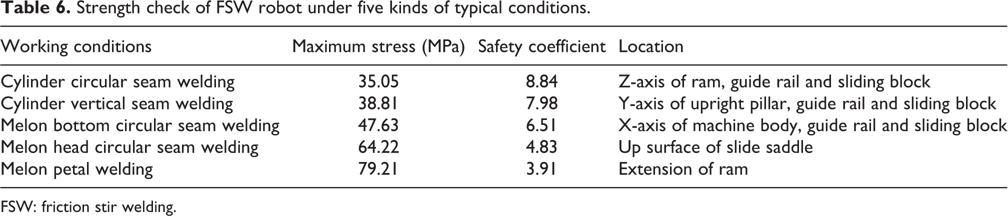
The strength of FSW robot under different welding conditions is shown in Table 6. As can be seen from the data on the table, the strength of the whole machine can meet the design requirements. Among them, the maximum stress of the whole machine is 79.21 MPa under the condition of petal welding of the worst configuration, and the maximum stress occurs at the overhang of the sliding pillow, and the minimum safety factor is 3.91.
Strength check of FSW robot under five kinds of typical conditions.
FSW: friction stir welding.
Conclusion
In response to welding requirements in aerospace, a new type of heavy-duty high-precision FSW robot is introduced. By decomposing its task profile, five typical working conditions of the robot are summarized.
The working principle of FSW is elaborated, and the force model of the stirring head is deduced and verified by simulation. Through theoretical derivation and numerical simulation, we have a deeper understanding of the entire welding process, and the obtained load data have practical reference significance.
Based on the load data curve of the numerical simulation of the stirring head, the load boundary conditions of the robot under five typical working conditions are obtained. Finally, through the numerical simulation of the complete working condition, the stiffness and strength data of the FSW robot under each typical working condition were obtained. The results show that the strength and stiffness of the FSW robot designed meet the actual requirements.
This article discusses the welding operation of the FSW robot from a practical point of view. However, subject to the actual conditions, no experimental research has been carried out on the whole machine. According to the current views, the study of the material flow in the FSW process will also be helpful to the design of the FSW robot. Next, the research on the modified FSW robot should be extended to the experimental stage and the material flow in the welding process.
Footnotes
Declaration of conflicting interests
The author(s) declared no potential conflicts of interest with respect to the research, authorship, and/or publication of this article.
Funding
The author(s) disclosed receipt of the following financial support for the research, authorship, and/or publication of this article: This research was supported by the National Natural Science Foundation of China (Grant Nos 51505470 and 51975567), Natural Science Foundation of Liaoning Province (Grant No. 2019-MS-347), State Key Laboratory of Robotics, SIA, CAS (Grant No. Y7A1207301), Youth Innovation Promotion Association, CAS (Grant No. 2018237), and “JXS” Innovation Fund, SIA (Grant No. 20180504).