
Abstract
The mechanical configuration, structural composition, and five typical working conditions of a newly developed friction stir welding robot are introduced. The kinematics model of the friction stir welding robot is established and the forward kinematics equations, inverse kinematics equations, and the Jacobian matrix are solved. In addition, the dynamics model of the friction stir welding robot is also built by using the Lagrange method. The centroid position coordinate and inertia matrix of each part are obtained. Finally, the dynamic equation of friction stir welding robot is determined. According to the kinematics and dynamics model of robots, simulation analysis for friction stir welding robot based on virtual prototyping technology was carried out. The trajectory equation of the weld joint under the condition of melon petal welding is established, the spline trajectory is fitted by many discrete points measured by the contact probe, and the trajectory planning of each joint and the changing laws of motion parameters under the friction stir welding robot melon petal welding condition are obtained. The movement laws and the loading conditions of each joint can be better controlled by designers, and provide solid theoretical support for the static and dynamic characteristics analysis and structural optimization of the friction stir welding robot.
Introduction
Friction stir welding (FSW) is widely used in aerospace as a solid phase joining technology. Traditional fusion welding process is prone to welding defects such as welding thermal cracks, inclusions, pores, and so on. Compared with fusion welding, FSW has the advantages of solid-state connection, green pollution-free, and excellent joint performance in the aluminum alloy welding process.1–3 Therefore, multibody system FSW robot (FSWR) has also become a research hotspot.
Since the 1960s, the theory of multibody systems has been an important mean to study complex mechanical systems or mathematical model. A large number of scholars have carried out related research work in this field. The research contents cover engineering machinery, industrial robots, rail vehicles, medical equipment, and so on.4–7 The research of multibody system theory mainly includes two aspects. They are kinematics and dynamics respectively.
In kinematics, it mainly studies the mechanism degree of freedom (DOF), trajectory planning, the accessibility and dexterity of workspace, and the change law of motion parameters with time. The dynamics mainly study the transitive relation of load between the end tool space and the joint space, and finally obtain the forces and moments applied on each joint and end-effector. Through the kinematics and dynamics analysis of multibody systems, the motion performance and load-carrying capacity of complex mechanical systems can be reasonably evaluated, which effectively guides the mechanical design work. 8
In this article, the structural composition, application, and main design parameters of one new-type large heavy-load and high-precision FSWR are described first. On this basis, the welding process of FSWR and the function of each component are introduced in detail under special five typical working conditions. By means of the mechanical configuration analysis, the DOF configuration and functional description of each component of FSWR can be expressed explicitly. In order to make the designed robots meet the technical specifications of the actual welding requirements, the kinematics and dynamics of FSWR should be analyzed.9–11 This work mainly includes the solutions of kinematics, dynamics, and the Jacobian matrix.12,13 Among them, the forward kinematics solution determines the position and posture of the robot from joint space to end tool space, and the inverse kinematics solution is the opposite, its goal is corresponding trajectory planning. At the same time, the Jacobian matrix is the bridge of transformation between these two coordinate spaces. The kinematics model can obtain the load change law of each joint, which is used to evaluate the driving performance of the FSWR, thus contribute to the components (motors, reducer, bearing, etc.) selection and robot design work.14–16 Finally, the kinematics and dynamics modeling and simulation of the FSWR provide the theoretical support and feasibility of the design stage and lay a solid foundation for the successful development of FSWR.
The FSWR to be studied
Structural composition of FSWR
The newly developed FSWR is mainly composed of two components: welding body and turntable, as shown in Figure 1. The welding body of the robot is mainly composed of three parts: X-Y-Z axis, A-B axis, and FSW head. The X-Y-Z axis includes the transmission system composed of a ball screw and a linear guide rail, the gravity compensation system composed of steel wire rope counterweight, and the suspension compensation mechanism designed using the lever principle. The A-B axis includes the turbine-worm drive system and the robot spindle assembly section. The turntable is the C-axis of the robot system. The turntable has a DOF of rotation. The workpiece is fixed to the table of the turntable by a special tooling fixture. The turntable has indexing, positioning, and locking functions to meet the welding requirements under different welding conditions. The whole robot has 7 DOFs, includes 3 DOFs of the X-Y-Z axis, 2 DOFs of the A-B axis, and 2 DOFs of the telescope and rotation of the FSW head. The rotational DOF of the FSW tool has no effect on its kinematics model.

Friction stir welding robot (FSWR): (a) composition of the robot and (b) suspension compensation mechanism.
In order to ensure the rigidity of the FSWR, the large structure such as bed, upright pillar, and slip saddle are mainly cast with gray cast iron, and the main bearing structure such as sliding pillar is welded by alloy steel because of its cantilever configuration. Except the turntable, the mass of the robot body is about 71 tons, and the size of the whole machine is about 4.2 × 1.6 × 3.8 m.
The gravity compensation system is mainly used to balance the load of FSWR in the Y-axis direction. The counterweight block is used to balance the weight of the sliding saddle and sliding pillar. The whole balance system consists of two sets of pulley sets and steel wire rope counterweight blocks. Each block is about 3 tons, connected by steel wire rope and suspended in the guide groove on both sides of upright pillar, and the other end of the wire rope is connected to the upper end surface of the sliding saddle. When the Y-axis component of the robot moves up and down, the two counterweight blocks also move up and down in the guide groove, thus reduce the driving burden of the Y-axis motor.
The suspension compensation mechanism is mainly used to compensate the “bow” phenomenon of sliding pillar caused by gravity. 17 The suspension compensation mechanism has two sets of the same mechanism, respectively installed on both sides of the sliding saddle. It is mainly composed of screw lift, support box, rail slider, pressure sensor, lever arm, and spline shaft. It works by driving screw lift to act force onto the lever arm, and then the spline shaft twists sliding saddle. Finally, the sliding saddle drives the sliding pillar to resist the static deformation due to gravity field.
Five typical conditions of the FSWR
According to the requirement of different welding tasks, the welding process of the FSWR can be divided into five typical conditions, namely cylindrical ring seam welding, cylindrical longitudinal seam welding, melon bottom-ring seam welding, melon top-ring seam welding, and melon petal welding. The definition of each working condition is as follows:
Cylindrical ring seam welding: mainly completes the welding of the rocket or missile cylinder in the circumferential direction.
Cylindrical longitudinal seam welding: it mainly completes the welding of the rocket or missile cylinder along the vertical direction of the cylindrical bus bar.
Melon bottom-ring seam welding: mainly completes the welding between the rocket or the missile melon petal and the transition section of the cylinder.
Melon top-ring seam welding: mainly completes the welding between the rocket or the missile melon petal and the top cover. This kind of welding condition is similar to the ring bottom seam welding condition, and also needs the linkage function between the robot YZ axis and the turntable shaft.
Melon petal welding: mainly completes the welding between the two melon petals of the sphere or ellipsoidal thin-wall.
Combined with the above five typical conditions, solid-state connection can be realized on the bazooka body or the aircraft missile skin structure. The five typical working conditions of FSWR are shown in Figure 2. Under each typical condition, the operating mode and multi-axis linkage of FSWR are shown in Table 1. For the irregular welding, because the robot has 7 DOFs, it can weld any complex three-dimensional (3D) space surface, such as the skin of the space shuttle, the “humanoid” door frame of the spaceship, and the outboard hole of the space station module.
Five kinds of typical working conditions.
Working mode and linkage situation of motion axes under every typical working condition.

Kinematics modeling and simulation of FSWR
The forward kinematics
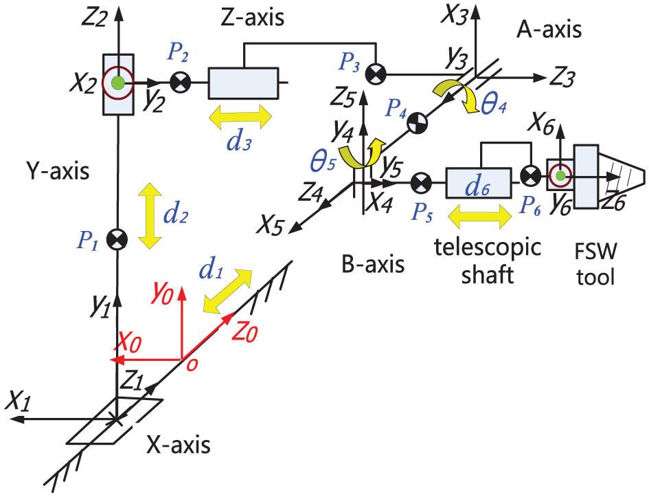
The schematic diagram of mechanism of the FSWR is shown in Figure 3.
Schematic diagram of mechanism of FSW robot.
The circle represents the positive direction of the coordinate axis perpendicular to the paper surface, the dot dash line arrow is the coordinate system of the FSW tool, the dotted line arrow is the base coordinate system, and the solid line arrow is the coordinate system of other motion axes. At the same time, in order to ensure the end FSW tool meets the
According to the above-mentioned mechanism diagram, the corresponding link parameters and joint variables are obtained, and the kinematics equation of the FSWR is established according to the principle from left to right. The link transformation


Multiplying each link transformation matrix
The general formula of the link transformation matrix

By substituting the link parameters of each joint and the initial joint variable values into the matrix

The reverse kinematics
The inverse solution of the kinematics of the FSWR is the position
From the kinematic equation (5) of the FSWR, it can be seen that the attitude matrix is decoupled, and the rotational joint variables
Using the inverse transformation method, 18 the position and posture of the end of the FSW tool are shown in equation (6)

Then, the pose matrix of the end of the FSW tool indicated by the homogeneous coordinate form is as shown in the following formula

Comparing the kinematic equation (5) of the FSWR with formula (7), we can obtain
Therefore, the angle value of the AB axis can be obtained as known from the attitude transformation matrix
According to the different welding process and the thickness of the welded parts, the unique value of Q can be determined, so that the robot’s position can be inversely solved as follows

The Pieper criterion method 19 is specifically designed to solve the situation where the three adjacent joint axes of the wrist intersect at one point.
As shown in Figure 4, the wrist joint of the FSWR is located on the B axis, and the A axis and the telescopic shaft both intersect the B axis at one point. The position of this point in the base coordinate system is


The mechanism brief of wrist.
Then solve the

The inverse of the wrist posture can be given by the following formula

Assume that the attitude of the FSW tool is as follows

The formula (8) can be obtained, and the joint variable can be obtained by substituting into the formula (11).
The Jacobian matrix and solution for velocity and acceleration of link
The Jacobian matrix is used to describe the linear mapping relationship between the operating space velocity and the joint space velocity at the end of the FSW robot FSW tool. It can be regarded as the transmission ratio from the joint space to the operating space. The Jacobian matrix has a vector product method and a differential transform method.
The vector product method is used to calculate the Jacobian matrix. Since the first 3 are moving joints and the last 3 joints are rotating joints, the Jacobian matrix has the following form
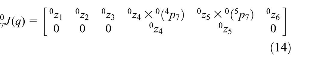
Here,
It can be derived from the kinematic equation


The final Jacobian matrix obtained is as follows

The motion of each link of the FSWR is usually expressed by the velocity and acceleration of the origin of the link coordinate system, and the angular velocity and angular acceleration of the link coordinate system. By performing coordinate transformation and theoretical derivation on the coordinate system of the connecting rod, the following equations are obtained.
1. Recursive formula for rotating joint link speed

2. Recursive formula for the acceleration of the rotating joint link

3. Recursive formula for moving joint link speed

4. Recursive formula for the acceleration of the moving joint link

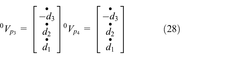
5. The formula for the recursion of velocity and acceleration at any point on the connecting rod

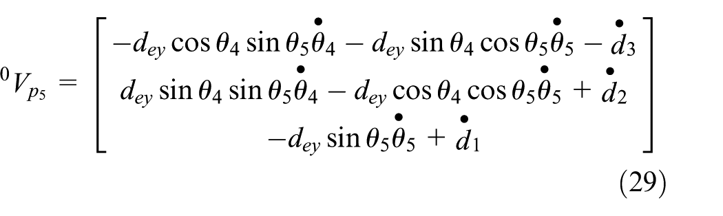
According to equations (19)–(23), the speed and acceleration of each link of the FSWR are obtained, and the speed and acceleration of each of the above-mentioned recursive links are expressed relative to the coordinate system of the link itself. Now that the velocity and acceleration are expressed relative to the overall Cartesian coordinate system D, you need to multiply the left by one rotation transformation matrix D, that is

Therefore, the

Thus, the expression of
Kinematics simulation of FSWR under typical working conditions
The welding tasks of FSWR can be mainly summarized as the following five typical working conditions: cylindrical ring seam welding, cylindrical longitudinal seam welding, melon top-ring seam welding, melon bottom-ring seam welding, and melon petal welding. Among them, melon valve welding is a complicated welding trajectory and the most severe load condition. Therefore, the kinematics simulation analysis of the FSWR is carried out by taking the melon valve welding condition as an example. The starting welding position of FSWR is shown in Figure 5. The initial position of FSWR is determined by the welding conditions of the melon petal welding and the size of the workpiece.

The initial position of robot welding.
Under the condition of melon petal welding, the welding path of the end stirring needle is a half elliptical arc. The radius of the cross-section circle at the end position of the weld is 1670 mm. In fact, the petal welding is part of the elliptical ball, but the half-axis lengths of the X, Y, and Z axes of the elliptical ball are 1670, 1050, and 1670 mm, respectively.
The weld trajectory model of the workpiece to be welded is drawn in the robot coordinate system, as shown in Figure 6. The melon valve weld is assembled from two thin-walled Al2024 aluminum alloy curved surfaces with a thickness of 5.5 mm. The weld trajectory equation formed by the two curved surfaces is shown in formula (26)


Welding seam trajectory model of melon valve welding.
In order to obtain the movement law of each joint under the condition of the melon valve welding, the coordinate measurement of the weld position is performed by installing the contact probe at the end of the FSW tool. The contact probe uses HEIDENHAIN high-precision triggering TP230 probe, which immediately outputs a high-level TTL (transistor–transistor logic) signal when it touches the surface of the workpiece. The robot controller reads the coordinates of each joint immediately after receiving the trigger signal and stores it in the register. With the PC as the host computer, the robot trajectory planning and simulation system is established on the VC platform, and the positions of the axes in the register are read through the Ethernet and robot controller protocols. In the upper computer trajectory planning system, the robot kinematics method is used and the spherical space coordinates of the end of the probe are calculated from the positions of the axes. The measurement diagram is shown in Figure 7.
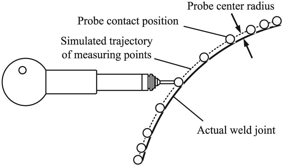
Weld measurement schematic.
Through discrete contact measurement methods, a series of discrete points with the offset of the probe radius from the actual weld are obtained. These discrete points are fitted to a spatial curve using cubic spline interpolation. There are two relationships between the measurement point and the spatial curve:
The more the measurement points, the higher the accuracy of the fitted curve;
The density of the measuring points should be increased at both ends of the weld to ensure the vector accuracy at both ends of the spline fitting curve.
During the whole welding process, the X-axis motor does not move, and its rotation speed is 0; the Y-axis and the Z-axis are associated with each other, the Y-axis is raised, and the Z-axis is extended. The angular velocity curve on the Y-Z axis motor side is shown in Figure 8(a) and (b). The A-axis should point to the radial direction of the welded ellipsoidal workpiece as the welding path changes. The angular velocity curve of the A-axis motor is shown in Figure 8(c). The B axis remains unchanged during the welding process, and the servo motor speed is 0 r/min. The insertion shaft also maintains an output speed of 0 r/min during the welding process. The FSW tool rotates at 1000 r/min and the rate of movement along the weld is 20 mm/s to ensure the quality of the welding. The attitude angle curve of the FSW tool relative to the base coordinate system of the robot base is shown in Figure 9.

The speed curve of axis in the side of motors: (a) Y-axis motor angular velocity, (b) Z-axis motor angular velocity, and (c) A-axis motor angular velocity.

The azimuth of FSW tool.
Dynamics modeling and simulation of FSWR
Center-of-mass coordinate and solution for velocity of link
The dynamic mechanism of the FSWR is shown in Figure 10.
The dynamic calculation brief of FSWR.
In the


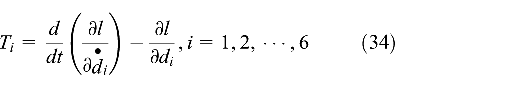
Lagrangian function and equation of motion of FSWR
1. Solving the kinetic energy of the system

Among them, IA and IB are the rotational inertia of the A-axis and the B-axis, respectively.
2. In the

3. The Lagrangian function L of the robot is solved

There are a total of 6 joint variables of
Dynamics simulation of FSWR under typical working conditions
The FSWR has the characteristics of heavy load, high rigidity, and strong disturbance. During the actual welding operation of the robot, the end load is various, and the driving torque required by different working conditions is also different. 20 The dynamics relies on the 3D solid model. The simulation method will be of great significance for the design and structural optimization of the robot body.21,22
The FSWR simulation calculation model mainly consists of the following parts, as shown in Figure 11: X-axis assembly, Y-axis assembly, Z-axis assembly (including saddle and ram), and AB shaft and agitator assembly.
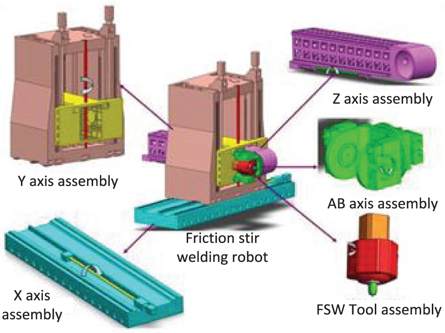
The composition of calculation model for friction stir welding robot.
Here, the first three joints of the X-Y-Z axis are the ball screw and the linear guide, and the AB axis is the rotating joint. The FSW tool includes an insertion shaft composed of a spiral pair and a stirring shaft composed of a rotary joint. Wherein, the lead of the X-axis spiral pair is 12 mm; the Y-axis and Z-axis spiral sub-lead is 20 mm; and the lead of the welded insertion shaft spiral pair is 1 mm. In order to be able to perform simulation analysis, it is necessary to simplify and merge the model. The principle of model simplification is to destroy the original structure of the model as little as possible, and to use some equivalent and approximate methods to simulate the real processing conditions of the robot.
The model input conditions mainly include the following: the unit system adopted by the model, the simplification of the model, the configuration of the initial simulation time, the material of each component, the quality of the robot, and the inertia information. The FSWR establishes a 3D model according to the proposed scheme for dynamic simulation analysis. Using ADAMS software for simulation analysis, the corresponding material properties are assigned to each part of the robot, as shown in Table 2.
The physical properties of material.

Load input conditions refer to the forces and moments that the robot is subjected to during the welding process under each typical working condition, including their size and direction. During the welding process of the FSWR, the external load input is shown in Figure 12.

The mechanics output condition of melon petal welding.
Among them, gravity is 9.8 m/s2; gravity compensation 1 is 30,000 N; gravity compensation 2 is 30,000 N; positive pressure 1 caused by gravity compensation 1 is 60,000 N; positive pressure 2 caused by gravity compensation 2 is 60,000 N; insertion resistance is 38,000 N; feed resistance is 12,000 N; and stirring torque is 270 Nm.
During the simulation of the FSWR, the unevenness of the material of the workpiece to be welded and the plasticization and friction of the material in the stirring zone 23 will cause the stirring needle to be subjected to a random wave power, as shown in Figure 13. Among them, the peak value of the wave power is 3670 N, which alternately acts on the end of the stirring needle in the direction of 0–100 s and is perpendicular to the plane of the weld.

The curve of wave power.
The action flow of the entire melon petal welding process is shown in Figure 14(a)–(d).

The welding process of melon petal welding: (a) step 0, (b) step 200, (c) step 500, and (d) step 1000.
Due to the large number of curves available for simulation analysis, only some of the relevant simulation analysis curves are listed here, as shown in Figures 15 and 16.

The load of screw shafts on the working condition of seam welding conditions: (a) X-axis screw axial force and (b) Y-axis screw axial force.

The output load of axis motors on the working condition of melon petal welding: (a)Y-axis motor output torque and (b) A-axis motor output torque.
The simulation result of the above joint motor torque is the driving torque required for the macro rotation of the joint. If the driving torque of the corresponding motor is to be calculated, it needs to be converted to the actual driving torque of the motor according to the size of the transmission ratio. 24 The output torque of the motor can be used as a reference for its selection. The maximum torque of each joint motor under the above five typical working conditions is extracted and sorted out as shown in Table 3.
The torque of joints on the side of motors.

The force and torque on the joint of FSWR are the force and torque acting on the functional components of the robot feed system. These data can be used as a reference for the selection of these components. The force and torque of each joint are shown in Table 4.
The resultant force and torque of each joint.
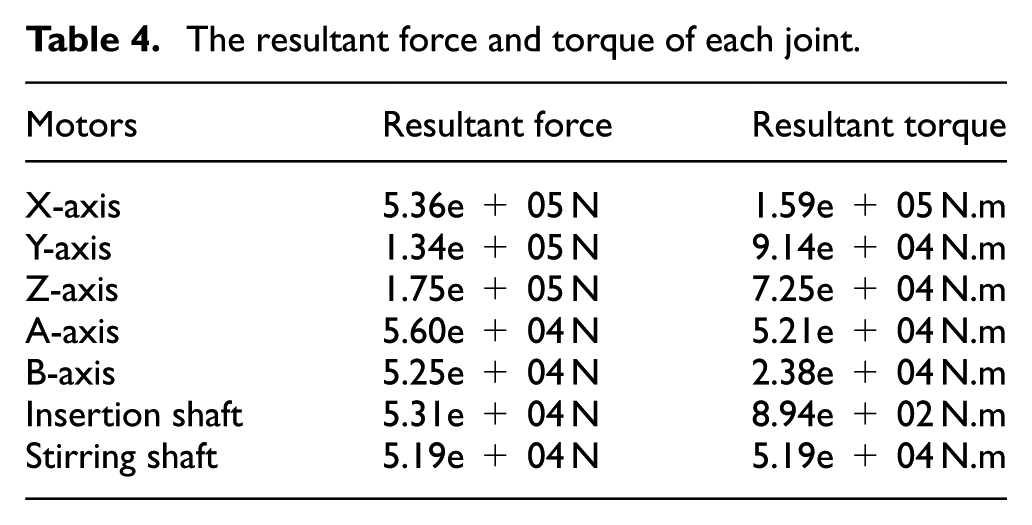
Through the simulation analysis of dynamics, the force and torque values of each motor and joint can be calculated more intuitively and conveniently. The analysis finds that these are within the design considerations, thus ensuring the selected motor and functional components. All are within the scope of safety.
Conclusion
The kinematics equation of the FSWR is obtained through the forward and inverse solutions of kinematics and the derivation of Jacobian matrix, thus the kinematics model of the FSWR is established. The dynamic model of FSWR is established by Lagrange method.
The trajectory equation of the workpiece weld under the condition of melon valve welding is established, and the spline fitting of weld trajectory is carried out by contact probe, thus the trajectory planning of each joint of FSWR is obtained.
According to the kinematics and dynamics equations of the robot, the simulation analysis based on virtual prototype technology is carried out. The results show that in the simulation process of the FSWR, the plasticity and friction of materials in the weld zone will lead to random wave force on the end-effector of the robot, and the welding process will act on the end of the robot alternately.
The variation rules of parameters in the design process of the robot are obtained by simulation, and the motion rules and load conditions of each joint of the robot are finally mastered. It provides theoretical support for the analysis of static and dynamic characteristics and structural optimization of the whole robot.
Footnotes
Handling Editor: James Baldwin
Declaration of conflicting interests
The author(s) declared no potential conflicts of interest with respect to the research, authorship, and/or publication of this article.
Funding
The author(s) disclosed receipt of the following financial support for the research, authorship, and/or publication of this article: This research is supported by the National Natural Science Foundation of China (Grant No. 51505470), Youth Innovation Promotion Association, Chinese Academy of Sciences (CAS), and “Jiang Xingsong Innovation Fund”, Shenyang Institute of Automation (SIA).