
Abstract
When controlling friction stir welding, effort must be given to maintaining proper tool shoulder contact with the workpiece in order to achieve consolidation of the parent materials. Axial force control has been used prior with some success. The research presented in this article examines the controlling of welding torque as an alternative to force control. A mathematical model of welding torque was enhanced for the design and study of convex shoulder profiles. Focus was placed on linearizing the response between plunge depth and torque. The model predicted that a spherical profiled shoulder was preferred for a more linear response. In conjunction with the spherical shoulder, a closed-loop torque controller was implemented and its performance evaluated. Welding torque for feedback control was sensed indirectly through the spindle motor current using a commercially available clamp-on current meter. The system produced 1/4 in (6 mm) bead-on-plate welds that were 10 ft (3 m) in length. Over the course of the welds, the torque controller responded to workpiece elevation changes of 1/8 in (3 mm) and 1/4 in (6 mm). Results show that the tool maintained a near constant plunge depth into the workpiece as the tool traversed along the workpiece. It was concluded that the presented method of torque control is a reliable and less complex alternative to axial force control of friction stir welding.
Introduction
As an evolving technology in the field of material joining, friction stir welding (FSW) has emerged as an active process for fabricating vehicles in the aerospace, automotive, and maritime industries. FSW is a solid-state welding process that is advantageous for joining metals with low melting points such as aluminum. It was discovered by Wayne Thomas of the Welding Institute and patented in 1995. 1 Unlike the more commonly used fusion welding process such as arc and resistance welding where melting of the parent metals occurs, the workpiece in FSW remains in the solid state due to a lower process temperature. Because the welding process is solid state, finer grain microstructure is produced, which results in greater mechanical strength. 2 In addition, no filler material is required and no welding fumes are produced which is advantageous for cost, safety, and environmental reasons. In contrast, when trying to weld aluminum via shielded metal arc welding, which is commonly referred to as stick welding, porosity and lower mechanical strength often result.
Conventional FSW utilizes a rotating tool to join the parent metals, as illustrated in Figure 1. The rotating tool consists of a shoulder and a probe (also referred to as a pin) usually fabricated from steel. The probe is typically harder than the workpiece material. According to Schneider, 3 as the rotating tool traverses along the faying surface, the probe plastically deforms the parent materials by continually rotating the material around to the backside of the pin. Once at the backside, pressure that is underneath the shoulder forges the parent materials together. Heat generated from friction, as well as the heat released in the plastic deformation process, softens the parent materials and aids in the stirring of the deformed material.
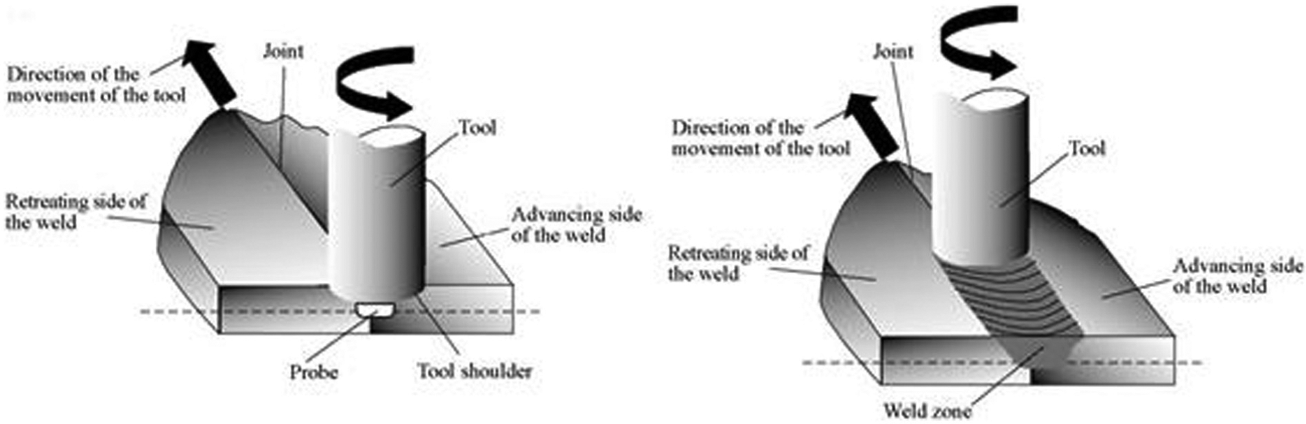
The FSW process. 4
A critical requirement of the process is the proper engagement of the tool with the workpiece. Without the proper engagement of the tool with the workpiece, forging pressures required for consolidation are not achieved. This results in welding flaws such as wormholes which reduce the structural integrity of the weld. Maintaining proper engagement of the tool with the workpiece (or plunge depth) is challenging because of workpiece variation and machine deflection. Workpiece variations present challenges with large and curved components such as the fuselage of a rocket or an aircraft. As the FSW tool traverses along the weld seam, unexpected variations or changes in the curved surface require adjustments to the tool’s position during the process. For instance, if the tool is too deep into the workpiece, excessive weld flash emerges and results in reduced weld strength. When the tool is not deep enough, inadequate forging pressure emerges below the tool and results in wormholes, which, in turn, reduce the weld’s strength.
For controlling FSW, current state-of-the-art systems can use force control to maintain the proper plunge depth of the tool into the workpiece. A force gauge is placed in line with the FSW tool to measure the downward force exerted by the tool. The measured force is compared to a desired force that is known to produce good welds. Any difference between the desired and measured forces is converted into a control signal and used to change the tool’s plunged depth during the welding process. As an example of its importance, Talwar et al. 5 of Boeing have noted that “Successful friction stir welding (especially for lap joints) requires welding under force control.”
Force control is a vital control method for the automation of FSW, in particular when the welds are performed robotically. Similar to other welding technologies, the application of FSW with robots provides a very flexible platform for automation, which can result in increased productivity and profits for businesses. However, with FSW the relatively large forces present a challenge. The load-bearing capability of robots is limited. In addition, their compliant nature makes FSW much more challenging. To address the compliance problem, force control has been presented as a solution. With robotic FSW, the challenge is to keep the tool positioned correctly with adequate force on the tool, while the linkages of the robot continually reposition themselves. The motion of the linkages, along with their reaction to the large welding forces, results in positioning errors of the tool. In conjunction with these positioning errors, large fluctuations in the forging force occur within the welding environment. These positioning errors and force fluctuations will possibly lead to insufficient deformation, forging, and consolidation of the parent materials. With force control, constant axial force is maintained on the tool and the likelihood of welding flaws is diminished.
Prior research has successfully demonstrated FSW using force control. Longhurst et al., 6 Smith, 7 Soron and Kalaykov, 8 and Zhao et al. 9 each used different approaches and concluded that it is feasible to develop and implement force control architectures for FSW. However, each also concluded that limitations do exist. Longhurst et al. identified the key enablers associated with the interaction between the tool and the workpiece. Their force controller was a simple proportional-, integral-, and derivative-based system that resided outside an existing position controller on a FSW machine. They concluded that a portion of the shoulder of the FSW tool must remain above the workpiece surface at all times for stability to be maintained. In addition, a smooth motion profile and large lead angles for the tool contribute to stability. Smith set up a force control architecture on an articulating arm robot by exploiting a Jacobian relationship 10 between the motor torques and the axial welding force. He was successful using this novel approach for a limited range of process speeds. Similarly, Soron and Kalaykov experienced stability issues when force oscillations occurred as the tool first made contact with the workpiece. Zhao et al. modeled the dynamic behavior of the interaction between the FSW tool and workpiece and then created a nonlinear controller based upon the model and experimentally obtained parameters.
From the prior research described above, it can be concluded that although in use today, force control of FSW does have limitations and drawbacks. For instance, the process is highly nonlinear and thus applicable to a limited range of process parameters. Issues can arise when long welds of several feet or meters are made. Over the course of long welds, varying thermal conditions can emerge and cause instability in the control system. In addition, a force gauge is needed, which increases the cost and complexity of the FSW system.
Presented research
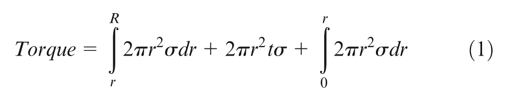
The research presented in this article introduces the innovation of torque control of FSW. The research was funded by the National Aeronautics and Space Administration. Controlling the welding torque is proposed as an alternative to force control of FSW in order to create a reliable welding system that is robust, simpler, and less expensive. The presented innovation of a simplified and novel method of torque control of FSW was introduced by Longhurst et al. 11 Prior and more elaborated methods of torque control of FSW are documented in patents by Burford et al. 12 and Yoshinaga. 13 Burford et al. developed a method for controlling torque via adjusting tool rotation, traverse speed, as well as plunge depth. Their invention is intended for FSW machines that have multiple actuators capable of controlling these process parameters. Similarly, Yoshinaga developed a method for controlling motor torque on large multiple axis coordinate machines by monitoring and adjusting the tool position. The new concept presented herein is based upon the mathematical relationship defining welding torque as the product of the shear flow stress in the parent materials and the distance to the shear interface boundary where plastic deformation and forging occurs during the welding process. This relationship was identified by Nunes et al. 14 The resulting equation that defines the total welding torque is the summation of the torque acting at the shear interface boundary that surrounds the tool (see equation (1)). The value of the torque is significant because it indicates how far the tool is plunged into the workpiece. Proper engagement (plunge depth) of the tool into the workpiece is critical for producing good welds.
The goal of this research project was to develop and demonstrate the feasibility and advantages of torque control by producing welds of up to 10 ft (3 m) in length. Within this goal were two technical objectives. The first technical objective was to automatically maintain proper tool engagement with the workpiece while encountering workpiece variation in geometry and misalignment, machine (robot) or workpiece deflection, and changing thermal conditions in the welding environment. The second technical objective was to provide a FSW control system that reduces the amount of capital investment required for process automation by eliminating force gauges and utilizing the spindle motor current as the control feedback signal.
To accomplish our goal and meet the technical objectives, our work plan had four elements. Prior to welding, a prototype FSW tool was developed to produce a linear relationship between the welding torque and the tool’s plunge depth into the workpiece. The prototype design was guided by equation (1). Second, a method was developed to measure the welding torque from outside the welding environment. Research was focused on using a commercially available clamp-on current meter to read the electrical current supplied to the spindle motor. The motor’s current is a function of torque and provided an indirect measurement of the welding torque. Third, a closed-loop control architecture was designed and implemented to control the welding torque. The feedback signal of torque was obtained from the spindle motor current. Fourth, the welding process was demonstrated.
Modeling
During the welding process, it is required that the shoulder of the tool remains in contact with the workpiece in order to forge together the plastically deformed material that comprises the workpiece. The purpose of torque control is to maintain a desired welding torque which results in a weld of excellent quality. Thus, understanding the relationship between torque and shoulder contact with the workpiece is key to developing a reliable control system. As a change in shoulder plunge depth occurs, an identifiable change in torque is needed.
Previous work by Nunes et al. 14 produced equation (1) shown above. It predicts the welding torque to be the summation of the product of shear flow stress occurring at the shear interface boundary that surrounds the tool and the distance to the axis of rotation. This equation is valid for tools with a flat shoulder. Upon further inspection of equation (1), one will notice that a rather large increase in torque will instantaneously occur when the shoulder contacts the workpiece, assuming no lead angle. Thus, maintaining the proper welding torque while not plunging too deep and generating weld flash is a very challenging task. A highly responsive control system would be required to accomplish this task. Most conventional FSW operations place the tool on a small lead angle which allows gradual contact of the shoulder. However, the relationship between torque and plunge depth is not linear when the tool is on an angle.
For torque control, a linear relationship between plunge depth and torque would be ideal. As the plunge depth increased, so would the torque by a proportional amount. The opposite would be true when the plunge depth is decreased. By monitoring and controlling the torque, the tool would maintain a certain plunge depth associated with the value of torque.
The following analysis examines the relationship between torque and shoulder plunge depth for tools with convex shoulders. A convex profile provides a change in the amount of shoulder contact as the plunge depth changes, while eliminating the need for the tool to be placed on a lead angle. The analysis assumes steady-state conditions related to welding temperature and shear flow stress. These assumptions can be supported when joining aluminum 6061 and other materials with similar relationships between yield stress and temperature. When aluminum 6061 is heated to welding temperatures in the range of 600–1000°F, the strength is nearly constant. 15 Thus, the temperature in the welding environment that surrounds the tool can vary greatly, but the resulting shear strength and torque will remain nearly constant.
For the analysis of a convex tool shoulder, the following variables are defined. The constant σ (lb/in2) (N/m2) is the shear flow stress at the shear interface boundary surrounding the shoulder. The variable r is the radial coordinate of the shoulder (in) (mm). The variable z is the vertical coordinate of the shoulder (in) (mm). The variable S is the surface area of the shoulder (in2) (mm2). The variable PD is the plunge depth of the tool (in) (mm). An illustration of these variables is provided in Figure 2. Note that the illustration of the convex shoulder shown in Figure 2 is not to scale, and its profile and surface area are exaggerated for the purpose of defining the variables.
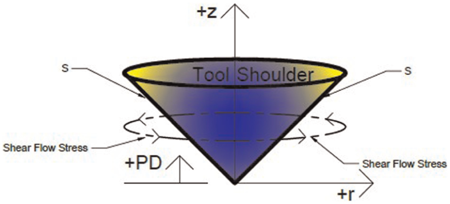
Illustration of a convex tool shoulder and variables for analysis.
Using Calculus, 16 the area of a surface of revolution is given by equation (2)
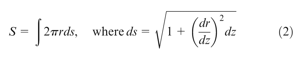
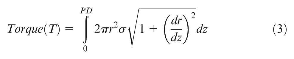
For determining welding torque, add (r·σ) to the area of surface of a revolution equation (equation (2)), which results in equation (3)
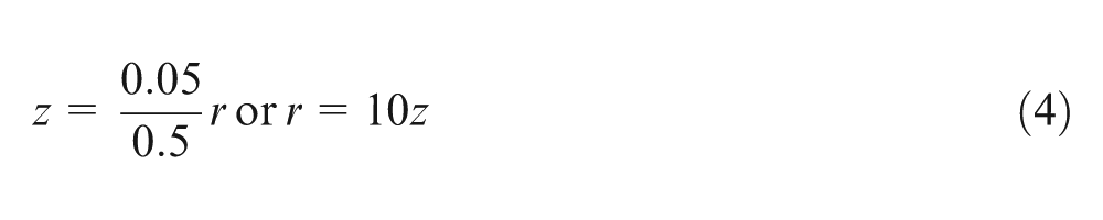
For a linear tapered shoulder with a height of 0.05 in (1.27 mm) and a radius of 0.5 in (12.7 mm), equation (4) is an equation of the line that represents the profile of the shoulder
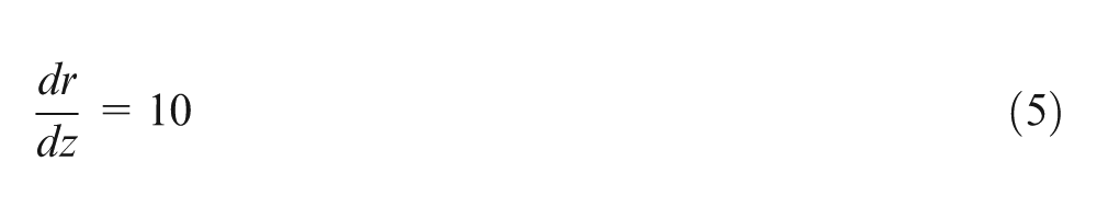
Differentiating with respect to z produces equation (5)
Substituting equations (4) and (5) into equation (3) yields
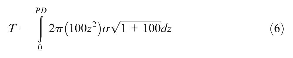
Simplifying equation (6) yields
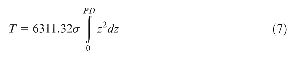
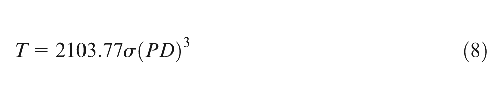
Performing integration of equation (7) produces equation (8) which defines torque (T) as a function of plunge depth (PD)
For a domed spherical shoulder with a height of 0.05 in (1.27 mm), a radius of 0.5 in (12.7 mm), and an arc radius of 3.0 in (76.2 mm), equation (9) is an equation of the line that represents the profile of the shoulder
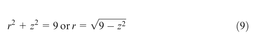
Differentiating equation (9) with respect to z produces equation (10)
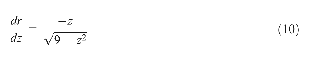
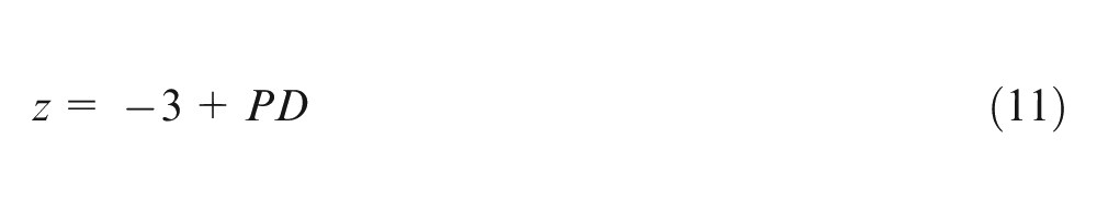
For the analysis of the spherical shoulder, the origin of the coordinate system is 3 in (76.2 mm) above the shoulder. Thus, the relationship between plunge depth (PD) and z is given by equation (11)
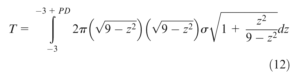
Substituting equations (9)–(11) into equation (3) yields
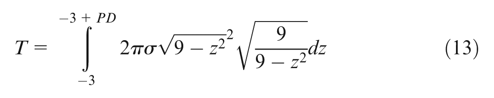
Simplifying it yields
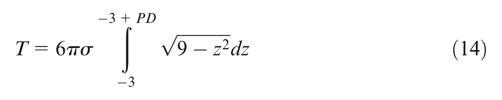
Further simplification yields equation (14)
Utilizing trigonometric substitution, we can rearrange the portion to be integrated in equation (14). Changing the limits of integration in equation (14) yields
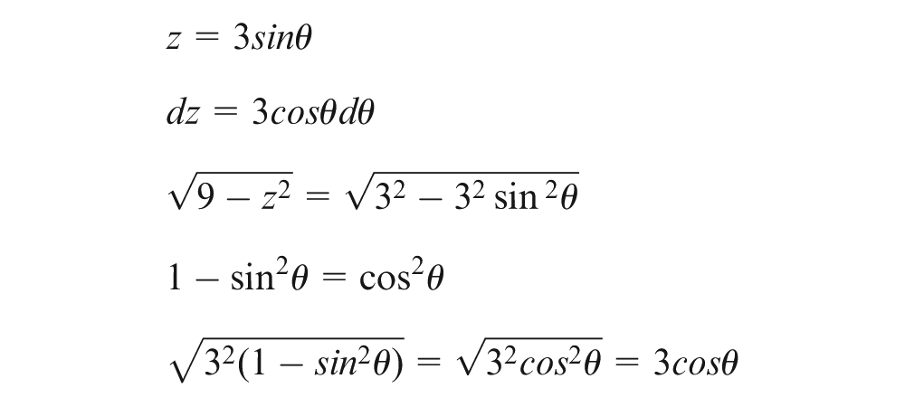
From equation (11), when PD = 0, z = −3, therefore
Rewriting equation (14) using the above identities yields equation (15)
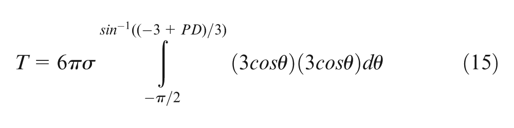
Simplifying equation (15), the following can be obtained
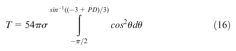
Using the trigonometric identity, we can further simplify equation (16)
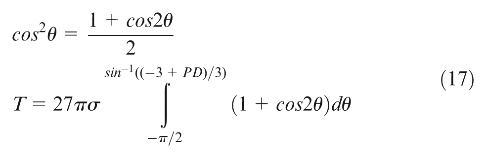
Performing integration of equation (17) yields equation (18), which defines torque as a function of plunge depth
From these calculations, we have equation (8), which defines torque on a tapered shoulder as a function of plunge depth, and we have equation (18), which defines torque on a spherical shoulder as a function of plunge depth. These two equations are plotted in Figure 3.
Predicted shoulder torque.
Upon inspection of Figure 3, one can notice that although both the spherical and tapered profiles predict a change in torque as the plunge depth changes, the spherical shoulder has a more linear relationship. To validate our modeling and the predicted relationship between torque and plunge depth, several welds were made using both the tapered and spherical shouldered tools. The process parameters used for the validation were 1400 r/min for the tool rotation speed and 9 in/min (228 mm/min) for the traverse speed. Both tools successfully produced welds free of defects, and the torque increased with plunge depth. Due to noise in the dynamometer and resolution limits, we were not able to distinguish a more linear response with the spherical tool as compared to the tapered tool. However, because the model predicted a more linear response, we chose to use the spherical tool for the torque control operations described below. Figure 4 shows the fabricated spherical shouldered tool.
Prototype FSW tool for use with torque control (spherical shoulder).
Experimental setup
The welding research was conducted using the FSW system at Vanderbilt University. The FSW system was a Milwaukee model K milling machine that had been retrofitted with servo motors and force-measuring instrumentation. The system’s controls were open architecture.
For this research, a torque control algorithm was implemented to maintain a constant plunge depth of the FSW tool into the workpiece. The algorithm consists of an outer torque control loop that enclosed the position-control loop associated with the plunge depth. The control algorithm is illustrated in the diagram of Figure 5. The controller was tuned using the Ziegler–Nichols method. 17
Designed and implemented FSW torque control system.
What was unique about the control system was the indirect measurement of welding torque via the spindle motor current and a commercially available clamp-on current meter (see Figure 6). Initially, the plunge depth was set via the position controller at the beginning of the welding operation. After the tool traversed a short distance, the torque controller was engaged. The actual value of torque was not important for this operation. Maintaining a constant torque throughout the welding process was important because it was associated with a constant plunge depth.
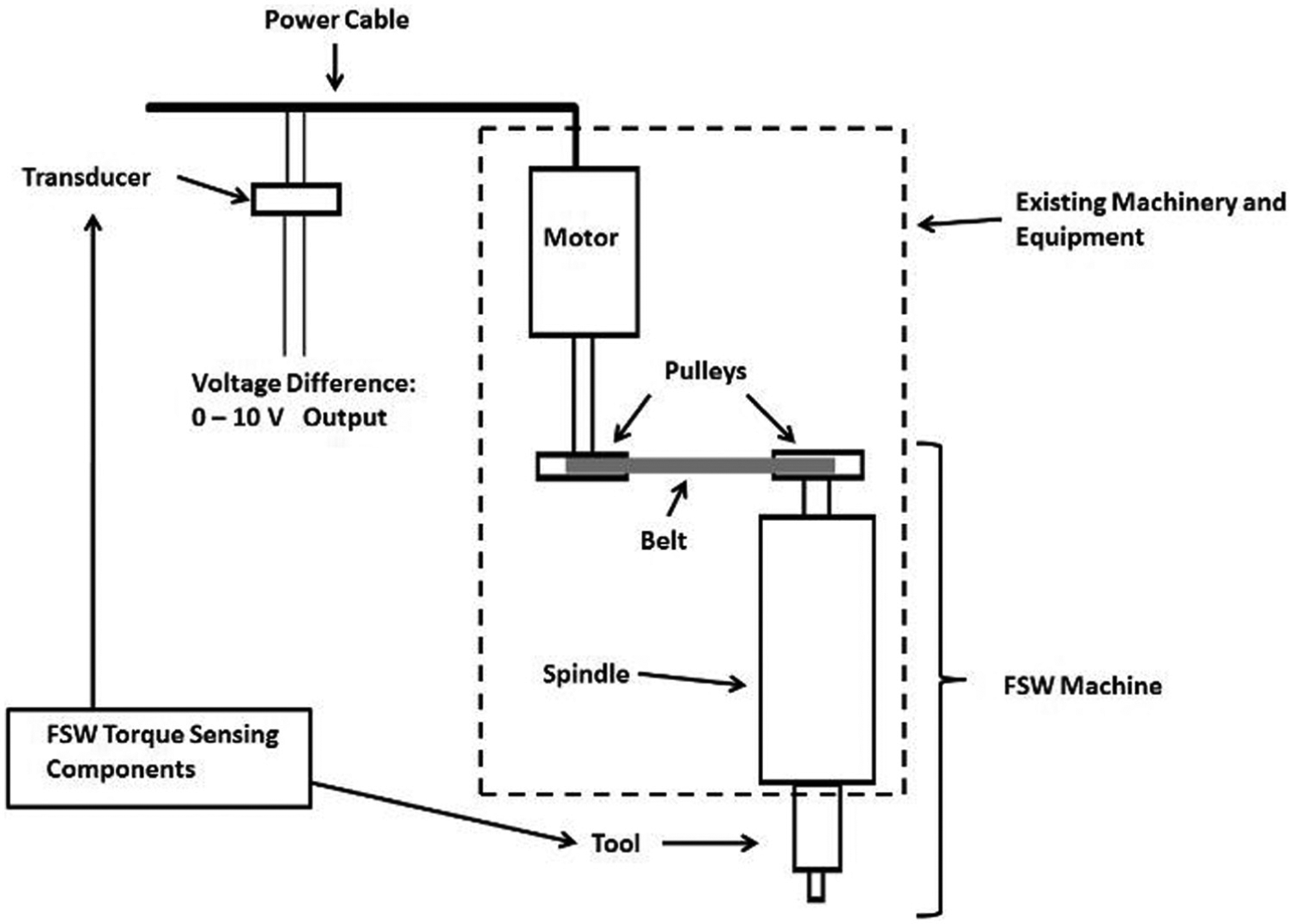
Sensing torque acting on the tool via motor current.
The selected clamp-on current meter was from NK Technologies (model number AT2-010-000-SP). The current transducer was placed inside the electrical disconnect box that feeds power to the spindle motor’s variable frequency drive (VFD). Thus, the transducer measured both the real and reactive power to the VFD and the spindle motor. The 0–10 V direct current (DC) output of the current transducer was connected to the master weld control computer via a National Instruments data acquisition board (model number: NI USB-6008). Using the data acquisition board with its 11 bit analog input, in conjunction with the current transducer, provided a resolution of 0.05 A per bit.
Prior to our torque-controlled welding operations, we were able to validate this sensing method by performing several welds and recording both the current and the torque. It was observed that the motor current trended directly with the welding torque for the range of process parameters tested. In general, it was found that the motor current was about 60% of the motor torque. In addition, as the plunge depth was changed, both the torque and motor current changed a proportional amount. The results are shown in Figures 7 and 8.
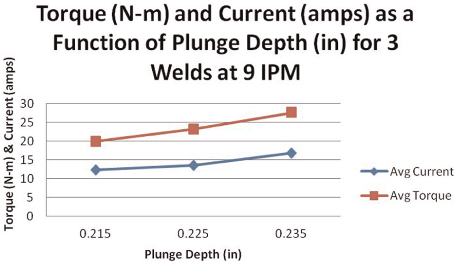
Torque and spindle current.
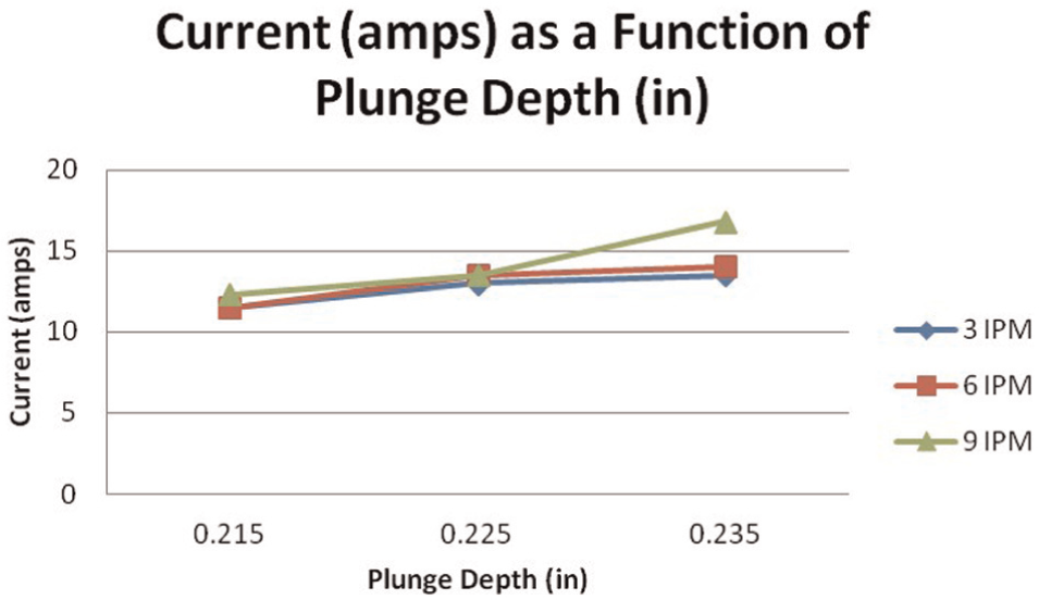
Spindle current.
For each torque-controlled welding trial, a 10 ft (3 m) long bead-on-a-plate weld was produced on a 1/4-in-thick plate of aluminum 6061-T6 using the spherical profiled tool shown in Figure 5. Once the tool was plunged into the workpiece and traversed approximately 1 in (25.4 mm), the torque controller was engaged. The value of motor current (or torque) at the instant the torque controller was engaged was automatically selected as the reference value (also known as the command value). The controller simply adjusted the vertical position of the tool relative to the workpiece to maintain a constant current, which, in turn, correlated with a constant plunge depth and welding torque.
To test the robustness of the control method, the workpiece was placed at an angle relative to the machine’s worktable. Panels were also welded in the horizontal position for comparative purposes. Two different slopes were utilized. The sloped conditions were created using 1/8 in (3 mm) and 1/4 in (6 mm) shims. The shims were placed underneath the backing plate at one end. The tool traversed approximately 20 in and then moved laterally a small distance before traversing in the opposite direction. This required the tool to traverse up and down the slope as well as to start and stop multiple times while operating in the torque control mode. Travel speeds of 9, 12, and 14 in/min were used while the tool rotated at 1400 r/min. Photographs of the welding setup and a welded paned are shown in Figures 9 and 10.
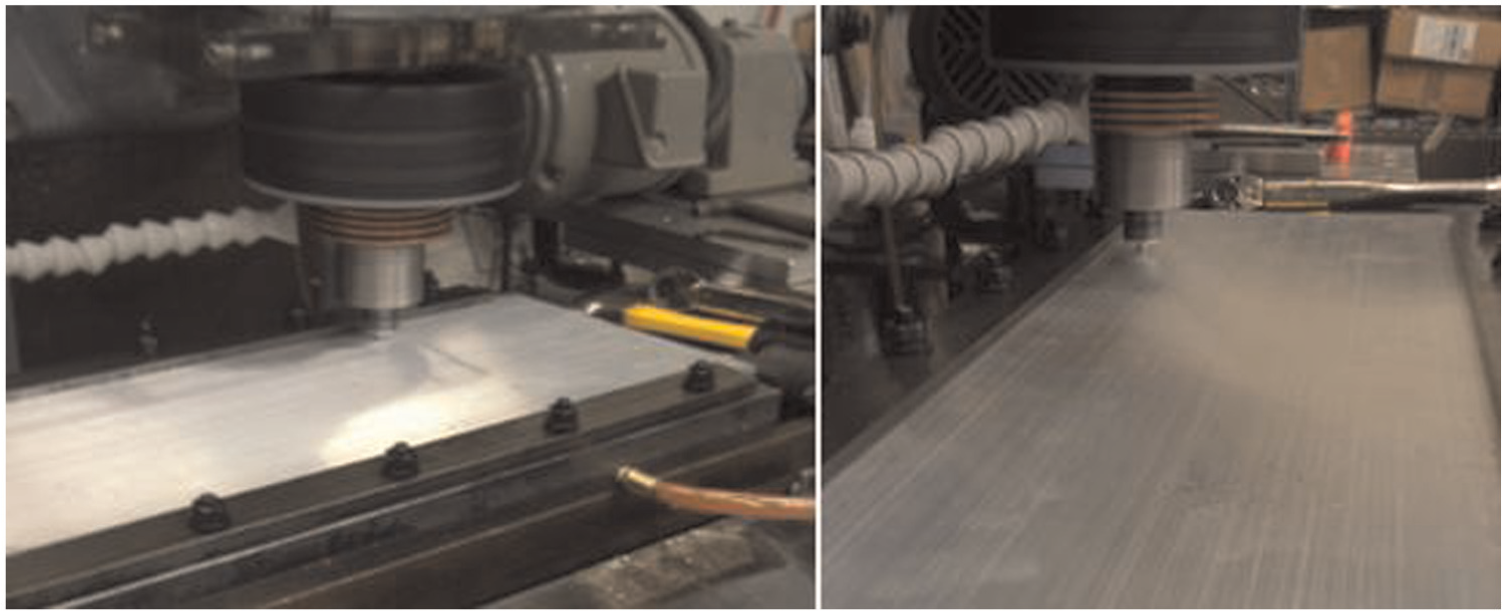
FSW tool plunging into panel to be welded.
Completed bead-on-a-plate weld.
Results and discussion
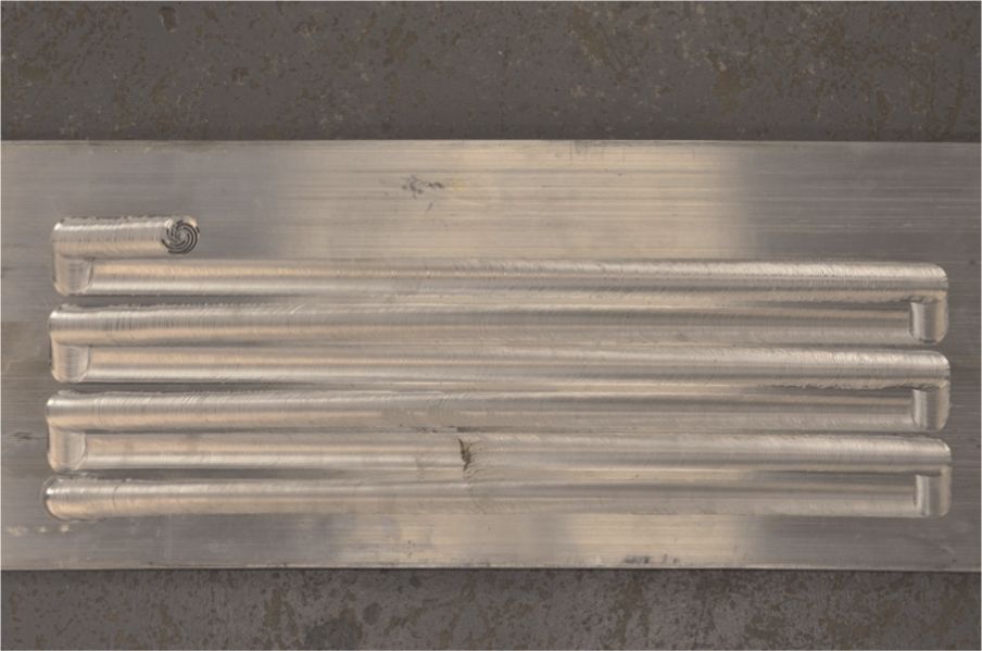
To illustrate the value of torque control and to serve as a baseline for comparison purposes, we welded a flat workpiece without the use of torque control (i.e. position control). The results can be seen in Figures 11 and 12. Notice the excessive weld flash that was generated due to the inability of the tool to adjust its vertical position as the welding environment changed over the course of the operation. Including the initial plunging of the tool, the welding operation lasted approximately 20 min. During this time, the workpiece experienced significant thermal changes which led to thermal expansion, softening, and distortion of the workpiece. The fixed plunge depth created a weld that was clearly unacceptable due to the large amount of flash and ample digging of the tool into the workpiece.
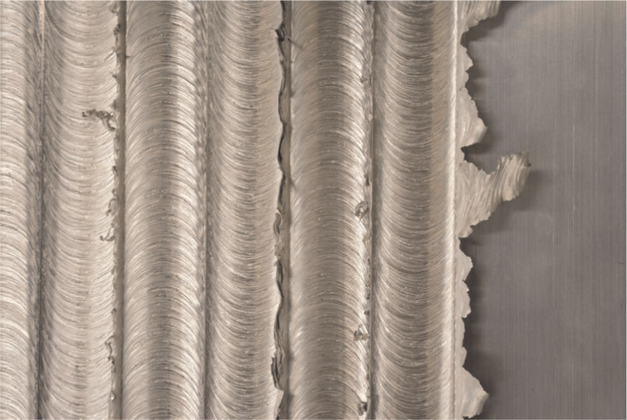
Weld without the use of torque control.
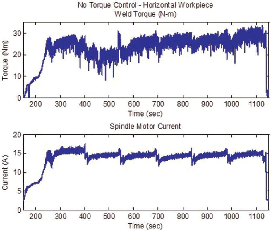
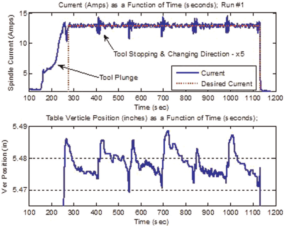
Resulting variation in current and torque due to no torque control.
Figure 12 shows how the welding torque and spindle current varied over the course of the 10 ft (3 m) long weld. The welding torque varied about 15 N m over the course of the weld. The motor signal did not contain as much noise as the torque signal and more detail can be seen within. Each time the tool’s velocity changed, such as when it stopped, changed direction, and then started again, a sudden fluctuation in the current occurred. These fluctuations align with the weld path shown in Figure 10. The fluctuations at the approximate times of 400, 550, 700, 850, and 1150 s correspond to when the tool moved lateral and then reversed its direction of travel across the plate.
The results of torque control with a flat horizontal workpiece can be seen in Figure 13. Notice how there is no flash even though the workpiece had significant thermal changes during the 20-min-long welding operation. Although not visually evident in Figure 13, once the workpiece was removed from the welding fixture after the operation was complete, the panel was significantly distorted due to the elevated temperatures experienced during the operation. Once removed from the constraints of the clamps in the welding fixture, the panel was arched by approximately 1 in (25.4 mm) over the length of the panel. Prior to welding, it was completely flat. This provided evidence of the torque controller’s ability to track the surface of the workpiece and maintain a constant plunge depth into the workpiece by using feedback of the spindle motor current. The results further strengthen the mathematical model of torque given by equation (1). The model indicates that torque is strongly dependent upon plunge depth, and we assumed that the strength of the material will vary little over an elevated and large temperature range.
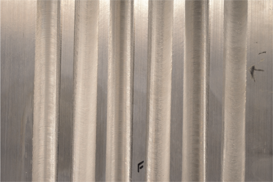
Results of torque control on a flat workpiece.
Figure 14 shows the spindle current and the vertical position of the worktable (i.e. plunge depth). To adjust the position of the tool in order to maintain a constant plunge depth into the workpiece, the machine actually adjusted the vertical position of the worktable where the workpiece was mounted. The spindle’s location, and hence tool, was fixed. If the opposite configuration was present with the tool moving vertically, the process would be equally effective. The worktable was varied throughout the torque-controlled region of the weld in order to regulate the current to the desired value. The torque controller engagement is noted by the appearance of the dotted line in Figure 14, which is labeled desired current. From Figure 14, we can see that the worktable’s position varied about 0.02 in (0.5 mm). Once again, the current signal was relatively free of noise and provided sufficient enough resolution to see when the tool’s motion changed.
Spindle current and worktable position for a flat workpiece.
The torque controller was also successful in adjusting to changes in the workpiece position. The changes included slopes where a 1/8 in (3 mm) and 1/4 in (6 mm) increase or decrease in workpiece height occurred over a span of 20 in (0.5 m). The tool was able to maintain a constant plunge depth as the height of the workpiece varied. Over the course of a 10 ft (3 m) long weld, the tool had to adjust to a total of six slopes. While three of the slopes required the tool to rise up, the other three required the tool to lower to maintain a constant plunge depth. Figures 15 –18 show the results of toque control on a workpiece with a 1/8 in (3 mm) slope. From these figures, one can see that the adjustment of the plunge depth enables the system to maintain a constant current. Additionally, no flash was observed. Note in Figure 16 that the worktable moves vertically 1/8 in (3 mm), which is the same elevation as one end of the panel is positioned. Thus, these data provide further evidence that the torque controller was functioning properly. In addition, Figure 17 indicates that the motor current trended with the actual welding torque, thereby indicating that the current can be used to indirectly sense torque for the process parameters used in this experiment. The spindle current is the controlled parameter, but it results in a nearly constant welding torque. This observation further supports the elimination of expensive load cells and dynamometers associated with force control techniques.
Results with workpiece on a 3 mm slope.
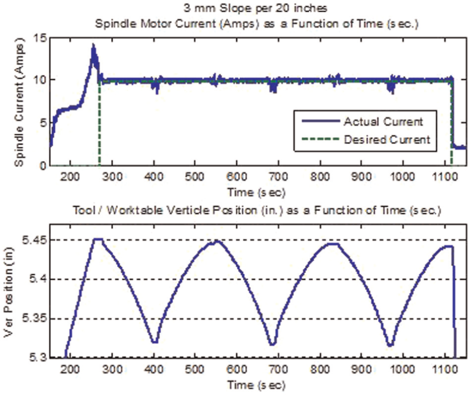
Controlled current and adjusted workpiece position for a 3 mm slope.
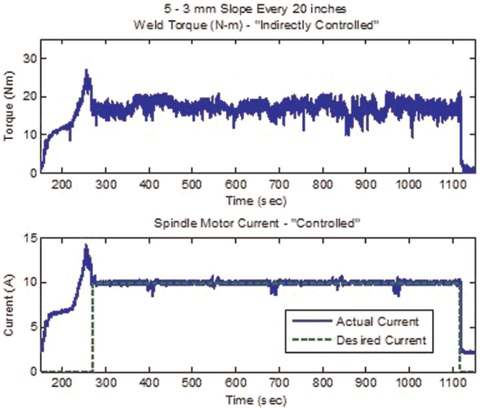
Indirectly controlled weld torque as a result of controlled spindle current.
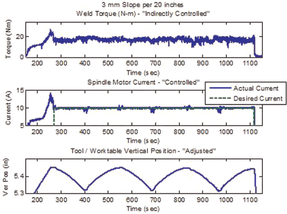
Torque, current, and worktable position for a workpiece on a 3 mm slope.
Similar results occurred with workpieces on 6 mm slopes. The results can be viewed in Figures 19–21. A little more noise appeared in the current signal as compared to the panels welded on the 1/8 in (3 mm) slopes. This might indicate that the system is approaching the upper limit for the magnitude of the slope the tool can traverse. However, the system did perform satisfactorily under the conditions imposed in the experiments detailed herein.
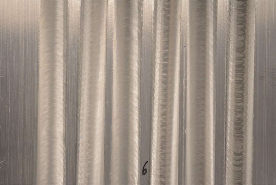
Welded workpiece while on a 6 mm slope.
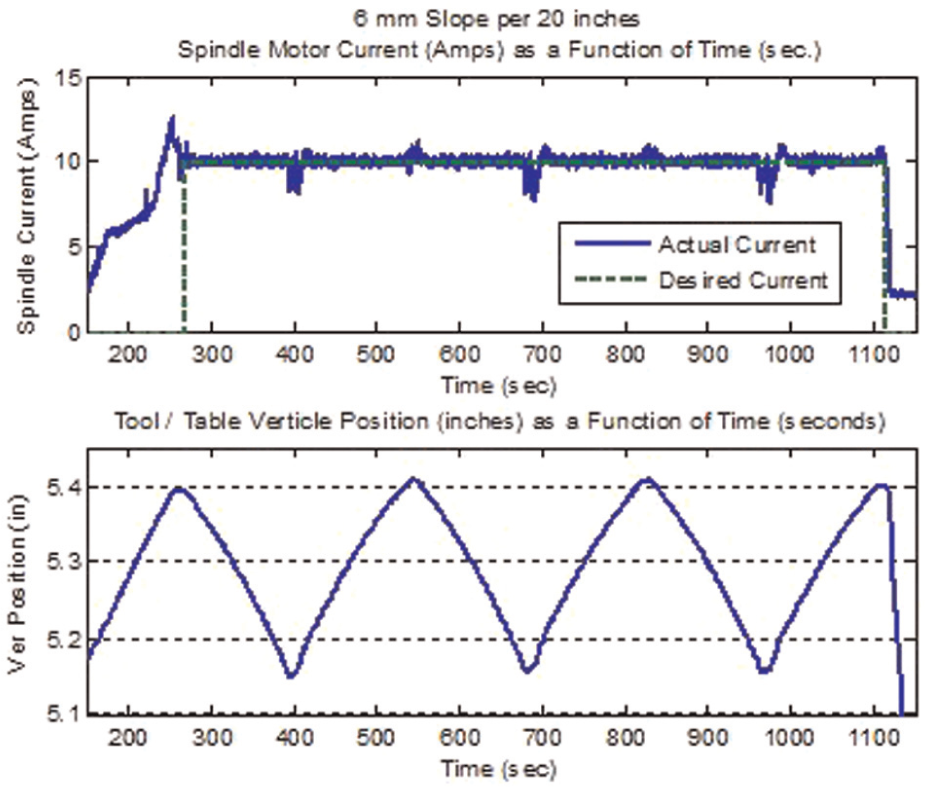
Current and worktable positions on a workpiece with a 6 mm slope.
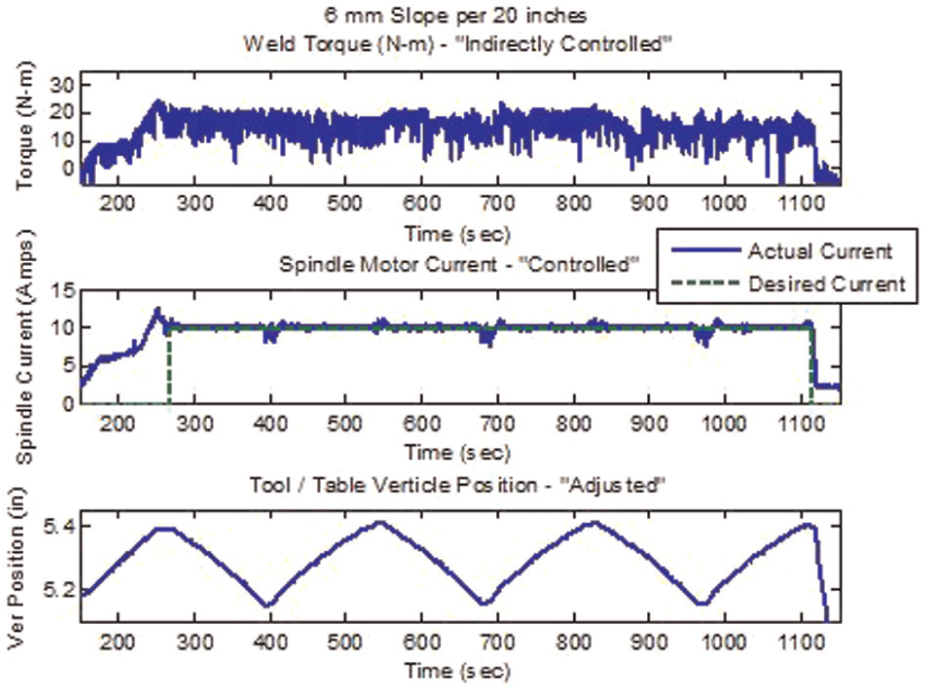
Torque, current, and worktable position for a workpiece on a 6 mm slope.
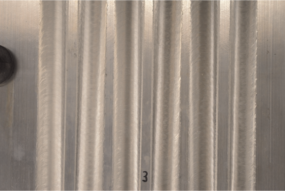
Finally, as part of our research, weld quality was verified. Several samples were examined, and all were found to be satisfactory and free of internal voids. Figure 22 shows two macro-cross sections of the 1/4 in (6.4 mm) welds produced with the spherical tool. The macro-cross sections were prepared by etching and polishing the surfaces. The results of the cross sections further validated the tool’s and the torque controller’s ability to produce quality welds.
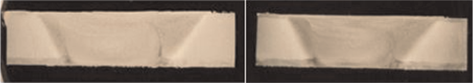
Macro-cross sections of 1/4 in welds from the spherical tool (1× magnification—not to scale).
Conclusion
With further testing and validation, torque control could become a viable replacement for force control of FSW. The mathematical model of torque predicts the strong influence of plunge depth. The results support this prediction regarding plunge depth. As the welding environment changed, whether it was due to thermal or positional changes in the workpiece, the torque was maintained by adjusting the tool’s position. We believe that applying this technique in a production setting to very long welds of 30–40 ft (9–12 m) in length would be effective.
A key enabler of the torque controller was the convex profile of the tool’s shoulder. The presented modeling showed that a spherical profile will have a slightly more linear response than a tapered shoulder and thus provide more robustness in the control system. Welding experimentation further supported the robustness as the tool in conjunction with the applied controller was able to track the changing surface of the workpiece and produce a weld free of defects.
Perhaps the most interesting and beneficial finding was the use of spindle motor current as a feedback signal to the torque controller. The gathered data showed a correlation between spindle motor current, welding torque, and tool plunge depth. Indirectly sensing the torque through the motor current enabled the torque controller to make the necessary adjustments to the tool’s position in order to maintain proper contact with the workpiece. This method resulted in quality welds. The current signal provided a relative measurement of torque and not an absolute value of torque. However, an absolute value was not needed for the torque controller to function properly. Once the proper plunge depth was set using position control and under the supervision of an operator, the torque controller simply maintained that plunge depth over the duration of the remaining operation.
By using an inexpensive current sensor, a force gauge or dynamometer is no longer needed. This allows for a reduction in capital investment for users of FSW as well as simplifies the control system. In addition, a model of torque is available to provide greater insight into the welding environment.
Footnotes
Appendix 1
Declaration of conflicting interests
The authors declare that there is no conflict of interest.
Funding
This research received no specific grant from any funding agency in the public, commercial, or not-for-profit sectors.