
Abstract
This article analyzes the forward kinematics and inverse kinematics of the seven-degree-of-freedom exoskeleton rehabilitation manipulator. Denavit–Hartenberg coordinates are used to model the forward kinematics, and the working space of the end effector of the manipulator is analyzed according to the joint motion range of the human arm. In the inverse solution of the seven-degree-of-freedom exoskeleton rehabilitation manipulator, the self-motion angle
Keywords
Introduction
Seven-degree-of-freedom (7-DOF) manipulators are called redundant manipulators, and they can move at any position in space. At present, due to the continuous advancement of science and technology, many exoskeleton rehabilitation robotics have appeared in medical treatment. 1 –5 Since the current exoskeleton manipulator arms are configured with offset DOFs, these exoskeleton manipulator arms are not only cumbersome but also occupy a lot of limited space and consume a lot of energy during movement. This article mainly analyzes the kinematics of the unbiased 7-DOF exoskeleton rehabilitation manipulator.
For the kinematic analysis of the 7-DOF manipulator, we know that for the tandem manipulator with redundant DOFs, the forward kinematic analysis is relatively simple, and the inverse kinematic analysis is more difficult.
At present, many scholars have proposed many inverse solutions for redundant manipulators. 6 –9 Among them, the more classic method is based on speed, which is based on the Jacobian matrix. 10,11 The advantage of the Jacobian matrix method is its strong applicability. However, compared with the method based on the position solution, the disadvantage of the Jacobian matrix is a large amount of calculation and the time-consuming. In 1991, Lee and Bejczy 12 proposed a parametric-based redundant arm motion control method, deduced the closed inverse solution method of the manipulator, and realized the position-based motion control method. This research shows that the calculation efficiency and numerical stability of the position-based motion control method are better. In 2008, Shimizu et al. 13 analyzed the closed inverse kinematics and introduced the arm angle parameter to analyze the self-motion of the redundant manipulator. However, the 3 DOFs are limited in the inverse solution. Further, Yan et al. 14 proposed the two-arm angle parameters and defined a new reference plane, which can avoid the singularity in the solution. Similarly, Gong et al. 15 proposed the use of arm angles and angles that limit 1 DOF to solve the inverse motion, and introduced auxiliary angles to solve the problem of self-moving manifolds. In addition to using arm angles and auxiliary parameters, Faria et al. 16 proposed a calculation method of elbow position based on feasible intervals. At the same time, there are intelligent algorithms for solving inverse kinematic problems, such as neural networks, 17 support vector machines, 18 and particle swarm optimization algorithm. 19,20 However, these algorithms are usually used to solve inverse kinematic problems off-line. And as the number of iterations becomes progressively larger, the accumulated error will gradually become larger.
For the inverse kinematic solution of the manipulator, previous researchers have provided many excellent methods. In 1986, Wampler 21 proposed to use the damped least-squares method to solve the problem of failure near the singularity in the inverse kinematic solution. Deo and Walker 22 proposed that the damped least-squares method has been used in combination with the redundant resolution scheme to solve the inverse kinematic solution. Jung et al. 23 proposed the optimal robust inverse kinematic solution. Zaplana and Basanez 24 proposed to find the inverse kinematic solution by analyzing the working space of the manipulator. Toz 25 proposed a single-solution optimization algorithm, Vortex Search, to solve the inverse kinematic problem of a biased serial robot manipulator. With the development of the inverse kinematic solution, many scholars are studying the inverse solution of 7-DOF. Wang et al. 26 proposed a new and efficient algorithm for inverse kinematics of 7R 6-DOF robots. It constructs a reasonable conversion between the 7R 6-DOF robot and the well-known equivalent 6R robot, thereby using 6R to solve the 7R problem. Jiang et al. 27 proposed a comprehensive method to solve the inverse kinematic problem of a 7-DOF humanoid arm with an offset wrist. The kinematic simulation verifies the effectiveness of the closed-form solution and integration method. To solve the inverse kinematics of the 7-DOF redundant manipulator, Song et al. 28 proposed a closed-loop framework for the inverse kinematics of the 7-DOF manipulator. Singh et al. 29 proposed kinematic modeling of a 7-DOF spatial hybrid manipulator for medical surgery. And Singla et al. 30 proposed a dimensional synthesis of kinematically redundant serial manipulators for cluttered environments.
Human arm movement is a complex process, 31 so the movement of the human upper limbs needs to be considered when analyzing the kinematic of the rehabilitation manipulator. Lenarčič 32 introduced some characteristics of the humanoid manipulator. The description gives us a clearer understanding of the humanoid manipulator. Almasri and Ouezdou 33 introduced an energy standard, which includes the gravitational potential energy and kinetic energy of the arm, and then analyzed the human-like motion. But he didn’t take into account the energy stored in the muscles. Xie et al. 34 proposed the target arm posture to explain the natural movement of the arm. This method illustrates the relationship between the wrist of the manipulator and the end position of the manipulator. Zhao et al. 35 proposed a standard for optimizing the arm angle of self-motion based on the minimum potential energy standard and also proposed a standard for the size of the potential energy stored in the muscle. From the above research, it can be seen that in the development process of the manipulator, the movement mode of the human upper limb is combined, and the kinetic energy and gravitational potential energy of the arm are also considered. These developments enable the manipulator to better replace the human arm.
There are two main contributions to this article. The first is to establish a minimum energy loss standard to solve the kinematic problem of the 7-DOF exoskeleton rehabilitation manipulator. The second is to combine the self-motion manifold of the elbow and introduce the auxiliary parameter
Forward kinematic analysis
The forward kinematics of the manipulator is solved according to the DOF of each joint. A Denavit–Hartenberg (D-H) coordinate system is established on each DOF of the manipulator, and the homogeneous transformation matrix between adjacent DOFs is calculated. Through the product of the homogeneous transformation matrix, the end pose of the manipulator relative to the space base coordinate system is obtained.
Establish the manipulator coordinate system
In this article, the exoskeleton rehabilitation manipulator has 7 DOFs. The distribution of DOF is S-R-S and unbiased. The seven coordinate systems established by the D-H matrix method are shown in Figure 1. The seven coordinate systems are 7-DOF coordinate systems. The space-based coordinate system Z 0 is perpendicular to the ground, and X 0 and Y 0 are parallel to the ground.

Denavit–Hartenberg coordinate system.
The length of the exoskeleton rehabilitation manipulator rod is based on the data of the standard size of the Chinese male adult arm.
36
For the patient to have a comfortable rehabilitation training environment, the upper arm (
The length of each part of the manipulator.

The geometric shape of the rehabilitation manipulator is shown in Figure 2. We use seven sets of drive systems to achieve rehabilitation training with 7 DOFs for patients. The upper arm plate and the forearm plate mainly play a supporting role. There is a chute at the center of the upper arm plate and the forearm plate, which can adjust the position to allow the patient to perform comfortable rehabilitation exercises. The handheld is the place where the patient grasps during the rehabilitation exercise, and the handle also has a DOF of rotation. The position of the center of mass of each part of the arm of a normal human body: the center of mass of the upper arm is The geometric shape of rehabilitation manipulator. Mass and position distribution of upper limbs and manipulators.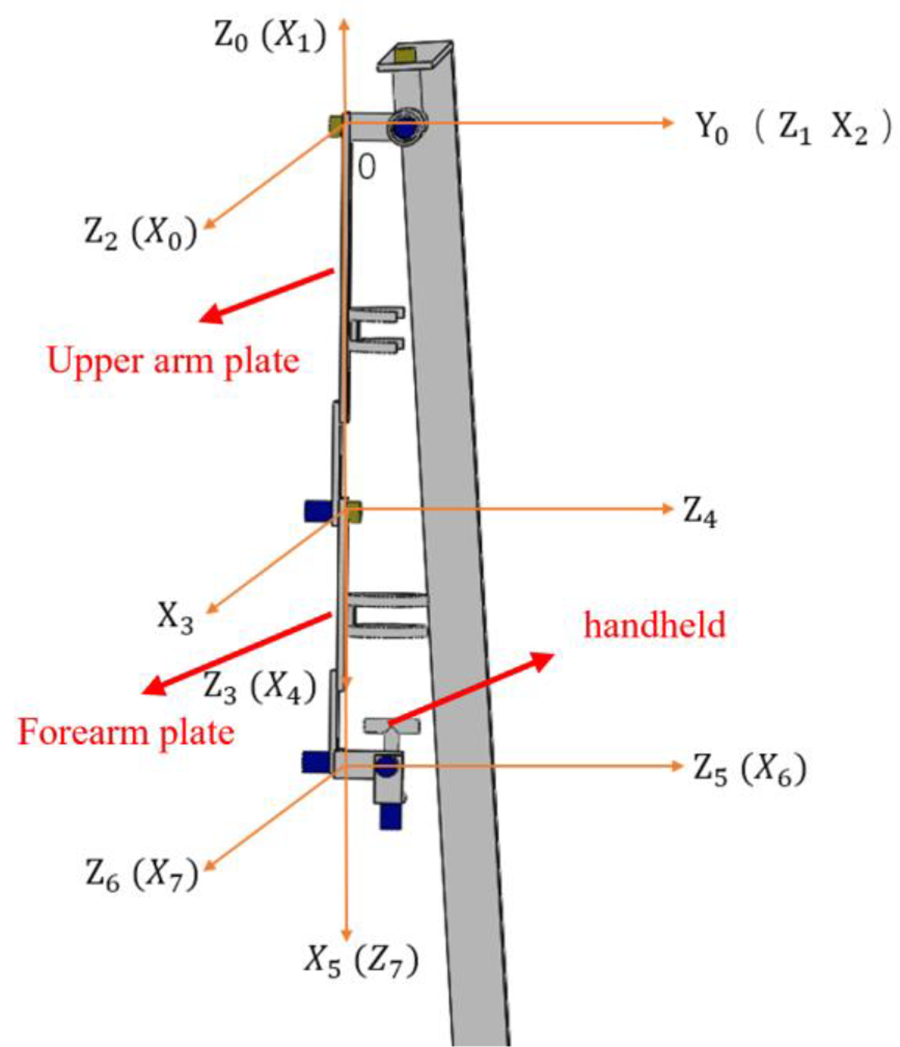


where Pm
is the position of the center of gravity of the exoskeleton manipulator;
Using the D-H method to analyze the forward kinematics of the manipulator
The homogeneous transformation matrix
where c is cos and s is sin,
From Figure 1 and Table 1, we can see the rod length and joint angle of the exoskeleton rehabilitation manipulator, from which we get the D-H parameters as shown in Table 3.
D-H parameter table.
In order to establish the forward kinematic model of the manipulator, suppose the end attitude matrix of the manipulator is


where the values of
Inverse kinematic analysis
The inverse solution of the manipulator is based on knowing the end pose of the manipulator and solving the motion angle of each joint. For a manipulator with redundant DOFs, its inverse solution will be more complicated. Therefore, this article uses the minimum energy standard to solve the inverse kinematics with 7 DOFs. The most important parameter used is the self-motion angle
Calculation standard of total energy consumed
The main difficulty of the inverse solution is to solve the total energy consumed formula. The difficulty of this formula is to solve the changing height of the gravitational potential energy and the elastic potential energy stored in the human arm. Assuming that the total energy consumed by the humanoid rehabilitation manipulator in the movement process is W, it is converted into the gravitational potential energy of the manipulator and the human arm and the elastic potential energy stored in the human arm without considering the energy loss. Therefore, the formula for calculating the total energy consumption W is as follows

where mu
, mf
, and mh
are the total mass of the rehabilitation manipulator and the patient’s upper arm, the total mass of the forearm, and the total mass of the hand. g is the acceleration due to gravity;

Solving inverse kinematics based on the theory of elbow self-motion
As shown in Figure 3, the self-movement of the elbow assumes that the shoulder and wrist joints are fixed, and the elbow can also move along an ellipse. We assume that the imaginary motion trajectory around the ellipse is L.

Schematic diagram of elbow self-movement.
First, solve the W position: given the end pose coordinate system
Split the known homogeneous transformation matrix of the end pose into a rotation matrix and a translation matrix, formulas are as follows

To find the position W,

where,

As shown in Figure 4, knowing that the space base coordinate systems. So, we assume that the imaginary axis of


in the above formula,


The relationship between the two coordinate systems.
A new coordinate

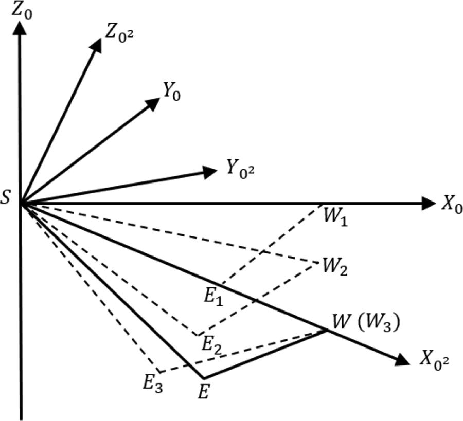
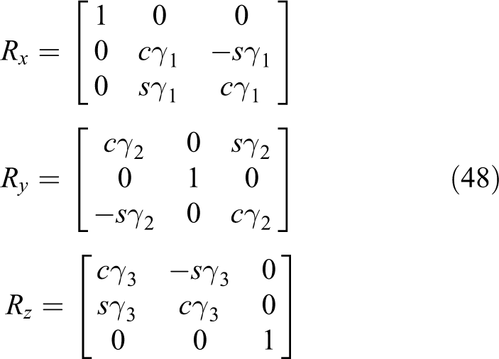
Schematic diagram of the rotation of point W in space.
As shown in Figure 6,


where

The position of point E under the coordinate system


New coordinate system.
It is assumed that the initial pose of the end is in the negative direction of the axis


Then u and f are transformed into the space base coordinate system 0 as follows


The increased height of the three arms can be obtained


The minimum energy consumption standard to solve ϕ
From the above derivation, the total energy that needs to be consumed during the movement of the rehabilitation manipulator can be obtained as

Since the total energy W is a quadratic function concerning the angle of self-movement, the total energy W is derivable and has a minimum value at the zero points after the derivation. Let

From the above formula, can be seen that for solving angle
Calculate the rotation angle of each joint
First, calculate the angle of the first 3 DOFs, so, need to know


The formula can be obtained


where the values of a 1 to a 4 are in Appendix 2.
For solving


Self-motion in two situations.
Therefore, the formula for solving angle

Because

The calculation results are as follows

where ci
is
The


where the values of a 5 to a 9 are in Appendix 3.
Therefore, the angles of all DOFs have been calculated.
Forward and inverse kinematic simulation analysis
This section mainly simulates and analyzes forward and reverse movement. The forward kinematic part mainly uses the joint space trajectory function (jtraij) to verify the established D-H matrix and then analyzes the end pose workspace of the 7-DOF human-like rehabilitation manipulator. The inverse kinematic part uses the method proposed in the previous section to perform calculations and then perform theoretical analysis.
Forward simulation analysis
To control the joint motion of the rehabilitation manipulator model established above, we use the jtraij in formula (43) to simulate the joint motion of the manipulator. The jtraij represents the change trajectory of joint coordinates from the initial joint angle to the end joint angle

where p 1 and p 2 represent the initial and final positions of the joint movement, and time changes from 0 to 1 in M steps.
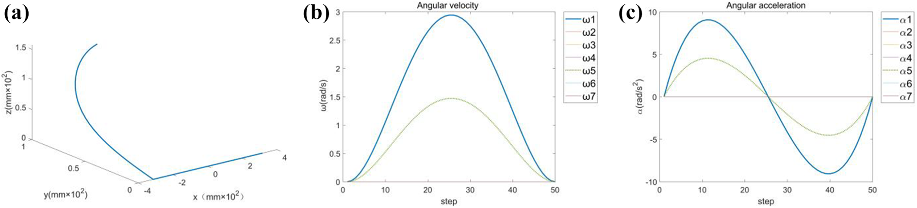
To verify that the manipulator can have a better effect in rehabilitation training, we simulated three sets of training methods. The first group is shoulder adduction and abduction and wrist adduction and abduction,

Shoulder adduction/abduction and wrist adduction/abduction. (a) End trajectory of the manipulator. (b) Angular velocity. (c) Angular acceleration.
Shoulder internal/external rotation and elbow flexion/extension. (a) End trajectory of the manipulator. (b) Angular velocity. (c) Angular acceleration.
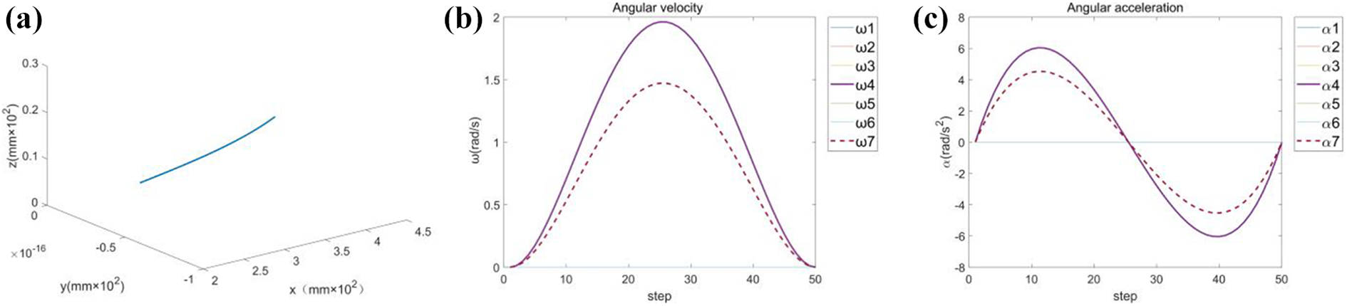
Elbow flexion/extension and wrist internal/external rotation. (a) End trajectory of the manipulator. (b) Angular velocity. (c) Angular acceleration.
Manipulator end pose working space
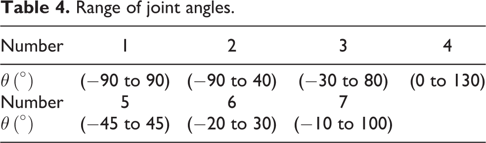
According to the range of motion of the human arm joint angle, analyzed the end working space of the rehabilitation manipulator. The range of each angle is shown in Table 4.
Range of joint angles.
In this article, the Monte Carlo method is used to solve the end pose workspace of the 7-DOF manipulator. The Monte Carlo method is a numerical method for solving mathematical problems by random sampling. The Monte Carlo method can be used to solve the workspace of the articulated manipulator. The workspace solved by this method can display the workspace conveniently by using the computer’s graphic display function. The Monte Carlo method does not require the rotation range of each axis, and the error of the space point cloud is also independent of dimension.
The mathematical principle of this method is as follows: using random functions

where
We use the Monte Carlo method to randomly select 30,000 sets of points θ 1–θ 7 and calculate the vector coordinates X, Y, and Z of the end posture of the 7-DOF manipulator. Draw the working space that the manipulator can reach, as shown in Figure 11(a). To show the working space of the 7-DOF robot more clearly, the cross-sectional observation and analysis diagrams of the XOY, XOZ, and YOZ planes of the working space are obtained, as shown in Figure 11(b) to (d).

End pose workspace of the manipulator. (a) Three-dimensional workspace. (b) XOY plane workspace. (c) XOZ plane workspace. (d) YOZ plane workspace.
Without considering the influence of the mechanical mechanism on the working space, the theoretical space of the 7-DOF rehabilitation manipulator is obtained through simulation. It can be seen from Figure 11 that the working space of the manipulator is also affected by the DOF of the joints. It can be seen from the plane projection that the working space of the manipulator conforms to the rotation range of each joint, and the simulation result conforms to the actual space of the manipulator.
Simulation analysis of inverse kinematic solution
Assuming that the end pose of the manipulator is known, suppose the Euler angle of

The rotation matrix of the Euler angle to represent the desired pose of the end is

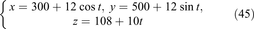
In this article, the time is (0–8π) seconds. As shown in Figure 12(a) is the end pose’s desired trajectory, which is a spiral in space, and (b) is the Euler angle change diagram of the terminal pose.

Given known conditions. (a) Desired trajectory of the end effector. (b) Euler angle of end pose.
We use the end posture of the 7-DOF human-like rehabilitation manipulator to obtain the angle change of each joint using the minimum energy standard method established in this article. The time limit is set to (0–8π), and the distance between points is
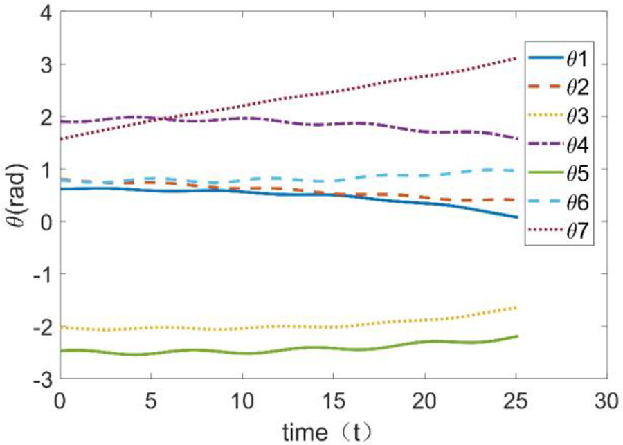
Changes in joint angle.
It can be seen from Figure 13 that within the specified trajectory and time, the minimum energy standard method can obtain the change of the joint angle, and the change is a smooth curve. It can be seen from Figure 14 that the angle value

Self-motion angle (
We have solved the initial angle and end angle of each joint through the inverse solution method. To verify the above inverse solution method, we use the Cartesian space trajectory function (ctraj) of formula (49) to do straight-line trajectory planning. The ctraj represents the Cartesian trajectory from the attitude P 1 to P 2, and there are step points of trapezoidal velocity distribution along the path

where P 1 is the calculated starting position of the joint angle, and P 2 is the calculated ending position of the joint. N is the number of trapezoidal velocity distribution points along the path.

The result of the inverse solution. (a) Straight track
We use the minimum energy standard method to obtain the joint angle as the input of the inverse solution, and obtain the linear trajectory, joint angle, angular velocity, and angular acceleration of the inverse solution, as shown in Figure 15(a) to (d). The inverse solution method in this article is the same as the linear interpolation method. By comparing the results, it is found that there is a certain error between the obtained linear interpolation trajectory and the set trajectory, which shows that the inverse solution method has certain limitations.
Conclusion and prospect
This article refers to the distribution of the length of the human arm and the joint angle to theoretically analyze the kinematics of the 7-DOF rehabilitation manipulator. The forward kinematics of the tandem manipulator is relatively simple, while the inverse solution of the tandem redundant DOF manipulator is more difficult. This article is based on the minimum energy criterion to solve the inverse of the 7-DOF redundant manipulator. The minimum energy standard is used to solve the self-movement angle of the elbow. In the solution, an auxiliary parameter is also introduced to analyze the self-motion manifold of the elbow and solve
This article uses Matlab® robotic toolbox to verify the forward kinematics and inverse kinematics of the manipulator. The result shows that the forward kinematic analysis is correct. We use the inverse kinematic analysis method to calculate the angle of each joint and use the ctraj function to verify the method. The results show that there is a certain error in the method of using the minimum energy standard. In addition, there are some points worth exploring in future research. Questions: (1) Because this method first solves the self-motion angle, but when the weight of the upper arm and forearm changes (the ratio remains the same), the angle of each joint changes differently, and no rule is found; (2) when the motion time changes for a long time, the joint angle calculated by the method in this article will be singular, and the reason for the singularity and the avoiding method has not been found. (3) The obstacle avoidance research of the manipulator is also very important. The next research can consider obstacle avoidance.
Footnotes
Declaration of conflicting interests
The author(s) declared no potential conflicts of interest with respect to the research, authorship, and/or publication of this article.
Funding
The author(s) received no financial support for the research, authorship, and/or publication of this article: This research was funded in part by the National Natural Science Foundation of China under Grant 82004259, in part by the GuangDong Basic and Applied Basic Research Foundation under Grant 2020A1515110503, in part by the Guangzhou Basic and Applied Basic Research Project under Grant 202102020674, in part by the Young Talent Training Project of Guangzhou University of Chinese Medicine under Grant QNYC20190110, in part by the Youth Creative Talent Project (Natural Science) of Guangdong under Grant 2019KQNCX018, in part by the Shanghai Sailing Program 19YF1418900.